ABB ANSI Quick start guide

IEC 61850
—
TECHNICAL GUIDE
ANSI medium voltage metal-clad
digital switchgear
Commissioning and testing guide


—
Table of contents
04 Warranty and general
information
05 Introduction
06 ANSI medium voltage metal-clad
digital switchgear
07– 08 Ethernet network verification
09– 14 Managed Ethernet switches
15 – 17 Interconnections
18 – 24 Primary testing-current sensors
25 – 28 Primary testing-voltage sensors
29 – 33 Apparatus control testing
34 Secondary testing of protection
relays
35– 41 FT-14D Flexitest switch
42– 45 Recommended troubleshooting
tools
46 Glossary

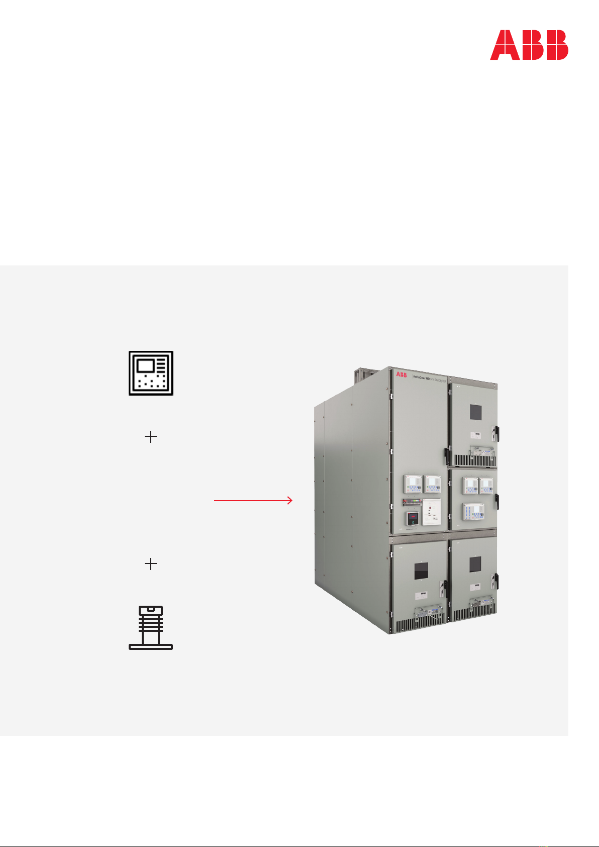
4ANSI MEDIUM VOLTAGE METAL-CLAD DIGITAL SWITCHGEAR
—
Warranty and general information
Read the following hazard classifications
carefully, and fully inspect the equipment for any
identifiable hazards prior to installation,
operation or maintenance. The following
classifications listed below will appear
throughout this document or on labels located on
the equipment. These are standard symbols
defined by ANSI Z535.4-2011 which were
established for recognition of potential hazards
which pose risk to life and property. The
classification is based on the probability and
severity of injury if the hazard is not avoided.
Please follow instructions, warnings, labels and
codes for proper installation, operation, and
maintenance of equipment and devices. Only
Qualified Persons, as defined by NFPA 70, should
provide installation, operation, and maintenance
on this equipment and devices.
Danger symbol/Warning symbol
The addition of either symbol to a "Danger" or
"Warning" safety label indicates that an electrical
hazard exists that will result in personal injury if
the instructions are not followed.
This is the safety alert symbol. It is used to alert
you to potential physical injury hazards. Obey all
safety messages that follow this symbol to avoid
possible injury or death.
Danger: Indicates a hazardous situation which, if
not avoided, will result in death or serious injury.
Warning: Indicates a hazardous situation which, if
not avoided, could result in death or serious
injury.
Caution: Indicates that if the hazard is not
avoided, could result in minor or moderate injury.
Notice: Is used to notify of practices not related
to personal injury.
Trademarks
All rights to copyrights, registered trademarks
and trademarks reside with their respective
owners.
Warranty
This document is based on information available
at the time of publication. While efforts have
been made to ensure accuracy, the information
contained herein does not cover all details or
variations in hardware or software, nor does it
provide for every possible contingency in
connection with installation, operation, and
maintenance. Features may be described herein
that are not present in all hardware and software
systems.
ABB assumes no obligation of notice to holders of
this document with respect to changes
subsequently made. ABB makes no
representation or warranty, expressed, implied,
or statutory, with respect to, and assumes no
responsibility for the accuracy, completeness,
sufficiency, usefulness of the information
contained herein.
No warranties of merchantability or fitness for
purpose shall apply.
WARNING
NOTICE
CAUTION
DANGER
WARNING
CAUTION
NOTICE
SAFETY
INSTRUCTIONS
DANGER
WARNING
CAUTION
NOTICE
SAFETY
INSTRUCTIONS

COMMISSIONING AND TESTING GUIDE 5
—
Introduction
General information
The commissioning and testing guide provides
information about commissioning and test
activities on the ANSI MV metal-clad digital
switchgear solutions by providing details about
their main components and proven testing
methods. This guide is intended to be a
supplement to the Installation, Operation and
Maintenance Manual (IOMM) for the specific
product lines: Advance MV SG, Advance 27 MV SG,
SafeGear MV SG, SafeGear HD MV SG and
ReliaGear ND MV SG.
This guide does not cover the testing and
commissioning of the SwitchgearMD switchgear
monitoring solution. SwitchgearMD is used to
monitor bus temperature, humidity and partial
discharge activity within the switchgear.
This guide also provides basic guidance on
setting up ABB relays and Moxa ethernet switches
and equivalent switches, as well as testing
current and voltage sensors. It is not intended to
replace or supersede the detailed instructions
provided for those, or any other components
used within the switchgear. Users should consult
with the specific User’s Manuals and/or
Installation Manuals for the respective
components used in their switchgear project for
all details regarding testing and commissioning.
Photos of relay screens used in this guide may
differ from actual relays used. These variations
should not be significant enough to invalidate the
intent of the illustrations.
Testing and measurement devices shown in this
guide are not the only devices that can be used.
Performance criteria of the testing and
measuring devices are included so users can
choose alternative devices if desired.
Intended users
This guide is intended to be used by protection
relay, test and service engineers. The protection
relay engineer needs to have a thorough
knowledge of protection systems, protection
equipment, protection functions, configured
functional logic in the protection relays and IEC
61850 engineering. The test and service
engineers are expected to be familiar with the
use of electronic equipment and testing medium
voltage switchgear.

6ANSI MEDIUM VOLTAGE METAL-CLAD DIGITAL SWITCHGEAR
—
ANSI medium voltage metal-clad
digital switchgear
ANSI medium voltage (MV) metal-clad digital
switchgear is a new solution implemented in a
traditional ANSI MV metal-clad switchgear. It is
accomplished by using proven components such
as current and voltage sensors and Relion®
protection relays and mature technologies such
as IEC 61850 digital communication.
Commissioning is very similar to commissioning
activities performed on traditional switchgear.
Differences in procedures are a result of the
implementation of Process bus and GOOSE
functionalities and usage of sensors.
The traditional method of commissioning activity
starts with primary injections, then continues
with protection relays testing, apparatus
functionality verification, etc., and ends with
testing of the communication if applicable. With
digital switchgear, commissioning must start
with verification of IEC 61850 digital
communication, particularly with the Ethernet
network check. After commissioning of the
Ethernet network, there is no restriction
regarding the order of other commissioning
activities.
—
01 ReliaGear ND MV
SG Digital and its
key components
—
01

COMMISSIONING AND TESTING GUIDE 7
—
Ethernet network verification
The Ethernet network interconnects protection
relays in a substation. As the GOOSE and Process
bus are used, having a functional network is
essential for most of the tests. The network may
or may not be set up and tested in the factory,
depending upon purchase contract agreements.
Therefore, after switchgear is assembled onsite,
it may be necessary to set up the network and
then verify its functionality. Before starting any
testing of the communication, properly set the
Ethernet settings in the protection relays, set the
Ethernet switches and, only then, interconnect
the Ethernet network according to the project
documentation. It is assumed that the protection
and control circuits are powered from either the
power supply identified in the project schematic
diagrams, or an alternate power supply if the
switchgear is not energized.
Protection relays
Before starting any secondary testing of the
protection relay functions, verify if the IP
addresses, the network topology and time
synchronization settings are in accordance with
the project documentation.
• IP address setting: Check communication
board setting according to documentation (for
example, the Network Overview diagram).
On the protection relay LHMI go to -> Main Menu/
Configuration/Communication/Ethernet/Rear
port(s)
• IP address = for example, 172.16.2.1
• Subnet mask = for example, 255.255.0.0
• Network topology setting: Check the network
topology setting according to the
documentation.
—
02 IP address setting
for rear port(s)
—
03 Network topology
setting and its
Redundancy mode
—
02
—
03
On the protection relay LHMI go to -> Main
Menu/Configuration/Communication/
Ethernet/Redundancy/Redundant mode
• Redundancy mode = None
• Redundancy mode = HSR (High-availability
Seamless Redundancy protocol)
• Redundancy mode = PRP (Parallel Redundancy
Protocol)
• Time synchronization setting:
Check the setting of time synchronization. For
Process bus functionality, the IEEE 1588 proto-
col must be set up.
On the protection relay LHMI go to -> Main
Menu/Configuration/Time/Synchronization/
Synch source
• Synch source = IEEE 1588
Protection relays, Ethernet switches and Time
Synchronization Clocks must be in the same
PTP domain ID (PTP = precision time protocol).
On the protection relay LHMI go to -> Main
Menu/Configuration/Time/Synchronization/
PTP domain ID
• PTP domain ID = 0

8ANSI MEDIUM VOLTAGE METAL-CLAD DIGITAL SWITCHGEAR
Voltage sender protection relays
On the protection relay LHMI go to -> Main
Menu/Configuration/Time/Synchronisation
• PTP priority 1 = 127
• PTP priority 2 = 128-255 to be different in each
protection relay
Check time synchronization status at the voltage
sender protection relay.
On the protection relay LHMI go to -> Main Menu/
Monitoring/IED status/Time synchronization
• Synch source = IEEE 1588 master
In case of Grandmaster clock (Satellite
controlled clock) failure, it is necessary to have
one protection relay defined as the Master
clock and one protection relay as the Backup
master clock. It is a matter of PTP priority
setting. Devices with a lower PTP priority 2
value become the first master clock.
Check the time synchronization status at other
protection relays.
On the protection relay LHMI go to -> Main Menu/
Monitoring/IED status/Time synchronization
• Synch source = IEEE 1588 slave
Notice: If both, Master and Backup
master clocks fails, the protection
relays establish a new primary
source for time synchronization
information automatically.
—
04
—
05
—
06
—
07
—
04 PTP priority setting
for Master clock
—
05 PTP priority setting
for Slave clock
—
06 IEEE 1588 master
clock status
—
07 IEEE 1588 slave
clock status
Other protection relays
On the protection relay LHMI go to -> Main Menu/
Configuration/Time/Synchronization
• PTP priority 1 = 128
• PTP priority 2 = 128
NOTICE

COMMISSIONING AND TESTING GUIDE 9
—
08 MX Config – location
of globe icon
—
09 Broadcast
Search Filters
—
Managed Ethernet switches
To create a reliable Ethernet network for IEC
61850 communication, a managed Ethernet
switch (e.g., from Moxa) is recommended to be
used. The most important settings of Moxa EDS
family Ethernet switches to be observed are
highlighted in this section.
This section provides the basic information on
how to make the initial setup of a typical Moxa
switch. User must refer to the correct User’s
Manual and/or Instruction Manual for the Moxa
switch for details of how to completely setup
and/or program the Moxa ethernet switches. The
instructions within the Moxa User’s Manual and/
or Installation Manuals take precedence over all
instructions within this guide.
Moxa EDS switches
If the IP address is unknown, disconnect all
Ethernet cables from the switch or turn other
connected Ethernet switches off. After
connecting a computer with the Moxa MXConfig
tool installed to any port on the Ethernet switch,
the following dialog screen appears (Figure 8).
This tool automatically searches the network for
those devices, which support the tool.
Click on the globe icon to open broadcast search
(Figure 8).
—
08
—
09
From the Broadcast Search screen select the
ethernet switch and click on “Search”. (Figure 9)
This will take you to the properties dialog screen
for the selected ethernet switch (Figure 10)
—
10

10 ANSI MEDIUM VOLTAGE METAL-CLAD DIGITAL SWITCHGEAR
Selection of the crystal ball will take you to the
web page sign on page of the switch. Refer to the
appropriate User’s Manual or Instruction Manual
for the selected Moxa switch to obtain the default
login name and password and enter it here.
(Figure 12)
—
10 Search results
showing the discovered
switch by MXconfig
—
11 Location of
crystal ball
—
12 Moxa login screen
Once the switch is found and displayed in the
properties dialog screen, click on the crystal ball.
(Figure 11)
—
11
—
12
The user-friendly web-based interface of Moxa
switches offers the possibility of operating the
device from any location in the network via a
standard browser such as Mozilla Firefox or
Microsoft Internet Explorer. Being a universal
access tool, the web browser uses an applet
which communicates with the device via the
Simple Network Management Protocol (SNMP).

COMMISSIONING AND TESTING GUIDE 11
Once the IP settings are entered, the default
passwords can be changed if the user desires.
Select “Password” under the Basic Settings
—
13
—
14
—
13 IP Settings
information screen
—
14 Password
setting screen
After entering the correct account and password
information, enter the IP settings under the IP
Selection menu. (Figure 13).
section of the Main Menu on the left of the
screen. This will open the password setting
dialog box. (Figure 14)

12 ANSI MEDIUM VOLTAGE METAL-CLAD DIGITAL SWITCHGEAR
—
15
—
15 Port configuration
dialogue
—
16 PTP Transparent
clock Port dialog
Time settings
It is recommended to set a transparent time with
Power profile. The Ethernet switch then only
corrects and forwards the PTP messages and
cannot become the PTP master.
This concludes the Time Settings activities.
Switching Settings (VLAN)
The traffic segregation is especially essential for
the process bus to reduce data traffic and to let it
go only where needed (for example GOOSE, SMV
shared between protection relays should not be
sent to the control system, SMV should only be
sent where required).
—
16
Traffic filtering in managed Ethernet switches
can be done via logical separation of the data
traffic to several VLANs or via multicast MAC
address filtering for ports.
Select “VLAN Settings” from the menu to open
the VLAN settings dialog box. (Figure 17) Follow
the diagrams as shown in Figures 18 and 19.
The PTP profile must be enabled on all ports. The
Peer to peer delay interval is definite for power
profile 1s.
Set the time values under the PTP settings as
shown in Figure 16.

COMMISSIONING AND TESTING GUIDE 13
—
17
—
18
—
17 Switching VLAN
Global dialog
—
18 Switching
Global dialog
—
19 Switching
Global dialog
—
19

14 ANSI MEDIUM VOLTAGE METAL-CLAD DIGITAL SWITCHGEAR
This concludes the Switching Settings (VLAN)
activities.
PRP and HSR redundancy settings
This section is only valid if PRP and HSR are
required for the application. This should be
defined in the project scope for the switchgear at
the time of ordering. For PRP HSR applications
use the MOXA PT-G503 switches instead of their
switches as shown in Basic Settings on page 11.
PRP
There is no special setting in the Ethernet switch
for PRP networks.
This concludes the basic setup of the Moxa
ethernet switch. Consult the User’s Manual and/
or Instruction Manual for the appropriate switch
provided in the switchgear for complete and
detailed instructions on how to set up, program,
operate and maintain Moxa switches.
—
20
—
20 Redundancy protocol
network settings HSR
Check the HSR parameters setting according to
the Moxa User’s Manual or Instruction Manual. It
varies based on the network topology used.
Select “Redundancy Protocol” under the Home
menu to access HSR screen. HSR can be
configured from this screen as required by the
project needs. Consult the appropriate User’s
Manual and/or Instruction Manual for updating
this screen.

COMMISSIONING AND TESTING GUIDE 15
—
Interconnections
Check the interconnection of network
components (protection relays, managed
Ethernet switches) according to drawings
provided in the project documentation (for
example, the Communication Diagram and Wiring
Diagrams).
—
21 Example of
Communication diagram
PE
PG
PI
PJ
CMB
PE
Port 1 Port 1
Port 1
Port 1 Port 1
Port 1 Port 1
Port 1
Port 1 Port 1
Port 1 Port 1
Port 1
Port 1
Port 1 Port 1
Cubicle 01
Cubicle 05
CNB
P10P16
P23P22
P13P3
P19P14
P10P15
P4P24
P12P6
P21P20
P6P2
P11P7
P17P9
P5P1
Cubicle 02Cubicle 03Cubicle 04
PE
PE
PE
PE
PE
PE
PE
PG
PG
PG
PG
PG
PG
Cubicle 10 Cubicle 07Cubicle 09Cubicle 08Cubicle 06
—
21
Ethernet switch
Relays

16 ANSI MEDIUM VOLTAGE METAL-CLAD DIGITAL SWITCHGEAR
Protection relay
Check the connection status of protection relays
via PCM600. Open the project provided by the
Engineering function responsible for
programming the relays and select the protection
relay for which you want to check the connection.
—
22
—
23
—
22 Example of
Interconnection
Wiring Diagram
—
23 Example of Plant
Structure in PCM600
If the connection between the PCM600 and
protection relay is established, a green tick mark
is shown next to the protection relay icon. (Note:
If no programing record is available, then contact
the Engineering function responsible for
programming the relays to obtain this file.)

COMMISSIONING AND TESTING GUIDE 17
Network redundancy
Check the availability of voltage measurements
and GOOSE signals when the managed Ethernet
switch, communication link or protection relay
fails.
GOOSE and Process bus
The GOOSE / SMV alarm is assigned to a
configurable LED via the PCM600 and it relates to
function blocks (GSELPRT1 – GOOSE supervision
and ULTVTR1 – SMV supervision).
—
24
—
25
—
26
—
24 GOOSE / SMV
alarm is activated on
a configurable LED
—
25 Measurements
view, voltage receiver
protection relay is not
synchronized with
the Master clock
—
26 Measurements
view, voltage receiver
protection relay is
synchronized with
the Master clock
Check the Measurements view on
the voltage receiver protection
relays if voltage values are not in
brackets.
Notice: Brackets indicate an invalid
or a questionable measurement
due to, for example, a time
synchronization error.
Notice: Frequency information in
the Measurements view is in
brackets if no voltage is measured
by the protection relay.
NOTICE
NOTICE
Check if No GOOSE / SMV alarm is reported by
the receiver protection relays.

18 ANSI MEDIUM VOLTAGE METAL-CLAD DIGITAL SWITCHGEAR
All current and voltage sensors can remain
connected to the bus during power frequency
(bus hipot) and secondary wire dielectric testing.
Primary testing is valuable for verification of the
whole measurement chain in the application
including switching equipment (circuit breaker or
contactor). The measuring chain includes the
sensor, cable connections and settings of the
protection relay.
Digital solution vs. traditional switchgear
The following applies in the case of digital
switchgear:
• No complex checks of inter-panel wiring are
required
• Ethernet network fault detection is available
• Higher protection relay engineering skills are
required in case of modifications
• Relay configuration modifications can be
performed using the free downloadable
PCM600 software
• For pre-testing, secondary tester with sensor
support (low voltage output signals) is required
• The setting of sensors in the protection relay is
described in the Digital Switchgear Engineering
guide 1VAL108402-TG Rev A
Recommended primary testing device
For primary current and voltage injection you can
use the same devices as with conventional
switchgear. There are multifunctional primary
test systems, such as the Omicron CPC 100
(Figure 27), available on the market which enables
entering sensor correction factors and the
display of the corrected value for both current
and voltage sensors.
Introduction of CPC 100 – key features:
• Supply up to 800 A or 2000 V with max. 5 kVA
power output, over a frequency range of 15 Hz –
400 Hz or 400 A DC
• Supply up to 2000 A or 12 kV using external
current or voltage amplifiers
Current sensors
Primary testing verifies the whole measurement
chain including the sensor, cable connections and
settings of the protection relay. Each current
sensor has unique physical polarity. Therefore, no
polarity (physical test) is needed. The current
sensor polarity can be changed via the relay
parameter setting. Secondary winding resistance
and magnetization curve tests are not applicable
either.
All current sensors are tested individually during
routine production tests for output accuracy and
determination of the ratio correction factors.
Production test reports are available for all
sensors and are provided when requested. It is
not required to test the sensors separately from
the entire chain.
If it is desired to test only the sensors, separate
from the entire circuit, then follow only the steps
shown below that are necessary to establish a
primary current injection circuit and then connect
a measurement device to the RJ45 connectors of
the sensor outputs. Please note that the
measurement and power supply devices are
suggested devices. Performance characteristics
are stated in case the user wants to use alternate
power supply and measuring devices.
The measurement device should have a
measurement range of 5 mV to 20 V, with an
accuracy of +/-0.1% or better.
—
27
—
27 Primary test system
CPC 100 from Omicron
—
Primary testing-current sensors

COMMISSIONING AND TESTING GUIDE 19
All current sensors are factory tested for accuracy
in the continues primary current operating range,
i.e., from 5% of rated primary current (4 A) up to
the continues thermal current Icth (4000 A).
These routine tests are made as per the
requirements of the sensor standards IEC
60044-8 or IEC 61869-10.
The test value is 80 A which represents a rated
primary current. Other primary current input
values can be used. However, since sensors are
linear in performance then it is not necessary to
test all primary inputs. If the 80 A primary test
results are within range, then the outputs for the
other primary inputs will be in range.
The chart below shows what the output voltage
should be based on the primary current used.
The acceptable output range is +/- 5.0 % of the
target value shown on the chart.
Multiply the ratio correction factor (ref. Step 1/5
below). This calculated value based on the
correction factors should be within +/- 0.5% of
the secondary output values shown in the table.
—
Primary Current
Input Amps
Secondary
Output (mV)²
1. Primary injection test equipment assumed to have a +/-0.1%
accuracy or better
2. Output voltage without the use of correction factors to be +/- 5.0%
of secondary output value shown on table above. (e.g., for 80 A
primary, output voltage can be 171 mV to 189 mV). After multiplying
the correction factors to the actual output voltages, the output
voltages should be +/- 0.5% of the values shown in the table. (e.g.,
for 80 A primary, output voltage can be 179.1 to 180.9 mV).
Consideration shall also be given to the accuracy range of the
primary current injection equipment.
3. All values are based on 60Hz.
The test setup to measure the secondary output
of the sensors is shown in Figure 29. ESSAILEC
test socket pt#TC-E-RJ45-INF and RJ45 plug,
pt#FI-RJ45-DIA4 are used to in the illustration
below. These are specifically designed to be used
with ABB digital switchgear with sensors
compliant to the IEC standards.
There may be other similar devices available that
could be used. Measuring device can be any
device capable of measuring the recommended
ranges and comply with the proper IEC standard
input parameters for accurate measuring.
RJ45 connectors have specific pin wiring based
on the requirements of the IEC standards for the
sensors. Test personnel must ensure that any
adapters or connections using RJ45 connectors
meet these requirements.
Extensions of the CAT6 cable can be made up to
about 1 meter in length and must follow the same
pin wiring as the sensor cable.
Supervision
In the protection relay, current metering is
supervised by the CMMXU function. Metering
accuracy is stated in Table 2.
—
Characteristic Value
Operation
accuracy
Depending on the frequency of the
A measured value under the zero-point clamping
limit is forced to zero. This allows the noise in the
input signal to be ignored. Read more details in
the technical manual of the protection relay.

20 ANSI MEDIUM VOLTAGE METAL-CLAD DIGITAL SWITCHGEAR
DANGER
WARNING
CAUTION
NOTICE
SAFETY
INSTRUCTIONS
—
Function
Three-phase current
measurement (CMMXU)
Residual current
measurement (RESCMMXU)
Phase sequence current
meas. (CSMSQI)
Main bus and breakers installed in the
switchgear frame
This testing procedure includes the influence of
applications such as the circuit breaker or
contactor. Installed busbars are used to make the
electrical circuit between two neighboring
frames.
Danger: If high voltage cables are terminated to
switchgear frame, ensure the installation is dead.
Protect against any other live parts.
• Step 1/5
Verify sensor parameters set in the protection
relay with sensor rating plates found on the
sensors. These may be found on the circuit
breaker compartment door or in the low voltage
wiring compartment.
—
28
—
28 Example of a
current sensor label
—
29 Current sensor
parameters
On protection relay LHMI go to -> Main Menu/
Configuration/Analog inputs/Current (3I, CT)
• Primary current = Application nominal current
• Amplitude Corr A = sensor rating plate, phase A
• Amplitude Corr B = sensor rating plate, phase B
• Amplitude Corr C = sensor rating plate, phase C
• Nominal current = Primary current
• Rated secondary Val = Rated secondary value in
mV/Hz
• Angle Corr A = sensor rating plate, phase A
• Angle Corr B = sensor rating plate, phase B
• Angle Corr C = sensor rating plate, phase C
• Step 2/5
Move two neighboring circuit breakers into the
connected position and close them.
Notice: Default values of
overcurrent, earth fault and
unbalance protection functions
can operate the circuit breaker
during primary injection. Disable
all related protection functions in
the protection relay or disconnect
the tripping coil (MO) from the
negative potential of power supply
in the low voltage compartment
before primary injection to avoid
unwanted tripping of the circuit
breaker.
—
29
NOTICE
Table of contents
Other ABB Industrial Equipment manuals

ABB
ABB HT600369 User manual

ABB
ABB HT575445 User manual

ABB
ABB HT572399 User manual

ABB
ABB HT566060 User manual

ABB
ABB HT593478 User manual

ABB
ABB HT569272 User manual

ABB
ABB HT578272 User manual

ABB
ABB RELION 650 SERIES Installation and operation manual

ABB
ABB Tmax PR232 User manual

ABB
ABB HT596239 User manual