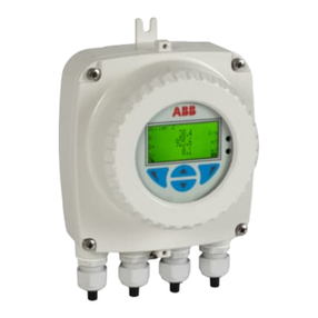
ABB ProcessMaster FEP630 series User manual

—
ABB MEASUREMENT & ANALYTICS | INTERFACE DESCRIPTION | COM/FEP630/FEH630/E/MB-EN REV. A
ProcessMaster FEP630, HygienicMaster FEH630
Electromagnetic flowmeter
EtherNet/IP, Modbus TCP, Webserver
Valid from firmware version 01.09.00
Measurement made easy
Introduction
This manual describes how to configure an Ethernet
connection for the following electromagnetic
flowmeters:
• ProcessMaster FEP630
• HygienicMaster FEH630
For more information
Additional documentation on ProcessMaster,
HygienicMaster FEX600 series is available for
download free of charge at www.abb.com/flow.
Alternatively, simply scan this code:
—
ProcessMaster FEP630,
HygienicMaster FEH630

2PROCESSMASTER FEP630, HYGIENICMASTER FEH630 | COM/FEP630/FEH630/E/MB-EN REV. A
Contents
1 Safety . . . . . . . . . . . . . . . . . . . . . . . . . . . . . . . . . . . . . . 3
General information and instructions . . . . . . . . . . . . . . . . . . . . . . . . 3
Notes on data safety. . . . . . . . . . . . . . . . . . . . . . . . . . . . . . . . . . . 3
2 Supported Ethernet-based communication protocols . . . . . . . . 3
EtherNet/IP defined in IEEE 802.03 . . . . . . . . . . . . . . . . . . . . . . . . . 3
Webserver – Secure http (https) . . . . . . . . . . . . . . . . . . . . . . . . . . . 3
Modbus TCP . . . . . . . . . . . . . . . . . . . . . . . . . . . . . . . . . . . . . . . . 3
3 Security . . . . . . . . . . . . . . . . . . . . . . . . . . . . . . . . . . . . . 3
Secured protocols . . . . . . . . . . . . . . . . . . . . . . . . . . . . . . . . . . . . 3
Unsecured protocols. . . . . . . . . . . . . . . . . . . . . . . . . . . . . . . . . . . 3
4 Connecting Ethernet to the flowmeter . . . . . . . . . . . . . . . . . . 4
Ethernet card – Port function assignment and color-coding . . . . . . . . . . 4
Power over Ethernet (PoE) . . . . . . . . . . . . . . . . . . . . . . . . . . . . . . . 5
Preparing the EtherNet Cat5e cable . . . . . . . . . . . . . . . . . . . . . . . . . 6
How to connect the shielding of the Ethernet cable . . . . . . . . . . . . . . . 6
M12 plug (option) . . . . . . . . . . . . . . . . . . . . . . . . . . . . . . . . . . . . . 6
RJ45 connector (option) . . . . . . . . . . . . . . . . . . . . . . . . . . . . . . . . 7
Wiring with different network topologies . . . . . . . . . . . . . . . . . . . . . 8
Parameterization for start-up . . . . . . . . . . . . . . . . . . . . . . . . . . . . . 9
Ethernet card status LEDs . . . . . . . . . . . . . . . . . . . . . . . . . . . . . . . 10
5 Webserver for device configuration. . . . . . . . . . . . . . . . . . . 11
Flowmeter settings . . . . . . . . . . . . . . . . . . . . . . . . . . . . . . . . . . .11
Computer settings . . . . . . . . . . . . . . . . . . . . . . . . . . . . . . . . . . . . 11
6 Web page access. . . . . . . . . . . . . . . . . . . . . . . . . . . . . . . 11
Password . . . . . . . . . . . . . . . . . . . . . . . . . . . . . . . . . . . . . . . . . . 11
Webpage certificates . . . . . . . . . . . . . . . . . . . . . . . . . . . . . . . . . .12
7 Device to network . . . . . . . . . . . . . . . . . . . . . . . . . . . . . . 13
8 EtherNet/IP. . . . . . . . . . . . . . . . . . . . . . . . . . . . . . . . . . 13
Device profile . . . . . . . . . . . . . . . . . . . . . . . . . . . . . . . . . . . . . . . 13
9 Menu Structure in HMI . . . . . . . . . . . . . . . . . . . . . . . . . . . 14
10 Set the IP-Address and Local Host name. . . . . . . . . . . . . . . . 16
IP address setting . . . . . . . . . . . . . . . . . . . . . . . . . . . . . . . . . . . .16
11 EtherNet/IP interface . . . . . . . . . . . . . . . . . . . . . . . . . . . 17
12 EtherNet/IP interface details . . . . . . . . . . . . . . . . . . . . . . . 22
13 EtherNet/IP unit overview. . . . . . . . . . . . . . . . . . . . . . . . . 29
14 Ethernet card firmware update . . . . . . . . . . . . . . . . . . . . . 30
Cyber Security. . . . . . . . . . . . . . . . . . . . . . . . . . . . . . . . . . . . . . . 31

PROCESSMASTER FEP630, HYGIENICMASTER HEP630 | COM/FEP630/FEH630/E/MB-EN REV. A 3
1 Safety
General information and instructions
These instructions are an important part of the product and
must be retained for future reference.
Installation, commissioning, and maintenance of the product
may only be performed by trained specialist personnel who
have been authorized by the plant operator accordingly. The
specialist personnel must have read and understood the
manual and must comply with its instructions.
For additional information or if specific problems occur that
are not discussed in these instructions, contact the
manufacturer.
The content of these instructions is neither part of nor an
amendment to any previous or existing agreement, promise or
legal relationship.
Modifications and repairs to the product may only be
performed if expressly permitted by these instructions.
Information and symbols on the product must be observed.
These may not be removed and must be fully legible at all times.
The operating company must strictly observe the applicable
national regulations relating to the installation, function
testing, repair and maintenance of electrical products.
Notes on data safety
This product is designed to be connected to and to
communicate information and data via a network interface.
It is the operator’s sole responsibility to provide and
continuously ensure a secure connection between the product
and your network or any other network (as the case may be).
Operator shall establish and maintain any appropriate
measures (such as but not limited to the installation of
firewalls, application of authentication measures, encryption of
data, installation of antivirus programs) to protect the product,
the network, its system and the interface against any kind of
security breaches, unauthorized access, interference, intrusion,
leakage and/or theft of data or information.
ABB Automation Products GmbH and its affiliates are not liable
for damages and/or losses related to such security breaches,
any unauthorized access, interference, intrusion, leakage and/
or theft of data or information.
2 Supported Ethernet-based
communication protocols
EtherNet/IP defined in IEEE 802.03
• Cyclic/implicit communication is supported
• Process variables, diagnostic values and Device Status
Information are accessible
• For device configuration a Webserver or Modbus TCP is
available, providing full access to all parameter.
Webserver – Secure http (https)
Use the Webserver or Modbus TCP to configure all of the device
parameters.
Modbus TCP
The common Modbus registers are accessible through Ethernet
via Modbus TCP Protocol. Access to all Registers allows for
device configuration.
3 Security
Secured protocols
Webserver https:
• Security modes
• Used ports by Webserver: TCP 443
• Security is based on .x509 Certificates
• Protocol could be deactivated via HMI if not needed.
Unsecured protocols
Use the HMI menu to enable or disable the protocols:
• Ethernet/IP – use ports TCP 44818, UDP 2222
• Modbus TCP – use port TCP 502.
4PROCESSMASTER FEP630, HYGIENICMASTER FEH630 | COM/FEP630/FEH630/E/MB-EN REV. A
4 Connecting Ethernet to the flowmeter
Ethernet card – Port function assignment and color-coding
The Flowmeter has two slots for the components that follow:
• Slot A: Ethernet card (part number 3KQZ400037U0100)
• Slot B: Power over Ethernet (PoE) card (part number 3KQZ400039U0100)
Figure 1 Ethernet card
A B
X1
X2
X3
X4
X5
X6
X7
X8
RD+
RD-
TD+
TD-
RD+
RD-
TD+
TD-
Port 1
Port 2
Port/Pin Color code on the Ethernet card plug
Port 1 X1 White/orange
Port 1 X2 Orange
Port 1 X3 White/green
Port 1 X4 Green
Port 2 X5 White/blue
Port 2 X6 Blue
Port 2 X7 White/brown
Port 2 X8 Brown
The color code is in accordance with EIA/TIA 568B.
For the functionality assigned to each pin of the Ethernet card
ports, refer to Figure 1.
The Ethernet card has two connection ports. These ports are
not independent.
The internal switch allows for a daisy-chain or ring topology.
The Ethernet card supports one IP address (IPv4).

PROCESSMASTER FEP630, HYGIENICMASTER HEP630 | COM/FEP630/FEH630/E/MB-EN REV. A 5
Power over Ethernet (PoE)
The PoE card Bsupplies power through the Ethernet
connection, so that an external 24 V DC power supply for the
flowmeter is not required. The PoE card (B) converts the 37 to
57 V supply from the Ethernet cable to 24 V DC. This 24 V DC is
available from terminals V3 and V4 and connects to terminals 1+
and 2+, supplying power to the flowmeter. Each port supports
PoE.
The specification is in accordance with IEEE 802.3at/af. PoE
Class 0.
Dependent on how power is supplied over the Ethernet cable,
there are four possible configurations for connecting to the
ports of the PoE card.
Port/Pin Verion 1 Version 2 Version 3 Version 4
Port 1 X1 RD+ & Pwr+ Spare RD+ Pwr+
Port 1 X2 RD- & Pwr+ Spare RD- Pwr+
Port 1 X3 TD+ & Pwr- Spare TD+ Pwr-
Port 1 X4 TD- & Pwr- Spare TD- Pwr-
Port 2 X5 Spare RD+ & Pwr+ Pwr+ RD+
Port 2 X6 Spare RD- & Pwr+ Pwr+ RD-
Port 2 X7 Spare TD+ & Pwr- Pwr- TD+
Port 2 X8 Spare TD- & Pwr- Pwr- TD-
CAUTION
When using PoE, make sure that the PoE card and the red
and blue wires within the transmitter’s termination area are
in place and connected correctly.
Terminal V3 connects to Terminal 1+ and Terminal V4
connects to terminal 2-.
When using PoE, do not connect any other external supply
power to the transmitter's power supply Terminals 1+, 2-.
Cable in
Cable out
How to operate the Ethernet card port plugs
A
B
1
2
3
4

6PROCESSMASTER FEP630, HYGIENICMASTER FEH630 | COM/FEP630/FEH630/E/MB-EN REV. A
…Connecting Ethernet to the flowmeter
Preparing the EtherNet Cat5e cable
1= 90 mm (3.54 in)
2= 39 mm (1.54 in)
3= 60 mm (2.36 in)
4= Tin 10 mm of the end of the braided shield of the cable
How to connect the shielding of the Ethernet
cable
Connect the outer shield of the Ethernet cable to the screw
terminal A.
M12 plug (option)
Various options for M12 plugs are available from the model
code:
• Flowmeter equipped with 1 x M12 (with 4 wires, connecting to
Port 1)
• Flowmeter equipped with 2 x M12 (with 4 wires each,
connecting to Port 1 &2)
• Flowmeter equipped with 1 x M12 (with 8 wires, connecting to
Port 1 &2)
These options allow for connection to different network
topologies:
Topology 4 wires 4 wires 4 wires 8 wires
1 x M12 (4 wires) 2 x M12 (4 wires) 1 x M12 (8 wires)
Star Y Y Y
Ring or daisy-
chain
N Y N
PoE N N Y
For the internal wiring inside the transmitter and the related
pinout within the M12 Plug, refer to table below:
Wiring inside the transmitter
M12
Connector pin
Color Ethernet card
port/pin
34
21
M12 plug with 4 wires
1Yellow Port 1 X1
2Orange Port 1 X2
3White Port 1 X3
4Blue Port 1 X4
46
5
8
7
3
21
M12 plug with 8 wires
1White Port 1 X1
2Blue Port 1 X2
3Brown Port 1 X3
4Green Port 1 X4
5Pink Port 2 X5
6Yellow Port 2 X6
7Grey Port 2 X7
8Red Port 2 X8
1
2
3
4
A

PROCESSMASTER FEP630, HYGIENICMASTER HEP630 | COM/FEP630/FEH630/E/MB-EN REV. A 7
WARNING
There are limitations of the M12 plug in combination with a
hazardous-area-design flowmeter.
No Ex
Area
ATEX/IEX
Zone 2
Div 2
Ethernet cable directly connected to
Ethernet card terminals
Y Y Y
Ethernet cable connected to M12
plug at transmitter housing
Y Y N
WARNING
When using the M12 Plug in combination with a hazardous-
area-design Flowmeter, a retainer clip must be put in place.
A– Retaining clip
RJ45 connector (option)
Various Options for RJ45 connection are available from the
Modelcode. The RJ45 connector is equipped with a certain
length of Ethernet cable – as per model code.
The flowmeter is shipped with the Ethernet cable fitted to the
terminals inside the transmitter:
• Flowmeter equipped with 1 x RJ45 (with 4 wires, connecting
to Port 1)
• Flowmeter equipped with 2 x RJ45 (with 4 wires each,
connecting to Port 1 and 2)
• Flowmeter equipped with 1 x RJ45 (with 8 wires, connecting
to Port 1 and 2)
These options allow for connection to different network
topologies:
Topology 4 wires 4 wires 4 wires 8 wires
1 x RJ45
(4 wires)
2 x RJ45 (4 wires) 1 x RJ45
(8 wires)
Star Y Y Y
Ring or
daisy-chain
N Y N
PoE N N Y
For the internal wiring inside the transmitter and the related
pinout within the RJ45 connector, refer to table below:
Wiring inside the transmitter
Color Ethernet card
port/pin
RJ45 with 4 wires Yellow Port 1 X1
Orange Port 1 X2
White Port 1 X3
Blue Port 1 X4
RJ45 with 8 wires White/orange Port 1 X1
Orange Port 1 X2
White/green Port 1 X3
Green Port 1 X4
White/blue Port 2 X5
Blue Port 2 X6
White/brown Port 2 X7
Brown Port 2 X8
WARNING
There are limitations of the RJ45 plug in combination with a
hazardous-area-design flowmeter.
No Ex
Area
ATEX/IEX
Zone 2
Div 2
Ethernet cable with RJ45 connector
fitted at transmitter housing
Y Y N
A

8PROCESSMASTER FEP630, HYGIENICMASTER FEH630 | COM/FEP630/FEH630/E/MB-EN REV. A
…Connecting Ethernet to the flowmeter
Wiring with different network topologies
A– Daisy-chain
B– Ring
C– Star
Topology No. Ethernet
cables connected
No. wires in
Ethernet cable
PoE Port Pin Function Cable
Star
1 4 No 1
X1 RD+ yellow
X2 RD- orange
X3 TD+ white
X4 TD- blue
1 8 No
1
X1 RD+ white / orange
X2 RD- orange
X3 TD+ white / green
X4 TD- green
2
X5 Spare 1+ white / blue
X6 Spare 1- blue
X7 Spare 2+ white / brown
X8 Spare 2- brown
1 4 Yes 1
X1
Recommendation:
use cable with 8 wires
X2
X3
X4
1 8 Yes
1
X1 RD+ white / orange
X2 RD- orange
X3 TD+ white / green
X4 TD- green
2
X5 Spare 1+ white / blue
X6 Spare 1- blue
X7 Spare 2+ white / brown
X8 Spare 2- brown
Ring or daisy-chain
2 4*No
1
X1 RD+ yellow
X2 RD- orange
X3 TD+ white
X4 TD- blue
2
X5 RD+ yellow
X6 RD- orange
X7 TD+ white
X8 TD- blue
* If you use 8-wire cables, 4 wires will not be connected.
A B C

PROCESSMASTER FEP630, HYGIENICMASTER HEP630 | COM/FEP630/FEH630/E/MB-EN REV. A 9
Parameterization for start-up
On initial start, do the steps that follow:
1 Make sure that the transmitter is connected to the Ethernet.
2 Log on to the flowmeter and set the parameters:
a Set DHCP Client to enabled.
b Make sure that the flowmeter IP address (host IP address)
is set.
c Set Webserver Access to Full.
d Set EtherNet IP Access to Full.
e Set Display Tag to Bus Address.
Communication
Ethernet
General
Internet layer
DHCP client enabled
Host IP address 192.168.1.122
Subnet mask
Webserver
Access Full
Ethernet IP
Access Full
Display
Language
Contrast
Operator Page 1
Operator Page 2
Autoscroll
Flow Format
Date Format
Display Tag
Bus Address (Ethernet address)

10 PROCESSMASTER FEP630, HYGIENICMASTER FEH630 | COM/FEP630/FEH630/E/MB-EN REV. A
…Installation
Ethernet card status LEDs
The 6 LEDs on the Ethernet card indicate the status of each port and the network.
To enable card status indication in the upper HMI Line, navigate to Display > Display Tag > Ethernet Status.
LED Status HMI display Description
A Port 1 ON Network connection (link up)
OFF No network
B Activity 1 Flashing or ON Traffic
OFF No traffic
C Port 2 ON Network connection (link up)
OFF No network
D Activity 2 Flashing or ON Traffic
OFF No traffic
EModule Status (Mod) Green, ON Mod showing <G> continously Device ready for Operation. Working
properly
Green, flashing (1 Hz) Mod changing between <G> and < > Standby. Device not configured yet
Green/ red, flashing (1Hz) Device performs "Power-On" Test
Red, flashing (1 Hz) Mod changing between <R> and < > Simple Error, which can be fixed
Red, ON Mod showing <R> continously Major Error. Non removable serious
error
OFF Mod showing < > continously No Power
FNetwork Status (Net) Green, ON Net showing <G> continously Connected. Device has at least one
established connection
Green, flashing (1 Hz) Net changing between <G> and < > No Connection. Device did not
establish any connections, but was
assigned an IP address
Green/red, flashing (1 Hz) Device performs "Power-On" Test
Red, ON Net showing <R> continously Dublicated IP address. Device has
detected that the device IP address
is already in use
OFF Mod showing < > continously No supply voltage or IP Address.
Red, flashing (1 Hz) Mod changing between <R> and < > Connection timeout
Note
For card status indication in the upper HMI Line, navigate to Display > Display Tag > Ethernet Status.
B
A
C
D
E F

PROCESSMASTER FEP630, HYGIENICMASTER HEP630 | COM/FEP630/FEH630/E/MB-EN REV. A 11
5 Webserver for device
configuration
The built-in webserver allows for device configuration using a
web browser. You must log in to access the device. The device
allows for one user to log in at a time.
Note
When you connect for the first time, the web browser displays a
warning that the connection is not private or has expired. This
is because the Flowmeter sends an unknown certificate to the
web browser.
Flowmeter settings
1 Use the Flowmeter HMI menu to go to Communication >
Ethernet > Internet layer > DHCP Client.
f To assign the device address through the network, set
DHCP Client to enabled. Use this address to access the
device through the webserver.
g To use a fixed IP address, set DHCP Client to disabled -
fixed IP. Make sure that the HOST IP address in the device
is set. The factory default is 192.168.001.122.
2 Use the Flowmeter HMI menu to go to Communication >
Ethernet > Webserver > Access.
3 Set Access to full.
4 Use the Flowmeter HMI menu to go to Communication >
Ethernet > EtherNetIP/Access.
5 Set Access to full.
Computer settings
The IP address of the Ethernet adapter must be set up so that
the subnet of the Flowmeter is accessible.
1 Configure the Ethernet adapter for a fixed IP address under
TCP/IP V4.
2 To access the Flowmeter's webserver, enter the IP address
(for example, https://192.168.1.122) in the web browser.
Note
The IP address of the Ethernet adapter of the computer and the
Flowmeter must be different, to avoid IP address collision.
For example, set the IP address of the computer's Ethernet
adapter to 192.168.1.1, and the IP address of the Flowmeter to
192.168.1.122.
6 Web page access
Password
The default password is password. The system will prompt you
to set a new password.
Note
You must set a new password to continue.
Change the password
1 To change the password, go to http://192.168.1.122.
2 Go to User data > Change data > Change password.
Note
The password must have the properties that follow:
• At least 8 characters
• At least 1 numeric character
• At least 1 capital letter
• At least 1 small letter
• At least 1 special character.
Note
If an incorrect password is entered three times in a row then
sign in cooldown starts. Cooldown takes 10 minutes and blocks
any sign in request.

12 PROCESSMASTER FEP630, HYGIENICMASTER FEH630 | COM/FEP630/FEH630/E/MB-EN REV. A
…Web page access
Webpage certificates
The device generates a default certificate. The certificate has
the properties that follow:
• Issuer: ABB Device Root CA
• Subject: my-hostname.my-domain
• Serial: Randomly generated
• Valid From: Time of generation
• Valid Till: Time of generation plus 365 days
• Subject Alt name: 192.168.1.122, my-hostname.my-domain
• Key: 384-bit EC key with secp384 curve.
Upload your own certificate
To upload your own certificate, do the steps that follow:
1 Go to webpage menu SSL Certificate > New certificate.
2 When prompted, attach the certificates that follow:
• Root CA certificate
• Server certificate
• Private key associated with server certificate
Note
The files can be in PEM or DER format. The file names are not
important, the device renames them internally.
3 Wait for the device to verify the files.
4 Make sure that a summary of the certificates shows on the
webpage.
5 If necessary, upload new certificates or switch to a different
certificate.
6 If you switch to a new certificate, sign in at the prompt.
Intermediate CA
A more complex PKI structure is supported, with intermediate
certificates.
-----BEGIN CERTIFICATE-----
<Endpoint certificate for server>
-----END CERTIFICATE-----
-----BEGIN CERTIFICATE-----
<Intermediate certificate #1>
-----END CERTIFICATE-----
...
-----BEGIN CERTIFICATE-----
<Intermediate certificate #n>
-----END CERTIFICATE-----
Private keys protected with passwords are not supported.
Generate a certificate
1 Go to webpage menu SSL Certificate > Generate certificate.
2 Sign in at the prompt.
Note
The certificate has the properties that follow:
• Issuer: ABB Device Root CA
• Subject: <Host name>.<Domain Name>
• Serial: Randomly generated
• Valid From: Time of generation
• Valid Till: Time of generation plus 365 days
• Subject Alt name: <IP address>, <Host name>.<Domain Name>
• Key: 384-bit EC key with secp384 curve.

PROCESSMASTER FEP630, HYGIENICMASTER HEP630 | COM/FEP630/FEH630/E/MB-EN REV. A 13
7 Device to network
You can configure the IP address and the hostname of the
device. The device supports the DHCP function.
The device is shipped with DHCP enabled.
The default IP address with DHCP disabled is 192.168.1.122.
The default hostname is my-hostname.
Network related parameters are accessible through the HMI
menu.
Once a server is assigned an IP address, the factory default IP
address and hostname will be replaced by the ones assigned
through the DHCP server.
To check the IP settings, use the Flowmeter HMI menu to go to
Communication > EtherNet > Internet layer > Host IP address.
8 EtherNet/IP
Device profile
The device corresponds to the profile 0x43, Generic Device,
(keyable).
Supported standards and protocols:
• Common Industrial Protocol (CIP™) Vol 1, Ed 3.25
• Ethernet/IP Adaptation of CIP Vol2, Vol 2, Ed 1.23.

14 PROCESSMASTER FEP630, HYGIENICMASTER FEH630 | COM/FEP630/FEH630/E/MB-EN REV. A
9 Menu Structure in HMI
Menu Settings Description
Communication
Ethernet
General
Base Protocol Stack EtherNet/IP Indicates the communication protocol for information purposes only
Internet layer
DHCP client enabled, disabled Factory default: enabled. If disabled, the host IP address defaults to 192.168.001.122
Host IP address Allows for IP address setting 192.168.001.122 is the factory default in case DHCP client is
set to fixed IP
Subnet mask
255.255.255.000 factory default: 255.255.255.000
Gateway IP address
000.000.000.000 Factory default = 000.000.000.000
If it's part of the subnet, the first block of numbers should be identical to HOST IP - for
example, 192.168.1.10
NTPServer1 IP address factory default: 000.000.000.000
NTPServer2 IP address factory default: 000.000.000.000
Host name factory default: ABB-Flow
Domain name factory default: my-domain
DNS1 IP address automatically set with DHCP = ON: 000.000.000.000
DNS2 IP address
Webserver
Access "disabled, Read only,
Full"
factory default: Full
Reset credentials Allows for resetting the webserver password
Session timeout 5 min Timeout time closing the webserver session.
Default value: 5 minutes
Possible settings: Min: 1 Max: 4294967000
EthernetIP
Access disabled, Read only, Full Factory Default is disabled
Set to Full or Read Only with Omron or Rockwell PLCs
Device status
Mod<G> Net <G> P1 P1 = Port 1 of the Ethernet card
Mod = Module Status
Mod showing <G> continously = Device ready for Operation. Working properly
Mod changing between <G> and < > = Standby. Device not configured yet
Mod changing between <R> and < > = Simple error which can be fixed
Mod showing <R> continously = Major Error. Non removable serious error
Mod showing < > continously = No Power
Net = Network Status
Net showing <G> continously = Connected. Device has at least one established
connection
Net changing between <G> and < > = No Connection. Device did not establish any
connections, but was assigned an IP address
Net showing <R> continously = Dublicated IP address. Device has detected that the
device IP address is already in use
Net showing < > continously = No supply voltage or IP Address.
Net changing between <R> and < > = Connection timeout
Vendor ID 46
Product / Device
Type
43
Product name EMF FEW5/FEP_FEH6
Product code 5002
Product major rev. 1
Product minor rev. 1

PROCESSMASTER FEP630, HYGIENICMASTER HEP630 | COM/FEP630/FEH630/E/MB-EN REV. A 15
Menu Settings Description
ModbusTCP
Access disabled, Read only, Full Factory Default is disabled
IEEE Format enabled, disabled factory default: Enabled
Data link layer
Chassis MAC
address
Example: 00-24-59-11-00-69
P1 MAC address
P2 MAC address
P1 auto negotiation enabled, disabled enabled
P1 speed set
P1 duplex set
P1 speed status Example: 100 MBits/s
P1 duplex status Example: Full duplex
P2 auto negotiation enabled, disabled enabled
P2 speed set
P2 duplex set
P2 speed status Example: 100 MBits/s
P2 duplex status Example: Full duplex
Diagnostics
TCP connections Example: 14
P1 received Example: 1207269 Bytes
P1 transmitted Example: 2001589 Bytes
P1 receive errors Example: 000000
P1 transm.
collisions
Example: 000000
P2 received Example: 000000 Bytes
P2 transmitted Example: 000000 Bytes
P2 receive errors Example: 000000
P2 transm.
collisions
Example: 000000

16 PROCESSMASTER FEP630, HYGIENICMASTER FEH630 | COM/FEP630/FEH630/E/MB-EN REV. A
10 Set the IP-Address and Local Host name
The device must be given an IP address before communication
with the device is possible. Usually the IP address is set via
DHCP.
Alternatively, a static IP address can be configured.
IP address setting
Static (DHCP Client disabled)
For static IP addressing, the DHCP Client is set to disabled -
fixed IP and the IP address is set either via the EtherNet/IP
protocol or utilizing the local HMI. For address setting using the
HMI, navigate to Communication > Ethernet > Internet Layer >
DHCP Client for configuration.
Note
Disabling the DHCP Client, the static IP address defaults to
192.168.1.122. To change the static IP address, navigate to
Communication > Ethernet > Internet Layer > Host IP address
for configuration.
The IP-address can be changed via the Ethernet/IP Interface
TCP/IP 0xF5, Attribute 5.
DHCP (DHCP Client enabled)
The device raises a DHCP request to obtain an initial IP address.
The DHCP Server detects this request and assigns an IP
address to the device. The Flowmeter Factory Default is DHCP
Client = enabled.
The device waits until the DHCP server assigns the IP address.
You can use the DHCP servers that follow:
• BOOTP/DHCP server from Rockwell (refer to Menu Structure
in HMI on page 14)
• Open DHCP (http://dhcpserver.sourceforge.net/)
• DHCP server from Windows server editions
• DHCP dervers implemented in network switches (for example,
Cisco SG350-Series).
Note
Make sure that your firewall settings allow IP address
assignment by a DHCP server.
Addressing via Rockwell's BOOTP/DHCP Server
Use the interactive BOOTP/DHCP Server Tool to assign the IP
address to “answer” the device’s BOOTP/DHCP request:
1 Make sure that the device is switched to “ON”.
2 Wait for the device to send a DHCP request with its MAC
address.
3 Double-click on the MAC address and enter the required IP
address.

PROCESSMASTER FEP630, HYGIENICMASTER HEP630 | COM/FEP630/FEH630/E/MB-EN REV. A 17
11 EtherNet/IP interface
The Assemblies (100-107 and 110) can be implicitly transferred.
A summary of these assemblies is shown below.
100 (Flow) 101 (Totalizer) 102 (Diag
Values)
103 (All Process
Inputs)
Volume_Flow Totalizer_Qv_
Fwd
Conductivity Volume_Flow
Mass_Flow Totalizer_Qv_
Rev
Coil_
Temperature
Volume_Flow_
Ratio
Flow_Velocity Totalizer_Qv_
Diff
Inhouse_
Temperature
Mass_Flow
Volume_Flow_
Unit
Totalizer_Qm_
Fwd
Current_
Output_31_32_
Reading
Mass_Flow_
Ratio
Mass_Flow_Unit Totalizer_Qm_
Rev
Conductivity_
Unit
Flow_Velocity
Flow_Velocity_
Unit
Totalizer_Qm_
Diff
Temperature_
Unit
Totalizer_Qv_
Fwd
Device_Status_
Summary
Volume_Unit Device_Status_
Summary
Totalizer_Qv_
Rev
Mass_Unit Totalizer_Qv_
Diff
Device_Status_
Summary
Totalizer_Qm_
Fwd
Totalizer_Qm_
Rev
Totalizer_Qm_
Diff
Conductivity
Coil_
Temperature
Inhouse_
Temperature
Current_
Output_31_32_
Reading
Volume_Flow_
Unit
Mass_Flow_Unit
Flow_Velocity_
Unit
Volume_Unit
Mass_Unit
Conductivity_
Unit
Temperature_
Unit
Device_Status_
Summary
Table 1 Process Values Input Assemblies FEx>PLC (T>O)
104 (Extended_Device_Status)
Device_Status
Mass_flowrate_exceeds_limits_0_0
Volume_flowrate_exceeds_limits_0_1
Simulation_is_on_0_2
Flowrate_to_zero_0_3
Maintenance_interval_is_reached_0_4
All_totalizer_stop_0_5
Totalizer_reset_0_6
Display_value_is1600h_at_Qmax_0_7
Device_not_calibrated_1_0
Sensor_memory_defective_1_1
NV_data_defect_Data_storage_1_2
No_Frontend_Board_detected_1_3
FEB_communication_error_1_4
Incompatible_Frontend_Board_1_5
NV_chips_defect_on_Motherboard_1_6
Pulse_output_is_cut_off_1_7
Current_output_3132_is_saturated_2_0
CurrOut_V1V2_V3V4_saturated_2_1
CurrOut_3132_com_error_2_2
Option_Card_1_com_error_2_3
Option_Card_2_com_error_2_4
Safety_Alarm_CurrOut_3132_2_5
CurrOut_3132_not_calibrated_2_6
CurrOut_V1V2_not_calibrated_2_7
CurrOut_V3V4_not_calibrated_3_0
MB_voltages_outside_range_3_1
An_alarm_is_simulated_3_2
Communication_card_not_responding_3_3
Reserved_0
Coil_regulation_error_3_5
Coil_wiring_Detection_3_6
Coil Impedance measurement_3_7
Electrode short circuit detection_4_0
Electrode open circuit detection_4_1
DC Feedback Regulation Error_4_2
Monitoring Comm ADC and RX210_4_3
Coil Isolation_4_4
Gas bubble alarm_4_5
Conductivity exceeds limits_4_6
Sensor Temperature exceeds limits_4_7
TFE alarm_5_0
EPD alarm_5_1
ADC Signal overrange_5_2
SIL self check alarm_5_3
Inhouse temperature exceeds limits_5_4
Table 2 Device Status FEP63x/FEH63x/FEW53x > PLC (T>O)

18 PROCESSMASTER FEP630, HYGIENICMASTER FEH630 | COM/FEP630/FEH630/E/MB-EN REV. A
…EtherNet/IP interface
110 (Output)
DO_Function_Activation
DO_Flow_To_Zero
DO_System_Zero_Adjust
DO_Counter_Reset
DO_Counter_Stop
DO_Dual_Range_Mass
DO_Dual_Range_Volume
DO_Batch_Start_Stop
Table 3 Output Assembly PLC > FEP63x/FEH63x/FEW53x (O->T)
Instance Description Attr. ID Access Bytes
100 Flow 3Get 20
101 Totalizer 3Get 32
102 Diag Values 3Get 24
103 All Process Inputs 3Get 76
104 Extended_Device_Status 3Get 1
110 Output 3Get 8
Table 4 Assembly-Instances and Data Types
100 (Flow) Data Type Display Bytes Access
Volume_Flow REAL Float 4Read Only
Mass_Flow REAL Float 4Read Only
Flow_Velocity REAL Float 4Read Only
Volume_Flow_Unit INT Hex 2Read Only
Mass_Flow_Unit INT Hex 2Read Only
Flow_Velocity_Unit INT Hex 2Read Only
Device_Status_Summary BYTE Hex 1Read Only
Empty_Byte SINT Hex 1Read Only
Table 5 Assembly/Instance 100, Flow
101 (Totalizer) Data Type Display Bytes Access
Totalizer_Qv_ Fwd REAL Float 4Read Only
Totalizer_Qv_Rev REAL Float 4Read Only
Totalizer_Qv_Diff REAL Float 4Read Only
Totalizer_Qm_Fwd REAL Float 4Read Only
Totalizer_Qm_Rev REAL Float 4Read Only
Totalizer_Qm_Diff REAL Float 4Read Only
Volume_Unit INT Hex 2Read Only
Mass_Unit INT Hex 2Read Only
Device_Status_Summary BYTE Hex 1Read Only
Empty_Int INT Hex 2Read Only
Empty_Byte SINT Hex 1Read Only
Table 6 Assembly/Instance 101, Totalizer
102 (Diag Values) Data Type Display Bytes Access
Conductivity REAL Float 4Read Only
Coil_Temperature REAL Float 4Read Only
Inhouse_Temperature REAL Float 4Read Only
Current_Output_31_32_
Reading
REAL Float 4Read Only
Conductivity_Unit INT Hex 2Read Only
Temperature_Unit INT Hex 2Read Only
Device_Status_Summary BYTE Hex 1Read Only
Empty_Int INT Hex 2Read Only
Empty_Byte SINT Hex 1Read Only
Table 7 Assembly/Instance 102, Diag Values
103 (All Process Inputs) Data Type Display Bytes Access
Volume_Flow REAL Float 4Read Only
Volume_Flow_Ratio REAL Float 4Read Only
Mass_Flow REAL Float 4Read Only
Mass_Flow_Ratio REAL Float 4Read Only
Flow_Velocity REAL Float 4Read Only
Totalizer_Qv_ Fwd REAL Float 4Read Only
Totalizer_Qv_Rev REAL Float 4Read Only
Totalizer_Qv_Diff REAL Float 4Read Only
Totalizer_Qm_Fwd REAL Float 4Read Only
Totalizer_Qm_Rev REAL Float 4Read Only
Totalizer_Qm_Diff REAL Float 4Read Only
Conductivity REAL Float 4Read Only
Coil_Temperature REAL Float 4Read Only
Inhouse_Temperature REAL Float 4Read Only
Current_Output_31_32_
Reading
REAL Float 4Read Only
Volume_Flow_Unit INT Hex 2Read Only
Mass_Flow_Unit INT Hex 2Read Only
Flow_Velocity_Unit INT Hex 2Read Only
Volume_Unit INT Hex 2Read Only
Mass_Unit INT Hex 2Read Only
Conductivity_Unit INT Hex 2Read Only
Temperature_Unit INT Hex 2Read Only
Device_Status_Summary BYTE Hex 1Read Only
Empty_Byte SINT Hex 1Read Only
Table 8 Assembly/Instance 103, All Process Inputs

PROCESSMASTER FEP630, HYGIENICMASTER HEP630 | COM/FEP630/FEH630/E/MB-EN REV. A 19
104 (Extended Device Status) Data Type Display Bytes Access
Device_Status BYTE Hex 1Read Only
Mass_flowrate_exceeds_
limits_0_0
BOOL Decimal Read Only
Volume_flowrate_exceeds_
limits_0_1
BOOL Decimal Read Only
Simulation_is_on_0_2 BOOL Decimal Read Only
Flowrate_to_zero_0_3 BOOL Decimal Read Only
Maintenance_interval_is_
reached_0_4
BOOL Decimal Read Only
All_totalizer_stop_0_5 BOOL Decimal Read Only
Totalizer_reset_0_6 BOOL Decimal Read Only
Display_value_is1600h_at_
Qmax_0_7
BOOL Decimal 1Read Only
Device_not_calibrated_1_0 BOOL Decimal Read Only
Sensor_memory_
defective_1_1
BOOL Decimal Read Only
NV_data_defect_Data_
storage_1_2
BOOL Decimal Read Only
No_Frontend_Board_
detected_1_3
BOOL Decimal Read Only
FEB_communication_
error_1_4
BOOL Decimal Read Only
Incompatible_Frontend_
Board_1_5
BOOL Decimal Read Only
NV_chips_defect_on_
Motherboard_1_6
BOOL Decimal Read Only
Pulse_output_is_cutted_
off_1_7
BOOL Decimal 1Read Only
Current_output_3132_is_
saturated_2_0
BOOL Decimal Read Only
CurrOut_V1V2_V3V4_
saturated_2_1
BOOL Decimal Read Only
CurrOut_3132_com_
error_2_2
BOOL Decimal Read Only
Option_Card_1_com_
error_2_3
BOOL Decimal Read Only
Option_Card_2_com_
error_2_4
BOOL Decimal Read Only
Safety_Alarm_
CurrOut_3132_2_5
BOOL Decimal Read Only
CurrOut_3132_not_
calibrated_2_6
BOOL Decimal Read Only
CurrOut_V1V2_not_
calibrated_2_7
BOOL Decimal 1Read Only
CurrOut_V3V4_not_
calibrated_3_0
BOOL Decimal Read Only
MB_voltages_outside_
range_3_1
BOOL Decimal Read Only
An_alarm_is_simulated_3_2 BOOL Decimal Read Only
Communication_card_not_
responding_3_3
BOOL Decimal Read Only
Reserved_0 BOOL Decimal Read Only
Coil_regulation_error_3_5 BOOL Decimal Read Only
Coil_wiring_Detection_3_6 BOOL Decimal Read Only
Coil Impedance
measurement_3_7
BOOL Decimal 1Read Only
104 (Extended Device Status) Data Type Display Bytes Access
Electrode short circuit
detection_4_0
BOOL Decimal Read Only
Electrode open circuit
detection_4_1
BOOL Decimal Read Only
DC Feedback Regulation
Error_4_2
BOOL Decimal Read Only
Monitoring Comm ADC and
RX210_4_3
BOOL Decimal Read Only
Coil Isolation_4_4 BOOL Decimal Read Only
Gas bubble alarm_4_5 BOOL Decimal Read Only
Conductivity exceeds
limits_4_6
BOOL Decimal Read Only
Sensor Temperature exceeds
limits_4_7
BOOL Decimal 1Read Only
TFE alarm_5_0 BOOL Decimal Read Only
EPD alarm_5_1 BOOL Decimal Read Only
ADC Signal overrange_5_2 BOOL Decimal Read Only
SIL self check alarm_5_3 BOOL Decimal Read Only
Inhouse temeprature exceeds
limits_5_4
BOOL Decimal Read Only
Reserved3_5_5 BOOL Decimal Read Only
Reserved4_5_6 BOOL Decimal Read Only
Reserved5_5_7 BOOL Decimal 1Read Only
Reserved6 SINT Hex 1Read Only
Table 9 Assembly/Instance 104, Extended Device Status
110 (Output) Data Type Display Bytes Access
DO_Function_Activation BOOL Hex Read/Write
Empty BOOL Hex Read/Write
Empty BOOL Hex 1Read/Write
Empty BYTE Hex 1Read/Write
DO_Flow_To_Zero BOOL Hex Read/Write
DO_System_Zero_Adjust BOOL Hex Read/Write
DO_Counter_Reset BOOL Hex Read/Write
DO_Counter_Stop BOOL Hex Read/Write
DO_Dual_Range_Mass BOOL Hex Read/Write
DO_Dual_Range_Volume BOOL Hex Read/Write
DO_Batch_Start_Stop BOOL Hex Read/Write
Reserved1 BOOL Hex 1Read/Write
Empty BYTE Hex 1Read/Write
Table 10 Assembly/Instance 110, Output

20 PROCESSMASTER FEP630, HYGIENICMASTER FEH630 | COM/FEP630/FEH630/E/MB-EN REV. A
…EtherNet/IP interface
EtherNet/IP Alarms FEP63x / FEH63x / FEW53x
Error messages of the FEP63x / FEH63x / FEW53x are displayed
as alarm bits. If an error occurs, one or more corresponding
warning and/or alarm bits are set. If an error disappears, one or
more corresponding warning and/or alarm bits are reset.
This data type also includes a byte enumeration at the
beginning which includes the device status:
• 0x00: NO Alarm
• 0x01: Check Function Alarm
• 0x02: Off Specification Alarm
• 0x03: Maintenance Alarm
• 0x04: Failure Alarm.
Other manuals for ProcessMaster FEP630 series
3
This manual suits for next models
1
Table of contents
Other ABB Measuring Instrument manuals

ABB
ABB SwirlMaster FSS430 Training manual

ABB
ABB C1900 Series User manual

ABB
ABB 2410 User manual

ABB
ABB IM/SM3000 User manual

ABB
ABB FV4000 User manual

ABB
ABB LS4000 User manual

ABB
ABB Advance Optima magnos206 User manual

ABB
ABB SpiritIT Flow-X User manual

ABB
ABB 6553 Series User manual

ABB
ABB FEX300 Operation instructions