ABB WaterMaster User manual

—
ABB MEASUREMENT & ANALYTICS | DATA SHEET
WaterMaster
Electromagnetic flowmeter

2
WATERMASTER ELECTROMAGNETIC FLOWMETER | DS/WM-EN REV. Y
—
Measurement made easy
The perfect fit for all water and
waste water applications
—
State-of-the-art technology
• revolutionary data storage enables transmitter
interchange and commissioning without the need for
re-configuration
• self-calibrating transmitter with ultra-low temperature
coefficient for highest accuracy
—
Versatile and simple configuration
• 'Through-the-Glass' (TTG) configuration eliminating the
need to remove the cover
• smart key based functionality
• 'Easy Setup' function
—
VeriMaster in situ verification software option
• enables the customer to perform in situ verification of the
flowmeter system
—
Unparalleled service ability
• fault-finding Help texts on the display
• minimized downtime with replaceable electronics
cartridges
—
MID and OIML R49 approved with R49 self-checking
• type-approved to accuracy Class 1 and Class 2 for any pipe
orientation and bidirectional flows
• type P-approved continuous self-checking of the sensor
and transmitter to ensure the highest accuracy and long-
term performance

3
WATERMASTER ELECTROMAGNETIC FLOWMETER | DS/WM-EN REV. Y
—
The Company
ABB is an established world force in the design and
manufacture of instrumentation for industrial process
control, flow measurement, gas and liquid analysis and
environmental applications.
As a world leader in process automation technology our
worldwide presence, comprehensive service and application-
oriented know-how make ABB a leading supplier of flow
measurement products.
—
Introduction
Setting the standard for the Water Industry
to 96 in.), is designed specifically for use on the many diverse
applications encountered in the Water and Waste-water
industry. The modular design concept offers flexibility, cost-
saving operation and reliability while providing a long service
life and exceptionally low maintenance.
Integration into ABB asset management systems and use of
the self-monitoring and diagnostic functions increase the
plant availability and reduce downtimes.
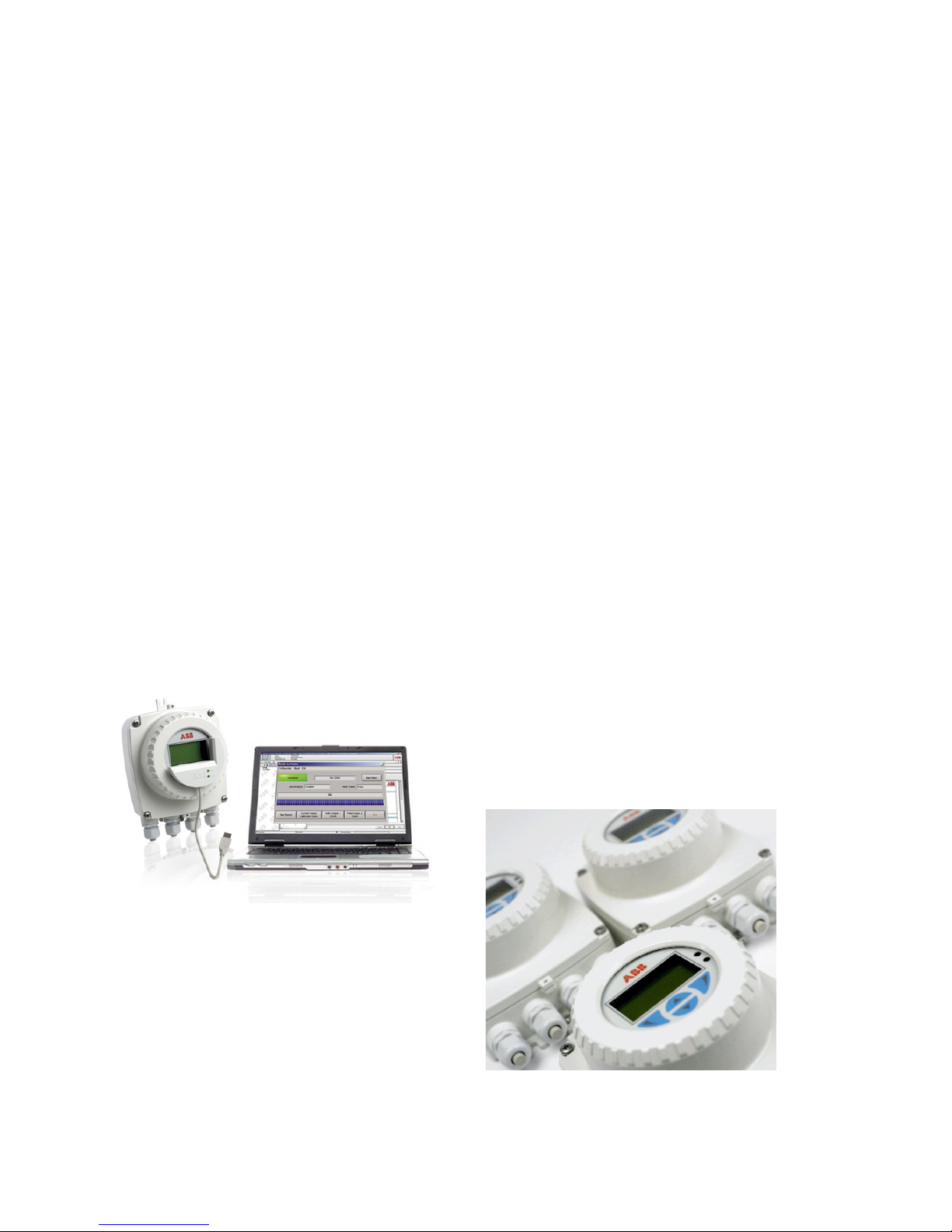
VeriMaster – the verification tool
An easy-to-use utility, available through the infra red service
port. Uses the advanced self-calibration and diagnostic
capability of WaterMaster, coupled with fingerprinting
technology, to determine the accuracy status of the
WaterMaster flowmeter to within ±1 % of its original factory
calibration. VeriMaster also supports printing of calibration
verification records for regulatory compliance.
Diagnostic functions
Using its diagnostic functions, the flowmeter monitors both
its own operability and the process. Limit values for the
diagnostic parameters can be set locally. When these limits
are exceeded, an alarm is tripped. In the event of an error,
diagnostic-dependent help text appears on the display. This
considerably simplifies and accelerates the troubleshooting
procedure.
In accordance with NAMUR NE107, alarms and warnings are
classified with the status of 'Maintenance Required', 'Check
Function', 'Failure' and 'Out of Specification'.
Flow performance
Utilizing its advanced filtering methods, the WaterMaster
improves accuracy even under difficult conditions.
WaterMaster has an operating flow range with ±0.4 %
accuracy as standard (±0.2 % optional) in both forward and
reverse flow directions.
Easy and quick commissioning
'Fit-and-Flow' data storage inside WaterMaster eliminates the
need to match sensor and transmitter in the field. On initial
installation, the self-configuration sequence automatically
replicates into the transmitter all calibration factors, meter
size and serial numbers, as well as customer site-specific
settings, eliminating the potential for error.
Intuitive, convenient navigation
The 'Easy Setup' function reliably guides unpracticed users
through the menu step by step. The smart key based
functionality makes handling a breeze – it's just like using a
cell phone. During configuration, the permissible range of
each parameter is indicated on the display and invalid entries
are rejected.
Universal transmitter – powerful and flexible
The backlit display can be rotated easily without the need for
tools. The contrast is adjustable and the display fully-
configurable. The character size, number of lines and display
resolution (number of decimal points) can be set as required.
In multiplex mode, several different display options can be
pre-configured and invoked one after the other.
The smart modular design of the transmitter unit enables
easy disassembly without the need to unscrew cables or
unplug connectors. HART is used as the standard
communications protocol. Optionally, the transmitter is
available with PROFIBUS DP or MODBUS communication.
Assured quality
WaterMaster is designed and manufactured in accordance
with international quality procedures (ISO 9001) and all
flowmeters are calibrated on nationally-traceable calibration
rigs to provide the end-user with complete assurance of both
quality and performance of the flowmeter.

4
WATERMASTER ELECTROMAGNETIC FLOWMETER | DS/WM-EN REV. Y
—
…Introduction
WaterMaster – always the first choice
WaterMaster sets the standard for the water industry. The
specification, features and user benefits offered by this range
are based on ABB's worldwide experience in this industry and
they are all targeted specifically to the industry's
requirements.
Submersible and buriable
WaterMaster sensors have a rugged, robust construction to
ensure a long, maintenance-free life under the arduous
conditions experienced in the Water and Waste Industry. The
sensors are, as standard, inherently submersible (IP68, NEMA
6P), thus ensuring suitability for installation in chambers and
metering pits that are susceptible to flooding.
A unique feature of the WaterMaster sensors is that sizes
DN40 to DN2400 (1½ to 96 in. NB) are buriable; installation
simply involves excavating to the underground pipe, fitting
the sensor, cabling back to the transmitter and then
backfilling the hole.
The WaterMaster family
Overview of the WaterMaster
A wide range of features and user benefits are built into
WaterMaster as standard:
• bi-directional flow
• unique self-calibrating transmitter (patented) for the
ultimate in stability and repeatability
• OIML-type continuous self-checking, with alarms, ensures
both sensor and transmitter accuracy
• true electrode and coil impedance measurement
• comprehensive simulation mode
• universal switch-mode power supply
(options are available for AC and DC supplies)
• comprehensive self-diagnostics compliant with
NAMUR NE107
• programmable multiple-alarm capability
• bus options: HART (4 to 20 mA), PROFIBUS DP (RS485),
MODBUS (RS485)
• 3 configurable pulse / frequency and alarm outputs
• advanced infrared service port supports remote HMI,
HART, cyclic data out and parameter download
• VeriMaster in situ verification software available as option
• read-only switch and ultra-secure service password for
total security

5
WATERMASTER ELECTROMAGNETIC FLOWMETER | DS/WM-EN REV. Y
OIML / MID approved
WaterMaster has been type tested and Internationally
approved to the highest accuracy class 1 and 2 for cold and
hot potable water meters – OIML R49-1 (Organisation
Internationale de Métrologie Légale). For full details, OIML
R49 is available to download from www.oiml.org. Its
requirements are very similar to other International
standards, such as EN14154 and ISO4064.
WaterMaster has been assessed by type approval at the
National Measurement Office (NMO) to OIML R49 and passed
to the very highest accuracy designations for sizes DN40 to
DN200 (1½ to 8 in. NB).
The approval is for:
• Class 1 and Class 2 accuracy (calibration option)
• Environmental class T50 for water temperatures of
0.1 to 50 °C (32.18 to 122 °F)
• Electromagnetic Environment E2 (10 V/m)
• Any pipe orientation
• 5 Diameters upstream pipe
• 0 Diameters downstream pipe
• Pressure Loss Class <0.25 bar (3.62 psi)
• Integral or remote transmitter (<200 m [<656 ft.] cable)
• DN40 to DN200 (1½ to 8 in. NB), bi-directional flow
A major advance in WaterMaster is the self-checking
capabilities that meet and exceed the R49 requirements and
is the first electromagnetic flowmeter to be approved to
OIML Type P permanent self checking during normal
operation (not just at startup) and alarm indication for:
• transmitter and sensor status, with an accuracy alarm
• program ROM and RAM status
• double, independent storage of totalizer values, in both
the sensor and transmitter non-volatile memories
• display test
The OIML R49-1 certificate of conformity is available from:
http://www.abb.com/product/seitp330/
b42ec2377d3293cdc12573de003db93b.aspx
WaterMaster is also approved under the EU Measuring
Instruments Directive (MID) 2004/22/EC, that covers putting
into use water flowmeters for certain applications. MID
WaterMaster is secured against tamping and is available as an
option, along with fingerprinting for ABB VeriMaster in situ
verification product, with certificate printout to ±1 %
accuracy.
WaterMaster certificates of EC type-examination of a
measuring instrument are available from:
http://www.abb.com/product/seitp330/
b42ec2377d3293cdc12573de003db93b.aspx
Superior control through advanced sensor design
The innovative, patented octagonal sensor design improves
flow profile and reduces up- and down-stream piping
requirements for the most commonly used sizes of 40 to 200
mm (1½ to 8 in.). This optimized full bore meter provides
impressive results in the most difficult of installation
requirements.
WaterMaster sensors are also available in reduced-bore
geometries giving the ultimate in low-flow performance with
a very high turn-down range.
The unique design of the reduced-bore sensor conditions the
flow profile in the measuring section so that distortions in
the flow profile, either upstream or downstream, are
flattened. The result is excellent in situ flowmeter
performance, even with very bad hydraulic installation
conditions.

6
WATERMASTER ELECTROMAGNETIC FLOWMETER | DS/WM-EN REV. Y
—
Specification
WaterMaster specification to OIML R49 Class 1
0.1 (0.44) 1.0 (4.4) 10 (44) 100 (440)
1000 (4402)
Error (%)
Flowrate m3/h (GPM)
Typical meter
performance
±0.2 % ±0.9 mm/s
whichever is the greater
Around Q2 the
performance is
±0.7 mm/s
WaterMaster Class 1
specification
OIML R49 Class 1
accuracy limits
DN100 (4 in. NB)
WaterMaster specification to OIML R49 Class 2
0.1 (0.44) 1.0 (4.4) 10 (44) 100 (440) 1000 (4402)
Error (%)
Typical meter
performance
±0.4 % ±0.9 mm/s
whichever is the greater
Around Q2 the
performance is
±0.7 mm/s
WaterMaster Class 2
specification
OIML R49 Class 2
accuracy limits
DN100 (4 in. NB)
Flowrate m3/h (GPM)
Although OIML R49 does not define the flow accuracy below Q1, WaterMaster continues to measure flow at lower flow rates
down to a cutoff velocity of ±5 mm/s (±0.2 in./s). The accuracy between cutoff and Q1 is typically ±0.9 mm/s (±0.04. in./s).

7
WATERMASTER ELECTROMAGNETIC FLOWMETER | DS/WM-EN REV. Y
WaterMaster optimized full-bore meter (FEV) / full-bore meters (FEF, FEW) flow performance – m3/h
Standard Calibration – 0.4 % Class 2 High Accuracy Calibration – 0.2 % Class 1
DN Q Q
Note: OIML R49–1 allow Class 1 only for meters with Q3 ³ 100 m3/h. Meters outside this range have been tested and conform to
Class 1.

8
WATERMASTER ELECTROMAGNETIC FLOWMETER | DS/WM-EN REV. Y
—
…Specification
WaterMaster optimized full-bore meter (FEV) / full-bore meters (FEF, FEW) flow performance – gal/min
Standard Calibration 0.4 % Class 2 High Accuracy Calibration 0.2 % Class 1
NPS/NB (DN) Q4 Q3 Q0.4% Q2 Q1 Q0.2% Q2 Q1
/
/
/
/
/
/
WaterMaster reduced-bore meter (FER) flow performance – m3/h (gal/min)
Class 2 specification Class 1 specification
Size Q4Q3Q0.4 % Q2Q1
R
Q0.2 % Q2Q1
R
mm in. m3/ h
(Ugal / min)
m3/ h
(Ugal / min)
m3/ h
(Ugal / min)
m3/ h
(Ugal / min)
m3/ h
(Ugal / min)
m3/ h
(Ugal / min)
m3/ h
(Ugal / min)
m3/ h
(Ugal / min)
40 11/231 (138) 25 (110) 0.83 (1.05) 0.063 (0.28) 0.04 (0.18) 630 1.7 (7.48) 0.1 (0.44) 0.063 (0.28) 400
50 2 50 (220) 40 (176) 1.0 (4.40) 0.1 (0.44) 0.063 (0.28) 630 2.0 (8.8) 0.16 (0.7) 0.1 (0.44) 400
65 21/279 (347) 63 (277) 1.6 (7.04) 0.16 (0.7) 0.1 (0.44) 630 3.2 (10.56) 0.25 (1.1) 0.16 (0.7) 400
80 3 125 (550) 100 (440) 2.0 (8.80) 0.25 (1.1) 0.16 (0.7) 630 4.0 (17.6) 0.4 (1.76) 0.25 (1.1) 400
100 4 200 (880) 160 (704) 3.2 (10.56) 0.41 (1.8) 0.25 (1.1) 630 6.4 (28) 0.64 (2.8) 0.4 (1.76) 400
125 5 200 (880) 160 (704) 3.2 (10.56) 0.41 (1.8) 0.25 (1.1) 630 6.4 (28) 0.64 (2.8) 0.4 (1.76) 400
150 6 500 (2200) 400 (1760) 8.0 (35.20) 1.0 (4.4) 0.63 (2.77) 630 16 (70.4) 1.6 (7) 1.0 (4.4) 400
200 8 788 (3470) 630 (2770) 13.0 (57.2) 1.6 (7.04) 1.0 (4.4) 630 25 (110) 2.5 (11) 1.6 (7) 400
250 10 1250 (5500) 1000 (4400) 20 (88) 2.5 (11.01) 1.6 (7) 630 40 (176) 4.0 (17.6) 2.5 (11) 400
300 12 2000 (8810) 1600 (7045) 32 (140.8) 4.1 (18.05) 2.5 (11) 630 64 (281.6) 6.4 (28) 4.0 (17.6) 200
350 14 2000 (8810) 1600 (7045) 32 (140.8) 6.4 (28.18) 4.0 (17.6) 400 64 (281.6) 12.8 (56) 8.0 (35.2) 200
375 15 2000 (8810) 1600 (7045) 32 (140.8) 6.4 (28.18) 4.0 (17.6) 400 64 (281.6) 12.8 (56) 8.0 (35.2) 200
400 16 3125 (13760) 2500 (11007) 50 (220) 10 (44) 6.3 (27.7) 400 100 (440) 20 (88) 12.5 (55) 200
450 18 3125 (13760) 2500 (11007) 50 (220) 10 (44) 6.3 (27.7) 400 100 (440) 20 (88) 12.5 (55) 200
500 20 5000 (22014) 4000 (17610) 80 (352) 16 (70.45) 10 (44) 400 160 (70.4) 32 (141) 20 (88) 200
600 24 7875 (34670) 6300 (27740) 126 (554.4) 25.2 (110.9) 15.8 (70) 400 252 (1108) 50.4 (222) 31.5 (138.7) 200
—

9
WATERMASTER ELECTROMAGNETIC FLOWMETER | DS/WM-EN REV. Y
Specification – Sensor
Functional specification
Temperature limitations
Ambient temperature
Remote transmitter –20 to 70 °C (–4 to 158 °F)
Integral transmitter –20 to 60 °C (–4 to 140 °F)
Process temperature See table below.
0.1 to 50 °C (32.2 to 122 °F)
OIML R49 T50 Approved
Medium temperature °C (°F)
Code Lining Flange material Minimum Maximum
FEF, FEW3 Hard rubber Carbon steel
Stainless steel
FEW1 PTFE Carbon steel
Stainless steel
FEW3 PTFE Carbon steel
Stainless steel
FEW3 Elastomer Carbon steel
Stainless steel
FEF, FER Elastomer Carbon steel
FEV Polypropylene
Pressure limitations
As flange rating
PN25 Max Process Temp 50 °C (122 °F)
PN40 Max Process Temp 40 °C (104 °F)
OIML / MID Approved Meters 16 bar (232 psi)
UL Fire Service approved meters 285 psi
Pressure equipment directive 97/23/EC
This product is applicable in networks for the supply,
distribution and discharge of water and associated
equipment and is therefore exempt.
IP rating
IP68 (NEMA 6) to 7 m (20 ft.) depth
Note. Not sizes DN10 to DN32 (3/8 – 11/4 in. NB)
IP67 (NEMA 4X) – DN10 to DN32 (3/8 – 1¼ in. NB)
Buriable (sensor only)
FEV, FEF and FEW – DN450 to 2400 (18 to 96 in. NB)
to 5 m (16 ft.) depth
Conductivity
>20 µS cm–1
Transmitter mounting
Integral (not FEF) or remote
Electrical connections
20 mm glands
½ in. NPT
20 mm armored glands
Sensor cable
ABB WaterMaster cable available in two forms –
standard and armored
Maximum length 200 m (660 ft.)
Suspended solids
Suspended solids percentage of process medium should
not exceed 6 % of total volume
Physical specification
Wetted parts
Electrode material
Stainless steel 316 L / 316 Ti
Super-austenitic steel
Hastelloy® C-22 and Hastelloy C4
(other electrode materials available on request)
Potential equalizing rings
Minimum of 1 recommended
Lining material / potable water approvals
Potable Water Approvals
Code Size Range Liner WRAS WRAS
60°C ACS DVGW NSF
AZ/
NZS
4020
PTFE
PTFE
Elastomer
Hard
rubber
NSF
approved
material
FEV
Poly-
propylene
FEF
Elastomer
FEF
Hard
rubber
NSF
approved
material
FER
Elastomer
*Size is dependent on flange specification
Lining protection plates
Not required
Installation conditions (recommended)
Straight pipe requirements
Upstream Downstream
FEW / FEF 5 x DN 2 x DN
FEV 5x DN 0 x DN
FER 0 x DN 0 x DN
Pressure loss
Negligible at Q3 All full bore meters
<0.25 bar (<3.62 psi) at Q3 FEV (DN40 to 200
[1½ to 8 in. NB])
<0.63 bar (<9.13 psi) at Q3 FER (DN40 to 600
[1½ to 24in. NB])

10
WATERMASTER ELECTROMAGNETIC FLOWMETER | DS/WM-EN REV. Y
—
…Specification – Sensor
Non-wetted parts
Flange material
Carbon steel DN20 to DN2400 (¾ to 96 in. NB)
SG iron FEV – DN40 to DN150 [1 ½ to 6 in. NB)
FER – DN40 to DN150 [1 ½ to 6 in. NB)
Housing material
Carbon steel FEV – DN40 to 200 (1½ to 8 in. NB)
FEW – DN450 to 2400 (18 to 96 in. NB)
Plastic FEF – DN250 to 600 (10 to 24 in. NB)
Terminal box material
Polycarbonate
Cable gland material
Plastic, brass
Paint specification
RAL 9002 (light grey), in accordance with C4 paint standard

11
WATERMASTER ELECTROMAGNETIC FLOWMETER | DS/WM-EN REV. Y
—
Specification – transmitter
Functional specification
Power supply
Mains 85 to 265 V AC @ <7 VA
Low voltage 24 V AC +10 % /–30 % @ <7 VA
DC 24 V ±30 % @ <0.4 A
Supply voltage fluctuations within the specified range have
no effect on accuracy
Digital Outputs (3)
Maximum output frequency 5250 Hz
1 off dedicated to Alarm / Logic, programmable function
2 off configurable to either Pulse / Frequency or Alarm/
Logic function
Current output – HART FEX100 variant
Maximum loop resistance 750 W
HART protocol Version 5.7 (HART registered)
Signal levels compliant with NAMUR NE 43 (3.8 to 20.5 mA)
Low alarm 3.6 mA, High alarm 21.8 mA
Additional accuracy
±0.1 % of reading
Temperature coefficient: typically <±20 ppm/°C
RS485 Communications – PROFIBUS FEX100-DP variant
Registered name: FEX100-DP
RS485 (9.6kbps to 1.5Mbps), galvanically isolated
DPV0, DPV1
PA Profile 3.01
Standard idents: 9700, 9740, 9741
FEX100-DP specific ident: 3431
3 Concurrent MS2 master connections
RS485 Communications – MODBUS FEX100-MB variant
MODBUS RTU protocol
RS485 (9.6kbps to 115.2kbps), galvanically isolated
Electrical connections
20 mm glands ½ in. NPT, 20 mm armored glands
Temperature limitations
Ambient temperature –20 to 60 °C (–4 to 140 °F)
Temperature coefficient Typically <±10 ppm/°C @
Vel ³0.5 mls
(pulse and current) floating.
Environmental protection
Humidity: 0 to 100 %
Rating: IP67 (NEMA 4X) to 1m (3.3 ft.) depth
Tamper-proof security
Write access prevented by internal switch combined with
external security seals for MID applications
Languages
English, French, German, Italian, Spanish, Polish
Infrared service port
USB adapter (accessory), USB 1.1. and 2.0 compatible
Driver software for Windows 2000, XP, 7 (32-bit) and Vista
Housing material
Powder-coated aluminium with glass window
Paint specification
Paint coat ³70 µm thick RAL 9002 (light grey)
Transmitter vibration testing
Vibration level: 7 m/s2
Frequency range: 20 to 150 Hz
No. of sweeps in 3 orthogonal planes: 20
Undetectable shift in transmitter span or zero performance
Hazardous approvals
FM & FMc Class 1 Div 2
(FM listing NI / 1 / 2 / ABCD / T4, S / II, III / 2 / FG /T4,
Ta=60C; Type 4X, IP67 – for transmitter and integral
mounting
Ta=70C, Type 6P, IP68 – for remote sensor type,
IP67 on DN10 to 32 [3/8 to 11/4 in.NB])
(FMc listing NI / 1 / 2 / ABCD / T4, DIP / II, III / 2 / FG /T4,
Ta=60C; Type 4X, IP67 – for transmitter and integral
mounting
Ta=70C, Type 6P, IP68 – for remote sensor type, IP67 on
DN10 to 32 [3/8 to 11/4 in.NB])
only
*Size is dependent on flange specification
II 3 G Ex nA IIC T5 Gc
II 2 D Ex tb IIIC T100°C Db
TA = –20°C to +60°C (integral transmitter)
TA = –20°C to +70°C (remote sensor)
Ex tb IIIC T100°C Db
Ex nA IIC T5 Gc
TA = –20°C to +60°C (integral transmitter)
TA = –20°C to +70°C (remote sensor)
*FEW, FEV, FET and FEF ³700 (27/28 in. NB) only
Declaration of Conformance
Copies of CE certification will be available on request.
WaterMaster has OIML R49 Certificate of Conformity to
accuracy class 1 and 2 (FEV DN40 to 200 [1½ to 8 in.NB]).
Copies of accuracy certification are available on request.
WaterMaster (FEV DN40 to 200 [1½ to 8 in.NB]) has been
type examined under directive MID 2004/22/EC, Annex MI-
001. Copies of this certificate are available on request.

12
WATERMASTER ELECTROMAGNETIC FLOWMETER | DS/WM-EN REV. Y
—
Transmitter connections
Transmitter terminal connections overview
This section is intended to give an overview of installation of a flowmeter. For Installation requirements, technical information
and Health and safety precautions – refer to the User Guide OI/FET100–EN.
AC / DC Power
supply terminal
Test points for
output connections
Sensor
cable terminal
Output
connections terminal
Internal earth
(alternative PE)
Sensor cable
Output
connections
External earth
Output
connections
Backplane
Internal earth
(alternative PE)
Power cable
Cable gland / conduit entry (Remote transmitter shown)
Sensor cable terminal connections and recommended cable lengths
connect the drain wire to terminal SCR.
See above for cable preparation requirements
before connecting cable
with screen from
D1/TFE – Orange
and D2 – Yellow)
Cut cables to 70 mm (2.75 in.) Cut cables to 60 mm (2.35 in.)
M1
Brown
M2
Red
D1/TFE
Orange
SCR
Screen
D2
Yellow
3
Green
(Sleeve)
S2
Blue
(Screen)
E2
Blue
(Signal)
E1
Violet
(Signal)
S1
Violet
(Screen)
Sensor cable connections at transmitter terminal block – remote transmitter

13
WATERMASTER ELECTROMAGNETIC FLOWMETER | DS/WM-EN REV. Y
Power supply connections
AC power supply
Power supply indicator LED
(see table below for suppliers)
AC power via a suitable
isolator and fuse >4 mm2(<10 AWG) Copper wire
Transmitter label
External earth screw
Protective Earth (PE)
if required by
national standards
Fuse supplier Fuse part number
ABB B20411
Bussmann BK/ETF 250 mA
Wickmann 19372 K250mA
Brown
Blue
Green / Yellow
AC power supply connections
DC (and low voltage AC) power supply
Power supply indicator LED
(see table below for suppliers)
>4 mm2(<10 AWG) Copper wire
DC (or low voltage AC) power
via suitable isolator and fuse
Transmitter label
External earth screw
Internal earth screws
Fuse supplier Fuse part number
ABB B20412
Bussmann BK/ETF 2A
Wickmann 19372 K2A
Red
Black
Green / Yellow
DC (and low voltage AC) power supply connections

14
WATERMASTER ELECTROMAGNETIC FLOWMETER | DS/WM-EN REV. Y
—
…Transmitter connections
Configuration DIP switches
Three configuration DIP switches are mounted on the
transmitter backplane board.
These are factory-set as follows:
• Remote transmitter – all OFF
• Integral transmitter – SW3 ON
For MID-compliant flowmeters the read-only / MID protection
switch is set to 'ON' to ensure the meter is secure from
tampering.
For HART software versions prior to 01.02.XX, this switch (set
after commissioning) prevents login via the keypad or bus at
any security level.
From HART software version 01.03.XX onwards and for all
PROFIBUS software versions, on MID meters, all metrological-
related parameters are locked and inaccessible at the Service
level. Standard and Advanced user level parameters can still
be modified via the HMI or bus.
Configuration
DIP switches
OFF
ON
SW3 SW2 SW1
DIP Switch functions
SW1 – Read-only / MID Protection
SW2 – (future product)
SW3 – Internal sensor memory
Configuration DIP switches
Transmitter module identification
Note. The communications bus type is HART FEX100 if not
specified on the transmitter module label. An example of the
PROFIBUS FEX100-DP variant transmitter module label is
shown below.
PROFIBUS FEX-100P label
Black label on AC converter module
Red label on DC
(and low voltage AC)
converter module
Transmitter module identification

15
WATERMASTER ELECTROMAGNETIC FLOWMETER | DS/WM-EN REV. Y
—
Output connections
Frequency outputs
XX XX XX XX 42 41 51 61
52
62
Terminal connection IDs
are HART- / PROFIBUS-
variant dependent
COM DO1 DO2
PLC or Datalogger
PLC / Datalogger connections
Note. Digital outputs DO1 and DO2 are polarity sensitive. The
common (negative) connection for these outputs is
designated 'COM'.
+–
123456
123456
XX XX XX XX 42 41 51 61
52
62
COM DO1 DO2
Forward flow output (DO1)
Counter / Totalizer
Reverse flow
output (DO2)
Counter / Totalizer
DC Supply
and/or
Electromechanical connections
123456
123456
XX XX XX XX 42 41 51 61
52
62
+–
+–
COM DO1 DO2
Forward flow output (DO1)
Counter / Totalizer
and/or
Reverse flow
output (DO2)
Counter / Totalizer
Telemetry / Electronic counters connections
Alarm outputs
Terminal connection IDs
are HART- / PROFIBUS- /
MODBUS- variant dependent
COM DO3
XX XX XX XX 42 41 51 61
52
62
+
–
COM DO1 DO2 DO3
DC supply
Horn
Alarm 1
Alarm 2
Bell
and/ or
Note.
• Normal alarm / logic output is from DO3 (terminal 61). DO1
(41) and DO2 (51) can also be configured as alarms if
required but are then NOT available as frequency / pulse
outputs as shown in Electromechanical connections and
Telemetry / Electronic counters connections, opposite.
• Bell and horn shown for example only. Any suitable alarm
device may be used (for example, lamp, siren, buzzer etc.).
XX XX XX XX 42 41 51 61
52
62
+
–
COM DO1 DO2
DC supply
Timer switch
Alarm 1
Alarm 2
Relay
and/ or
Note. Relay and timer switch shown for example only.

16
WATERMASTER ELECTROMAGNETIC FLOWMETER | DS/WM-EN REV. Y
—
…Output connections
PLC interface
XX XX XX XX 42 41 51 61
52
62
+
–
COM DO1 DO2
DC supply
PLC
Typically
1kW
1W
24 V
Com
Fwd +
Rev +
XX XX XX XX 42 41 51 61
52
62
+
–
COM DO1 DO2
DC supply
PLC
Com
Fwd – Rev –
Note.
• WaterMaster digital outputs are NPN optocoupled
transistors used as switches.
• Maximum allowed voltage at collector is 30 V DC
• Maximum allowed current across transistor is 220 mA.
Current output (4 to 20 mA) – HART (FEX100) variant
+–
Refer to IM/WMP for HART-Protocol
communication details
Current output (4 to 20 mA) – HART (FEX100) variant
RS485 communications – PROFIBUS (FEX100-DP) and
MODBUS (FEX100-MB) variants
PROFIBUS / MODBUS RS485
A1 / B1 – In
A2 / B2 – Out
Screen clamp
Test point access
Note. A typical DVM probe can access (fit) the PCB's test
holes.
IC+ IC–
O/P1
O/P2
COM
4 to 20 mA
Frequency
outputs
Not used
Not used
O/P3 Alarm output
backplane only (they are present on the PROFIBUS
FEX100-DP / MODBUS FEX100-MB backplane but not
connected)

17
WATERMASTER ELECTROMAGNETIC FLOWMETER | DS/WM-EN REV. Y
—
Digital communication
The transmitter has the following options for digital communication.
HART protocol
The unit is registered with HART Communication Foundation.
Multidrop connection
HART Connections
at terminal block
4 mA Current output
(multidrop connection)
4 to 20 mA current output
(single connection) –
see User Guide IM/WMP
Sensor
HART FSK-Modem
or handheld terminal
PC connection
(USB or RS232)
Single
connection
250 Wminimum load
HART protocol
Configuration Directly on the Device
Software Asset Vision Basic (+ HART – DTM)
Transmission
Install a HART modem (FSK [Frequency Shift
Keyed]-Modem) for HART-Communication
when connecting to a PC. The HART-Modem
connector
Max. signal amplitude
Current output load
Cable
Max. cable length
Baud rate
System integration
WaterMaster can be integrated into control systems and
configuration devices using any Frame application, such as
ABB AssetVision or similar third-party applications. ABB
Device Type Managers (DTMs) for WaterMaster provide a
unified structure for accessing device parameters,
configuring and operating the devices and diagnosing
problems. FDT (Field Device Tool) technology standardizes
the communication and configuration interface between all
field devices and host systems.
PROFIBUS DP protocol
PROFIBUS is a manufacturer-independent, open Fieldbus
standard for a wide range of applications in manufacturing,
process and building automation. Manufacturer
independence and openness are ensured by the international
standard EN 50170.
PROFIBUS DP ID no. 0x3431
Alternative standard ID no.
Configuration Directly on the device
Software Asset Vision Basic
(+PROFIBUS DP-DTM)
Transmission signal
Cable Shielded, twisted cable
All devices are connected in a bus structure ('line') as shown in
below. Up to 32 stations (master or slaves) can be linked to
create one 'segment', although it is recommended not to
install more than 16 devices on a single segment. Each end of
a segment must be terminated by an active bus terminating
resistor. Both bus terminators must always be powered to
ensure fault-free operation, therefore it is strongly
recommended that they are connected to a back-up power
supply. The use of bus amplifiers (repeaters) and segment
couplers can be used to extend the network.
Operational
level
Engineer Operate
Control
WaterMaster
FEX100-DP
DP /
PA Link
PROFIBUS-DP
PROFIBUS-PA
Master
level
Slave
level

18
WATERMASTER ELECTROMAGNETIC FLOWMETER | DS/WM-EN REV. Y
—
…Digital communication
System integration
The GSD file for WaterMasters specifies the device-specific
Ident No. 3431. It conforms to the PROFIBUS standard,
providing a clear and comprehensive description of each
instrument in a precisely defined format.
This enables the system configuration tool to use the
information automatically when configuring a PROFIBUS bus
system.
The ABB GSD file (Ident No. 3431) is divided into 2 sections:
• General specifications
– Identification of the device, together with hardware
and software versions, baud rates supported and the
possible time intervals for monitoring times.
• DP slave-related specifications
– Information about the user parameter block for de-
vice-specific configuration and modules containing de-
tails of the input and output data that can be ex-
changed cyclically with a PROFIBUS master.
The WaterMaster GSD file (ABB_3431.gsd) is available for
download from the ABB website at: www.abb.com/fieldbus
(follow the link for PROFIBUS DP field devices).
MODBUS protocol
MODBUS is an open standard that is owned and administered
by an independent group of device manufacturers called the
Modbus Organization (www.modbus.org).
Using the MODBUS protocol, devices from different
manufacturers exchange information on the same
communications bus without the need for special interface
equipment. WaterMaster FEX100-MB follows the specification
for Modbus Over Serial Line V1.02, using 2-wire TIA/EIA-485
(RS485) physical layer.
Line
terminator
Pull
down
Pull
up
Balanced pair
Slave 1
For example, WaterMaster FEX100–MOD
Slave n
Common
D1
D0
D
D D
R
R R
Line
5 V
Up to 31 slaves
Master
Cable Properties
The end-to-end length of the trunk cable must be limited. The
maximum length depends on the Baud rate, the cable (gauge,
capacitance or characteristic impedance), the number of
loads on the daisy chain and the network configuration (2-
wire or 4-wire).
For 9600 Baud rate and AWG26 (or wider) gauge, the
maximum length is 1000 m (3280 ft.). Where 4-wire cabling is
used as a 2-wire cabling system the maximum length must be
divided by 2. The tap cables must be short, never more than
20 m (65.6 ft.). If a multi-port tap is used with n derivations,
each one must have a maximum length of 40 m (131 ft.)
divided by n.
The maximum serial data transmission line length for RS485
systems is 1200 m (3937 ft.). The lengths of cable that can be
used are determined by the cable type, typically:
• Up to 6 m (19.7 ft.) – standard screened or twisted pair
cable.
• Up to 300 m (984 ft.) – twin twisted pair with overall foil
screen and an integral drain wire – for example, Belden
9502 or equivalent.
• Up to 1200 m (3937 ft.) – twin twisted pair with separate
foil screens and integral drain wires – for example, Belden
9729 or equivalent.
Category 5 cables may be used for RS485-MODBUS to a
maximum length of 600 m (1968 ft.). For the balanced pairs
used in an RS485-system, a characteristic impedance with
value higher than 100W is preferred especially for 19200 and
higher Baud rates.

19
WATERMASTER ELECTROMAGNETIC FLOWMETER | DS/WM-EN REV. Y
—
Installation requirements
This section is intended to give an overview of installation of
a flowmeter. For Installation requirements, technical
information and Health and Safety precautions refer to User
Guide OI/FEF/FEV/FEW–EN.
Unpacking the flowmeter
Care must be taken when lifting the flowmeter to use the
lifting hooks provided or sling under the body of the meter.
Never lift using the terminal connection box of the sensor
cable as this will cause damage and invalidate warranty.
Sling angle <90°
Grounding
The flowmeter sensor must be cross-bonded to the upstream
and downstream pipes. For technical reasons, this potential
should be identical to the potential of the metering fluid. The
fluid connection is made by installing 2 fluid contact rings (for
grounding).
Fluid contact rings
Mounting
The installation conditions shown below must be observed to
achieve the best operational results.
The sensor tube must always be completely full.
The flow direction must correspond to the identification
plate. The device measures the flowrate in both directions.
Forward flow is the factory setting.
The devices must be installed without mechanical tension
(torsion, bending). If required support the pipeline.
Supports
The flange seals must be made from a compatible material
for the fluid and fluid temperatures if required.
20 °C
(– 4 °F)
Min.
70 / 130 °C
(158 / 266 °F)
Max.
Seals must not extend into the flow area since possible
turbulence could influence the device accuracy.
Fit gaskets
Gaskets same size as pipe

20
WATERMASTER ELECTROMAGNETIC FLOWMETER | DS/WM-EN REV. Y
—
…Installation requirements
The pipeline may not exert any unallowable forces and
torques on the device, such as vibration.
The flowmeter must not be submitted to any localized heat
during installation; take care to remember this is a measuring
instrument.
The flowmeter must not be exposed to direct sunlight or
provide for appropriate sun protection where necessary.
The cable to the flowmeter should be installed neatly or
within a conduit, both loose or conduit should have a u shape
below the terminal connection box height to allow any water
run off to avoid any capillary action into the flowmeter sensor.
Ensure a maximum 6 % dry solids content flow through pipe –
for higher dry solids content, refer to ABB’s ProcessMaster
range.
Electrode axis
Electrode axis should be horizontal if at all possible or no
more than 45° from horizontal.
45 ° Max.
Upstream and Downstream pipe sections
The metering principle is tolerant of the flow profile.
• Wherever possible do not install fittings (for example,
manifolds, valves) directly in front of the flowmeter sensor.
• Butterfly valves should be installed so that the valve plate
does not extend into the flowmeter sensor.
• Valves or other turn-off components should be installed in
the Downstream pipe section.
Experience has shown that, in most installations, straight
upstream sections 3 x DN long and straight downstream
sections 2 x DN long are normally sufficient. We would
recommend conditions of 5 x DN straight upstream and 2 x
DN straight downstream where possible.
For reduced-bore meters (FER), these straight pipe sections
are often not necessary.
5 x DN (FEW, FEF)
0 x DN (FER)
5 x DN (FEV)
2 x DN (FEW, FEF)
0 x DN (FER)
0 x DN (FEV)
≤6 % (max.)
dry solids
Other manuals for WaterMaster
2
Table of contents
Other ABB Measuring Instrument manuals

ABB
ABB C13 User manual

ABB
ABB ScreenMaster RVG200 Original operating manual

ABB
ABB Sensyflow FMT400-VTS Training manual

ABB
ABB IM300-I Quick start guide

ABB
ABB MicroGuard solution User manual

ABB
ABB EXCOUNT-II User manual

ABB
ABB GLA232 Series User manual

ABB
ABB Advance Optima Caldos 15-Ex User manual

ABB
ABB PointMaster 200 Series User manual

ABB
ABB PGC1000 User manual