ABB IM/SM3000 User manual

InformIT
Multipoint Videographic Recorder
SM3000
User Guide
IM/SM3000

ABB
The Company
We are an established world force in the design and manufacture of instrumentation for industrial
process control, flow measurement, gas and liquid analysis and environmental applications.
As a part of ABB, a world leader in process automation technology, we offer customers
application expertise, service and support worldwide.
We are committed to teamwork, high quality manufacturing, advanced technology and unrivalled
service and support.
The quality, accuracy and performance of the Company’s products result from over 100 years
experience, combined with a continuous program of innovative design and development to
incorporate the latest technology.
The NAMAS Calibration Laboratory No. 0255 is just one of the ten flow calibration plants
operated by the Company, and is indicative of our dedication to quality
and accuracy.
Warning – Refer to the manual for instructions
Caution – Risk of electric shock
Protective earth (ground) terminal
Earth (ground) terminal
Direct current supply only
Alternating current supply only
Both direct and alternating current supply
The equipment is protected
through double insulation
Electrical Safety
This instrument complies with the requirements of CEI/IEC 61010-1:2001-2 'Safety Requirements for Electrical Equipment for
Measurement, Control and Laboratory Use'. If the instrument is used in a manner NOT specified by the Company, the protection
provided by the instrument may be impaired.
Symbols
One or more of the following symbols may appear on the instrument labelling:
Information in this manual is intended only to assist our customers in the efficient operation of our equipment. Use of this manual for
any other purpose is specifically prohibited and its contents are not to be reproduced in full or part without prior approval of the
Technical Publications Department.
Health and Safety
To ensure that our products are safe and without risk to health, the following points must be noted:
1. The relevant sections of these instructions must be read carefully before proceeding.
2. Warning labels on containers and packages must be observed.
3. Installation, operation, maintenance and servicing must only be carried out by suitably trained personnel and in accordance with the
information given.
4. Normal safety precautions must be taken to avoid the possibility of an accident occurring when operating in conditions of high pressure and/
or temperature.
5. Chemicals must be stored away from heat, protected from temperature extremes and powders kept dry. Normal safe handling procedures
must be used.
6. When disposing of chemicals ensure that no two chemicals are mixed.
Safety advice concerning the use of the equipment described in this manual or any relevant hazard data sheets (where applicable) may be
obtained from the Company address on the back cover, together with servicing and spares information.
EN ISO 9001:1994
Cert. No. Q05907
EN 29001 (ISO 9001)
Lenno, Italy – Cert. No. 9/90A
0255
Stonehouse, U.K.

1
Shunt Resistors
(1 per analog input)
Mounting Clamps (x4)
Keys
CONTENTS
1INTRODUCTION .............................................................. 2
2OPERATION ..................................................................... 3
2.1 Powering Up the Instrument .............................................. 3
2.2 Displays and Controls ....................................................... 3
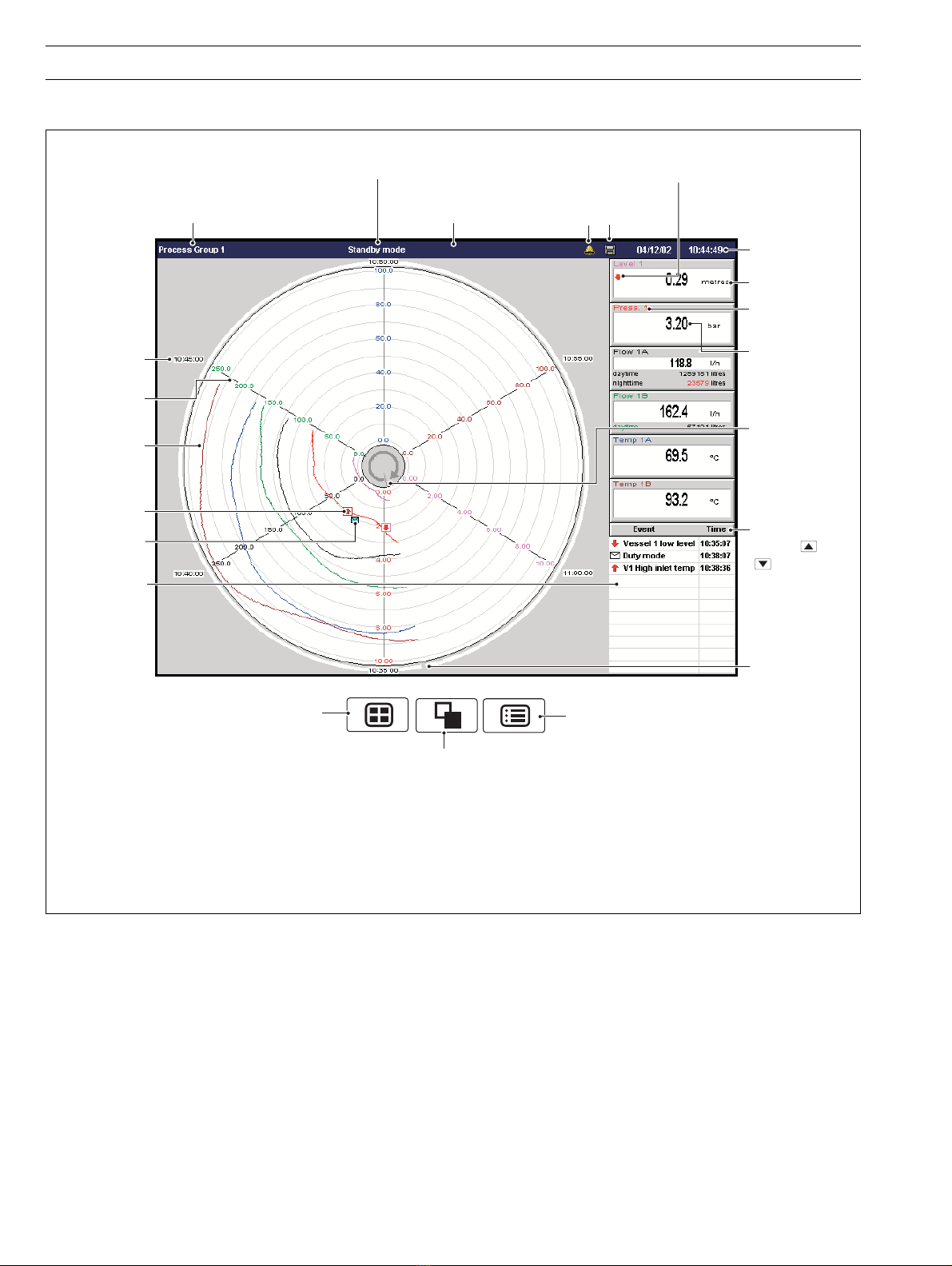
2.3 Chart Views ....................................................................... 5
2.3.1 Electronic Signatures .......................................... 13
2.4 Bargraph Views ............................................................... 14
2.5 Digital Indicator View ....................................................... 16
2.6 Process View .................................................................. 19
2.7 Instrument Status / Audit Log View ................................. 21
2.7.1 Instrument Status View ....................................... 22
2.7.2 Audit Log View ................................................... 23
2.8 Alarm Event Log .............................................................. 24
2.9 Totalizer Log .................................................................... 26
3SETUP ............................................................................ 28
3.1 Introduction ..................................................................... 28
3.2 Accessing the Setup Level .............................................. 28
3.3 Password Entry ............................................................... 29
3.4 Setup Menu .................................................................... 30
3.5 Archiving ......................................................................... 32
3.5.1 SmartMedia Handling and Care .......................... 32
3.5.2 Media Status ...................................................... 32
3.5.3 Inserting and Removing Media ........................... 33
3.5.4 Archive File Types ............................................... 34
3.5.5 Archive Filenames ............................................... 34
3.5.6 Channel Data Files .............................................. 34
3.5.7 Log files .............................................................. 35
3.5.8 On-line/Off-line ................................................... 35
3.5.9 Data Verification and Integrity.............................. 35
3.5.10 Backing Up Archived Data .................................. 35
3.5.11 File Formats ........................................................ 36
4CONFIGURATION .......................................................... 38
4.1 Introduction ..................................................................... 38
4.1.1 Configuration Level Security ............................... 38
4.1.2 Configuration Level Access ................................ 38
4.2 Overview of Configuration ............................................... 41
4.3 Making Changes to Parameters ...................................... 42
4.4 Common Configuration ................................................... 48
4.4.1 Setup ................................................................. 48
4.4.2 Security .............................................................. 51
4.4.3 Logs ................................................................... 53
4.4.4 Operator Messages ............................................ 53
4.4.5 Ethernet ............................................................. 54
4.4.6 e-mail ................................................................. 55
4.5 Process Group Configuration .......................................... 57
4.5.1 Setting the Recording Parameters ...................... 57
4.5.2 Configuring the Chart View ................................. 59
4.5.3 Configuring the Bargraph View ........................... 61
4.5.4 Configuring the Process View ............................. 62
4.5.5 Configuring the Digital Indicator View .................. 63
4.5.6 Archiving ............................................................ 65
4.6 Channel Configuration ..................................................... 66
4.6.1 Recording Channel Setup ................................... 67
4.6.2 Analog Input Configuration ................................. 69
4.6.3 Digital Input Configuration ................................... 71
4.6.4 Alarm Configuration ............................................ 72
4.6.5 Totalizer Configuration ........................................ 77
4.7 I/O Module Configuration ................................................ 80
4.7.1 Analog Inputs ..................................................... 80
4.7.2 Relay Modules .................................................... 81
4.7.3 Hybrid Modules .................................................. 82
4.7.4 RS485 (Modbus) Modules .................................. 83
4.8 Functions ........................................................................ 84
4.8.1 Custom Linearizers ............................................. 84
4.8.2 Real-time Alarms ................................................ 85
5INSTALLATION .............................................................. 86
5.1 Siting ............................................................................... 86
5.2 Mounting ......................................................................... 87
5.3 Electrical Connections ..................................................... 88
5.4 Analog Inputs .................................................................. 90
5.4.1 Current and Voltage ............................................ 90
5.4.2 Thermocouple .................................................... 90
5.4.3 Resistance Thermometer (RTD) .......................... 90
5.4.4 Transmitter Power Supply ................................... 90
5.5 Mains Power Connections ............................................... 91
5.6 Relay Output Board Connections .................................... 91
5.7 Hybrid I/O Module Connections ...................................... 92
5.7.1 Digital Output Connections ................................. 92
5.7.2 Digital Input Connections .................................... 92
5.7.3 Analog Output Connections ............................... 92
5.8 Ethernet Network Connections ........................................ 93
5.8.1 Direct Connection to a Computer ....................... 93
5.8.2 Connection to a Network Hub ............................ 94
5.8.3 Connection to a Dial-Up Router .......................... 94
5.8.4 Connection to an Internet Gateway .................... 94
APPENDIX 1 – SIGNAL SOURCES .................................... 95
APPENDIX 2 – STORAGE CAPACITY ................................ 96
A2.1 Internal Storage Capacity ................................................ 96
A2.2 Archive Storage Capacity ................................................ 97
APPENDIX 3 – DEFAULT SETTINGS ................................. 98
A3.1 Company Standard ......................................................... 98
A3.1.1 Common Configuration ...................................... 98
A3.1.2 Process Groups 1 to 6 ....................................... 98
A3.1.3 Recording Channels ........................................... 99
A3.1.4 I/O Modules ........................................................ 99
A3.1.5 Functions ......................................................... 100
A3.2 QuickStart Templates .................................................... 100
A3.2.1 QSMilliAmp ....................................................... 100
A3.2.2 QSFlow ............................................................ 100
A3.2.3 QSTHC_C ........................................................ 100
A3.2.4 QSTHC_F ......................................................... 100
A3.2.5 QSRTD_C ........................................................ 101
A3.2.6 QSRTD_F ......................................................... 101
A3.2.7 QSDEMO ......................................................... 101
APPENDIX 4 – ETHERNET ............................................... 102
A4.1 Introduction ................................................................... 102
A4.2 Testing a Network Connection ....................................... 103
A4.3 Configuring FTP Access ................................................ 103
A4.4 Using the Instrument's Web Server ............................... 107
A4.5 Glossary of Terms ......................................................... 112
APPENDIX 5 – SPARE PARTS & ACCESSORIES ........... 113
APPENDIX 6 – ERROR &
DIAGNOSTICS INFORMATION ........................................ 114
INDEX ................................................................................ 115
Standard Accessories
Note. For optional accessories, refer to APPENDIX 5.

2
Instrument Logs
2.1
2.2
2.3
2.4
2.5
2.6
Process Group 1
1.1
1.2
1.3
1.4
1.5
1.6
Recording
Channels
1.1 to 1.6
A1
A2
A3
A4
A5
A6
Analog Inputs A to F
F1
F2
F3
F4
F5
F6
1
2
3
24
Comms.
Analog Inputs
C1
C2
C3
C4
C5
C6
Digital Inputs
Configuration
Data
Recording
Channels
2.1 to 2.6
Process Group 2 (Process Groups 3 to 6 similar)
Note. Signal sources
can be assigned to any
recording channel in any
process group.
Chart View (Section 2.3)
Digital Indicator View (Section 2.5)
Bargraph View (Section 2.4)
Process View (Section 2.6)
Recorded Data
Archive Media
Data saved to archive
storage media
Signal Sources
•Up to 6 process groups as
standard provide up to 36
recording channels, divided
equally between each group,
irrespective of the number of
external inputs.
Chart View Digital Indicator ViewBargraph View Process View
Alarm Event Log (Section 2.8) Totalizer Log (Section 2.9)
•Views provide a window on the stored data.
Archive Data
Files stored in instrument's
on-board flash memory.
Newest data overwrites
oldest.
Configuration Data
Stores all
instrument
configuration,
calibration and
user preferences
1
2
3
24
Comms.
Digital Inputs
D1
D2
D3
D4
D5
D6
Internal sources –
see Appendix 1
•Status and Audit Log View (Section 2.9)
Recording Channels 5.1 to 5.6
(Process Group 5)
Recording Channels 6.1 to 6.6
(Process Group 6)
Instrument Logs
Configuration Data
Recording Channels 1.1 to 1.6
(Process Group 1)
Recording Channels 2.1 to 2.6
(Process Group 2)
Recording Channels 3.1 to 3.6
(Process Group 3)
Recording Channels 4.1 to 4.6
(Process Group 4)
Alarm/Event Log
Totalizer Log
Audit Log
Records all alarm
transistions and all
operator messages
Records all totalizer
activity
Records all system
acfivity
1INTRODUCTION
Fig. 1.1 Functional Overview
•Any source can be assigned to any recording channel.
•Data from assigned sources can be displayed in:
–Vertical-, Horizontal- or Circular-Chart view format
–Vertical or Horizontal Bargraph view format
–Digital Indicator view format
–Process view format
•Three instrument logs record alarm events, totalizer values
and system/configuration changes.
Functional Overview – Fig. 1.1.
•36 Recording Channels as standard, equally divided into up
to 6 Process Groups, each with up to a maximum of 12
Recording Channels.
•Four Alarms and two Totalizers are assigned to each
Recording Channel.
•Signal sources derived from universal analog inputs, the
optional Modbus serial link, optional digital inputs or internal
analog and digital signals.

3
Group Key
Selects a different
process group
Process Group 1
Instrument Status & Logs
Process Group 2
Process Group 3
Process Group 4
Process Group 5
Process Group 6
View Key
Selects a different process view
or log
Menu Key
Displays or hides the context-sensitive operator
menu associated with each view
Chart View –
see Section 2.3
Bargraph Views –
see Section 2.4
Digital Indicator
View – see
Section 2.5
Process View – see Section 2.6
Also cancels the menu without making a
change or returns to the previous menu level
Up/Down Keys
Highlights menu items and scrolls through
previously recorded data
Left/Right Keys
Scrolls through previously recorded data
Enter Key
Selects the highlighted menu item
Short Channel Tag
Current Value
Engineering Units
Media Door
Status Icons –
see inside rear fold-out
Programming Socket (Inside Door) Door Lock Jacking Screw and Fitting for Tamper-proof Seal
Operator Keys
Process Group Name
Digital ON or OFF tag,
according to input status
Current
Date and Time
2OPERATION
Fig. 2.1 Displays and Controls
2.1 Powering Up the Instrument
When power is first applied to the instrument, its processor carries out a number of self-tests and displays the start-up screen.
At the end of the start up sequence the instrument displays the last Operator View that was displayed when the instrument was
powered down.
2.2 Displays and Controls – Figs. 2.1 and 2.2
In normal day-to-day use, the instrument is operated via the Operator Keys located along the bottom of the screen.

4
Process Group 1
Instrument Status & Logs
Process Group 2
Process Group 3
Process Group 4
Process Group 5
Process Group 6
…2 OPERATION
Note. Only process groups
and views that have been
enabled are displayed – see
Section 4.5, Process Group
Configuration.
Fig. 2.2 Overview of Operator Displays
…2.2 Displays and Controls – Figs. 2.1 and 2.2

5
15:04:21 Duty ON, Standby OFF
For a description of the Status Icons (displayed in the Status Bar) and Alarm Event Icons
(displayed in the Bargraph, Digital Indicators, Process and Chart Views), refer to the Rear Foldout.
Newest Data
Oldest Data
Newest Data Oldest Data
Short Channel Tag
Current Value
(see
Note 1
on Page 7)
Scale Bar
Alarm Event Annotation
(see
Note 3
on Page 7)
Operator Message Annotation
(see
Note 3
on Page 7)
Alarm Event Icon (see
Note 2
on Page 7)
Group Tag
Units
Status Bar Status Icon
Current Date and Time
Screen Interval
Time Stamp
Chart Trace
Selects next Process Group
(if enabled) or Status View Opens the Operator Menu for
the current view
Digital On/Off Tag
Screen Interval
Operator Message
(appears for 1 second)
15:07:39 High Out Flow Rate
15:02:51 High Level
Channel Not Used
Alarm Indication
(Flashing red border and
alarm event icon indicates
alarm unacknowledged.
Continuous alarm event icon
indicates alarm acknowledged)
Selects the next enabled
view in the group
(Bar, Digital or Process)
Global Alarm
Status Icon
(see
Note 2
on Page 7)
2OPERATION…
Note. Do not remove media while the media update in progress status icon is displayed.
Fig. 2.3 Horizontal and Vertical Chart Views
2.3 Chart Views (Horizontal and Vertical – Fig. 2.3)

6
…2.3 Chart Views (Circular – Fig. 2.4)
…2 OPERATION
Event Log.
Use the and
keys to scroll
through the log
entries
Short Channel
Tag
Scale Bar
Alarm Event Icon
(see
Note 2
on Page 7)
Group Tag
Units
Status Bar Status Icon
Current Date
and Time
Time Stamp
Chart Trace
Recording
Started
Indicator
Current Value
(see
Note 1
on
Page 7)
Alarm Event
and
Operator
Message
Annotation
(see Event Log
and
Note 3
on Page 7)
Operator Message
(appears for 1 second)
For a description of the Status Icons (displayed in the Status Bar) and Alarm Event Icons
(displayed in the Bargraph, Digital Indicators, Process and Chart Views), refer to the Rear Foldout.
Recording
Started and
Direction of
Rotation
Indicator
Selects next Process Group
(if enabled) or Status View
Selects the next enabled
view in the group
(Bar, Digital or Process)
Opens the Operator Menu for
the current view
Global Alarm
Status Icon
Fig. 2.4 Circular Chart View

7
Configuration
Setup
Sign Chart
Historical Review
Values displayed
indicate the process
status at the cursor
position
Cursor
Historical Review Active Invalid data – e.g. recording disabled
Digital
Indicators
11:57:30 High Level
11:58:23 Duty/Standby Pumps Switched
2OPERATION…
Select the Configuration Level – see Section 4.
Select the Setup Level – see Section 3.
Sign the chart electronically – see Section 2.3.1.
Select Historical Review to view previously recorded data stored in the instrument's
onboard memory.
Note. Use the and keys (Horizontal and Vertical Chart view) or and keys
(Circular Chart view) to move backwards and forwards through the recorded data.
…2.3 Chart Views
Notes.
1. Current Values
The Current Value, shown on the digital indicators at either the top (vertical chart view) or right hand side (horizontal chart
view) of the screen, is the latest instantaneous value and its update rate is not affected by the recording sample rate.
If the current value in the digital indicator is displayed in red, recording has been stopped for that channel – see Sections 3.4
and 4.5.1.
Traces are shown only when that particular channel is being recorded. When a channel is set to Stop, its trace continues
to be shown for up to one sample period.
2. Alarm Status
•Flashing red border around channel indicator alternating with flashing red alarm event icon – alarm active and
unacknowledged
•Continuous red alarm event icon – alarm active and acknowledged
If any alarm in any process group is active, the Global Alarm status icon ( ) is displayed in the status bar – see
Fig. 2.3. If any active alarm in any process group is unacknowledged, the icon is surrounded by a red flashing border.
3. Alarm Event and Operator Message Annotations
Alarm Event and Operator Message annotations are not shown on the chart unless enabled – see 'Chart Annotation' on
page 9 and Section 4.5.2.
If Alarm event annotation is enabled and an alarm becomes active, a red alarm event icon surrounded by a channel-
colored box is displayed at the point at which the alarm occured, together with the alarm time and tag, e.g.
11:58:00 1.1A High Level
If more than one alarm occurs in the same sample period:
•and the second alarm on a channel becomes active, its icon is added behind the first.
•and more than one operator message is active (max. six), a second icon is added behind the first.
•the new alarm event icons appear to the left of earlier icons.
•the time and tag of the oldest alarm (right-most icon) only is displayed.

8
✔ Historical Review
Goto
Oldest data in
internal memory
Newest data in
internal memory
Target date
Target time
Returns to
the chart view
Goes to the chart
view, at the selected
date and time
Moves cursor between
target date and time boxes.
Use and keys to
change selected date or time
Exit
…2 OPERATION
Notes.
While in Historical Review mode:
•Recording of new data continues unless stopped from the Setup Menu – see
Section 3.4.
•Invalid historical data (e.g. when recording has stopped) is denoted by '– – –' in the
digital indicator.
•Where the trace at the cursor position represents more than one sample, the indicators
flash between the maximum and minimum values of those samples.
•Menu options remain active – allowing the screen interval to be changed, different scales
and channels to be selected, etc.
•Operator messages generated are added to the alarm event log at the present time, not
the time indicated by the cursor.
•All data stored in the instrument's internal memory can be viewed.
•The display can be scrolled back to the start of the oldest data.
•Archiving to removable media does not occur but all data recorded in the internal
memory buffer during this time is archived on exiting Historical Review mode.
Select 'Goto' to move to data stored in the instrument's onboard memory that was
recorded at a specific date and time.
Notes.
•Once internal memory becomes full, oldest data is overwritten by newest data. If
historical review has been selected for some time, the oldest data present may no longer
be available.
•The instrument exits Historical Review mode automatically after 15 minutes if no key is
pressed.
Select Exit to return to the real-time recording display.
Note. Pressing the or key also exits Historical Review mode and displays the next
enabled view.
…2.3 Chart Views

9
Operator Messages
✓Alarms
✓Operator Messages
1 - 6
7 - 12
13 - 18
19 - 24
<user defined>
Start of batch
End of batch
Standby mode active
Cleaning in progress
No message
No message
Chart Annotation
Chart Duration
9 minute chart
30 minute chart
✓1 hour chart
2 hour chart
3 hour chart
4 hour chart
6 hour chart
8 hour chart
12 hour chart
15 hour chart
16 hour chart
24 hour chart
2 day chart
4 day chart
7 day chart
32 day chart
Add one of 24 predefined Operator Messages (see Section 4.4.4) or one User-Defined
Message to the alarm event log. If '<user defined>' is selected, a data entry keyboard
appears to enable the message to be entered – see Fig. 4.5, page 43. The selected or
user-defined message is displayed briefly in the status bar. If Operator Message annotation
is selected (see Chart Annotation below) the message is also added to the chart.
Note. When the instrument is in Historical Review mode, Operator Messages generated
are added at the current time, not the time indicated by the cursor.
If an alarm or operator message is obscuring part of a chart trace, use the Chart
Annotation option to hide or display alarms and messages on the screen.
Select the annotation required. ✓indicates the annotations selected.
The possible combinations are:
–No annotation (Alarms and Operator Messages both disabled)
–Alarm annotation only
–Alarms and Operator Message annotation
Operator Message annotation cannot be enabled unless Alarm annotation is also enabled.
Notes.
•If more than 40 icons are present on the screen, chart annotation is disabled
automatically.
•When chart annotation is disabled, new operator messages and alarms are still added
to the Alarm Event log – see Section 2.8.
Note. Applicable only to Circular Chart view in Historical Review mode and is greyed-out
in the menu until 'Historical review' is selected.
Use 'Chart Duration' to change the amount of data displayed on the screen in historical
review mode. A longer chart duration displays more data, a shorter chart duration displays
data over a shorter time period, but in more detail. In both cases, the full trace is preserved
by plotting the maximum and minimum samples for each display point.
Unavailable chart durations are greyed-out.
The chart durations available in the menu are determined by the faster of the primary and
secondary sample rates set for the process group during configuration – see Section
4.5.1. Unavailable chart durations are greyed-out.
Table 2.1 on page 10 shows the relationship between sample rate and chart duration for
the Circular Chart view.
Notes.
•A'Please Wait' message appears in the status bar while the instrument retrieves data
from storage.
•Selecting a different chart duration does not affect the rate at which data is sampled.
•Changing the chart duration causes the time at the cursor position to change.
•If the chart duration is changed when in historical review mode, it reverts to that set
during configuration (see Section 4.5.1) upon exiting historical review mode.
2OPERATION…
…2.3 Chart Views

10
…2 OPERATION
Shorter interval
= more detail
Longer interval =
better overview
Screen Interval
48 seconds/screen
4 minutes/screen
8 minutes/screen
✔12 minutes/screen
20 minutes/screen
30 minutes/screen
1 hour
4 hours
16 hours/screen
1 day
2 days/screen
6 days/screen
14 days/screen
Note. Applicable only to Vertical and Horizontal Chart views.
Use the 'Screen Interval' to change the amount of data displayed on the screen. A longer
screen interval displays more data, a shorter screen interval displays data over a shorter
time period, but in more detail. In both cases, the full trace is preserved by plotting the
maximum and minimum samples for each display point.
The screen intervals available in the menu are determined by the faster of the primary and
secondary sample rates set for the process group during configuration – see Section
4.5.1. Unavailable screen intervals are greyed-out.
Table 2.1 shows the relationship between sample rate and screen interval for the Vertical
and Horizontal Chart views.
Notes.
•A'Please Wait' message appears in the status bar while the instrument retrieves data
from storage.
•Selecting a different screen interval does not affect the rate at which data is sampled.
•When in historical review mode, changing the screen interval causes the time at the
cursor position to change.
weiVtrahCralucriCweiVtrahClacitreVweiVtrahClatnoziroH
noitaruDtrahCetaRelpmaStsetsaFlavretnIneercSetaRelpmaStsetsaFlavretnIneercSetaRelpmaStsetsaF
setunim9sdnoces1.0sdnoces84sdnoces1.0sdnoces07sdnoces1.0
setunim03sdnoces1.0setunim4sdnoces1.0setunim6sdnoces1.0
ruoh1dnoces1setunim8sdnoces1.0setunim21sdnoces1.0
ruoh2dnoces1setunim21sdnoces1.0setunim71sdnoces1.0
ruoh3dnoces1setunim02sdnoces1.0setunim03sdnoces1.0
ruoh4dnoces1setunim03dnoces1setunim54dnoces1
ruoh6dnoces1ruoh1dnoces1sruoh5.1dnoces1
ruoh8dnoces1sruoh2dnoces1sruoh3dnoces1
sruoh21dnoces1sruoh4sdnoces01sruoh6sdnoces01
sruoh51dnoces1sruoh8sdnoces01sruoh21sdnoces01
61sruohdnoces121sruohsdnoces0181sruohsdnoces01
yad1dnoces161sruohsdnoces01yad1sdnoces01
syad2sdnoces01yad1sdnoces02syad5.1sdnoces02
syad4sdnoces02syad2sdnoces04syad3sdnoces04
syad8sdnoces04syad6sdnoces06syad9sdnoces06
syad23sdnoces041syad41sdnoces041syad12sdnoces041
Table 2.1 Sample Rates and Screen Intervals
…2.3 Chart Views

11
Scales
Trace Select
Note. Applicable only to Vertical and Horizontal Chart views.
Select the scale(s) to be displayed in the scale bar at the top of the chart window. For digital
channels, the On and Off tags are displayed at the corresponding position on the scale bar.
A maximum of 3 scales can be selected for display at any one time.
Select 'Auto Scroll Enabled' to display the scale for each enabled channel in turn for 36
seconds.
Hide individual channel traces to improve chart clarity.
Select the channel trace(s) to be displayed in the chart view:
Select…
–'Clear All' to clear all check boxes and hide all channel traces
–'Select All' to select all configured channel traces for viewing
–individual check boxes to select that channel trace for viewing
Select 'OK' to exit.
Note. The recording of a channel's data is not affected by this operation and the
instantaneous channel values are still shown on the indicators at the top of the screen.
…2.3 Chart Views
2OPERATION…

12
…2 OPERATION
Note. Applicable only to Circular Chart view.
Stop and start individual totalizers.
Channel totalizers that have not been enabled in the Configuration level are greyed-out.
Note. When a totalizer is not running (i.e. 'Stop' is selected), the corresponding totalizer
value is shown in red.
Note. Applicable only to Circular Chart view.
Reset the totalizer value to the totalizer preset value.
Channel totalizers that have not been enabled in the Configuration level are greyed-out.
To acknowledge a particular alarm, use the and keys to highlight it in the menu and
press the key.
Note. Active unacknowledged alarms in the current process group are identified by a red
border around the value in the associated channel indicator, alternating with a red Alarm
Event icon in the bottom left hand corner of the same indicator. Active acknowledged
alarms are identified by a continuous red Alarm Event icon in the bottom left hand corner
of the indicator – see Fig. 2.3, page 5.
To acknowledge all active alarms in the current process group simultaneously, select 'All'
and press the key.
Note. If an alarm in another process group is active, the Global Alarm status icon ( )
continues to be displayed in the status bar. If an active alarm in another process group is
unacknowledged, the icon is surrounded by a red flashing border.
The short channel tags of individual alarms that have not been configured are greyed-out
in the menu.
Select 'AutoView Scroll' to display the chart for each configured process group in turn for
40 seconds. The AutoView Scroll status icon ( ) is displayed in the status bar when
AutoView Scroll is active. Press any key to cancel AutoView Scroll.
Note. Applicable only to Circular Chart view.
Select to start a new circular chart.
…2.3 Chart Views
AutoView Scroll
Alarm Acknowledge
ch1.1 Volume
ch1.2 Pressure
ch1.3 In Flow
ch1.4 Volume
ch1.5 Valve
ch1.6 Valve
ch1.12
All
New Chart
Totalizer Reset
ch1.1 Volume
ch1.2 Pressure
ch1.3 In Flow
ch1.4 Volume
ch1.5 Valve
ch1.12
All
A: Total Flow 1.3A
B: Total Flow 1.3B
Totalizer Stop/Go
ch1.1 Volume
ch1.2 Pressure
ch1.3 In Flow
ch1.4 Volume
ch1.5 Valve
ch1.12
All
A: Total Flow 1.3A
B: Total Flow 1.3B
✔Stop
Go

13
Invalid Password
Entered
(see
Note
in Fig. 3.1, page 28)
Valid Password
Entered
Sign Chart
Enter Password (see Section 3.3)
Create a new signature
or…
Select one of 7
previously
defined signatures
(see
Note
below)
Electronic signature is
entered into alarm log.
If Chart Annotation for
Operator Messages is
enabled (see Section 2.3),
the electronic
signature is also
displayed on the chart.
Operator 1
Operator 2
Operator 3
Operator 14
Operator 15
Create new signature or
edit an existing one.
2OPERATION…
Fig. 2.5 Entering an Electronic Signature
Note. Up to 7 electronic signatures can be stored in the instrument's memory.
If 7 signatures exist and a new one is created, the oldest is overwritten.
2.3.1 Electronic Signatures – Fig. 2.5
Entering an electronic signature is the equivalent to signing the chart of a conventional paper recorder. Local procedures may require
the approval of a record by an authorized signatory; for this reason, an electronic signature is password protected.

14
Status Bar
Operator Message
(appears for 1 second)
A – Vertical Bargraph View
B – Horizontal Bargraph View
Digital
Channel
Maximum Value
(solid color)
Minimum Value
(white fill)
Alarm Trip Level
(not shown for slow and
fast rate alarms)
Instantaneous Value
Engineering Range
Middle Value
Digital On or Off tag,
according to input status
Engineering Range High Value
Engineering Range Low Value
Short Channel Tag
Current Value
Alarm Event Icon
Engineering Units
Status Icon
Identical Maximum and
Minimum Values
Minimum below engineering limit,
maximum above engineering limit
Selects the next Process Group
(if enabled) or Status View
Selects the next enabled view in the group
(Digital Indicator, Process or Chart)
Opens the Operator Menu for the current view
Maximum Value
(solid color)
Short Channel Tag
Minimum Value
(white fill)
Alarm Trip Level
(not shown for slow and
fast rate alarms)
Instantaneous
Value
Engineering
Range
Middle Value
Engineering
Range
High Value
Engineering
Range
Low Value
Current Value
Identical Maximum
and Minimum Values
Minimum below
engineering limit,
Maximum above
engineering limit
Alarm Indication
(Flashing red border and
alarm event icon indicates
alarm unacknowledged.
Continuous alarm event icon
indicates alarm acknowledged)
Alarm Event Icon
For a description of the Status Icons (displayed in the Status Bar) and Alarm Event Icons
(displayed in the Bargraph, Digital Indicators, Process and Chart Views), refer to the Rear Foldout.
Global Alarm Status Icon
Fig. 2.6 Bargraph Views
2.4 Bargraph Views – Fig. 2.6
…2 OPERATION

15
Configuration
Setup
Max/Min Reset
ch1.1 Volume
ch1.2 Pressure
ch1.3 In Flow
ch1.4 Volume
ch1.5 Valve
ch1.6 Valve
ch1.12
All
ch1.1 Volume
ch1.2 Pressure
ch1.3 In Flow
ch1.4 Volume
ch1.5 Valve
ch1.6 Valve
ch1.12
All
Alarm Acknowledge
Operator Messages
1 - 6
7 - 12
13 - 18
19 - 24
<user defined>
Start of batch
End of batch
Standby mode active
Cleaning in progress
No message
No message
AutoView Scroll
…2.4 Bargraph Views
Select the Configuration level – See Section 4.
Select the Setup level – see Section 3.
Add one of 24 predefined Operator Messages (see Section 4.4.4) or one User-Defined
Message to the alarm event log. If '<user defined>' is selected, a data entry box appears
to enable the message to be entered – see Fig. 4.5, page 43. The selected or user-defined
message is displayed briefly in the status bar.
Reset the Maximum and Minimum value markers on one or all channels to the current
value.
Notes.
•These Maximum and Minimum values are for display purposes only. They are not saved
or archived and are not connected to the Totalizer Maximum and Minimum Values
displayed in the Process View.
•These Maximum and Minimum values are reset whenever the current configuration has
been changed or is re-saved.
To acknowledge a particular alarm, use the and keys to highlight it in the menu and
press the key.
Note. Active unacknowledged alarms in the current process group are identified by a red
border around the value in the associated channel indicator, alternating with a red Alarm
Event icon in the bottom left hand corner of the same indicator. Active acknowledged
alarms are identified by a continuous red Alarm Event icon in the bottom left hand corner
of the indicator – see Fig. 2.6, page 14.
To acknowledge all active alarms in the current process group simultaneously, select 'All'
and press the key.
Note. If an alarm in another process group is active, the Global Alarm status icon ( )
continues to be displayed in the status bar. If an active alarm in another process group is
unacknowledged, the icon is surrounded by a red flashing border.
The short channel tags of individual alarms that have not been configured are greyed-out
in the menu.
Select 'AutoView Scroll' to display the chart for each configured process group in turn for
40 seconds. The AutoView Scroll status icon ( ) is displayed in the status bar when
AutoView Scroll is active. Press any key to cancel AutoView Scroll.
2OPERATION…

16
Channel Units
Totalizer Value
Totalizer Units
Engineering Units
Status Icons
Short Channel Tag
Current Value
Alarm Event Icon
Selects the next Process Group
(if enabled) or the Status View
Selects the next enabled
view in the group
(Process, Chart or Bargraph)
Opens the Operator Menu for
the current view
Alarm Indication
(Flashing red border and alarm event
icon indicates alarm unacknowledged.
Continuous alarm event icon indicates
alarm acknowledged)
Status Bar
For a description of the Status Icons (displayed in the Status Bar) and Alarm Event Icons
(displayed in the Bargraph, Digital Indicators, Process and Chart Views), refer to the Rear Foldout.
Global Alarm
Status Icon
Notes.
•Digital indicators resize automatically according to the number of channels displayed.
•Totalizers must be configured and enabled before they are displayed – see Section 4.6.5.
•When a totalizer is not running (i.e. 'Stop' is selected), the corresponding totalizer value is shown in red.
Fig. 2.7 Digital Indicator View
2.5 Digital Indicator View – Fig. 2.7
…2 OPERATION

17
Channel Select
Configuration
Setup
Channel Select
Show All Channels for Group 1
Show All Configured Channels
Operator Messages
1 - 6
7 - 12
13 - 18
19 - 24
<user defined>
Start of batch
End of batch
Standby mode active
Cleaning in progress
No message
No message
Twelve Channels Selected Six Channels Selected
…2.5 Digital Indicator View
Select the Configuration level – see Section 4.
Select the Setup level – see Section 3.
Add one of 24 predefined Operator Messages (see Section 4.4.4) or one User-Defined
Message to the alarm event log. If '<user defined>' is selected, a data entry box appears
to enable the message to be entered – see Fig. 4.5, page 42. The selected or user-defined
message is displayed briefly in the status bar.
Hide or display individual channel indicators for the process group currently displayed.
2OPERATION…
Select the channel digital indicator(s) to be displayed in the digital indicator view:
Select…
–'Clear All' to clear all check boxes and hide all channels
–'Select All' to select all configured channels for viewing
–individual check boxes to select that channel for viewing
Select 'OK' to exit.
Notes.
•The digital indicators displayed are sized equally depending on the number of channels
selected. This has no effect on the recording of the channel.
•The number of channels available for display depends on the number of Process Groups
enabled, e.g. if 5 Process Groups are enabled, each group has up to 7 channels
available for display.
•Channels that have not been configured are greyed-out in the menu.

18
Channel Select
Show All Channels for Group 1
Show All Configured Channels
Channel Select
Show All Channels for Group 1
Show All Configured Channels
Channel Select
Totalizer Stop/Go
ch1.1 Volume
ch1.2 Pressure
ch1.3 In Flow
ch1.4 Volume
ch1.5 Valve
ch1.12
All
A: Total Flow 1.3A
B: Total Flow 1.3B
✔Stop
Go
Totalizer Reset
ch1.1 Volume
ch1.2 Pressure
ch1.3 In Flow
ch1.4 Volume
ch1.5 Valve
ch1.12
All
A: Total Flow 1.3A
B: Total Flow 1.3B
Alarm Acknowledge
ch1.1 Volume
ch1.2 Pressure
ch1.3 In Flow
ch1.4 Volume
ch1.5 Valve
ch1.12
All
AutoView Scroll
…2 OPERATION
…2.5 Digital Indicator View
Display all configured channel indicators for the process group currently selected for
display.
Display all configured channel indicators for all process groups.
Note. Selecting this option enables up to 36 channels to be displayed if all 36 channels
are configured.
Stop and start individual totalizers.
Channel totalizers that have not been enabled in the Configuration level are greyed-out.
Notes.
•When a totalizer is not running (i.e. 'Stop' is selected), the corresponding totalizer value
is shown in red.
•When 'Show All Configured Channels' is selected above, this menu changes to show
Group followed by Channel followed by Totalizer.
Reset the totalizer value to the totalizer preset value.
Channel totalizers that have not been enabled in the Configuration level are greyed-out.
Note. When 'Show All Configured Channels' is selected above, this menu changes to
show Group followed by Channel followed by Totalizer.
To acknowledge a particular alarm, use the and keys to highlight it in the menu and
press the key.
Notes.
•Active unacknowledged alarms in the current process group are identified by a red
border around the value in the associated channel indicator, alternating with a red Alarm
Event icon in the bottom left hand corner of the same indicator. Active acknowledged
alarms are identified by a continuous red Alarm Event icon in the bottom left hand corner
of the indicator – see Fig. 2.7, page 16.
•When 'Show All Configured Channels' is selected above, this menu changes to show
Group followed by Channel.
To acknowledge all active alarms in the current process group simultaneously, select 'All'
and press the key.
Note. If an alarm in another process group is active, the Global Alarm status icon ( )
continues to be displayed in the status bar. If an active alarm in another process group is
unacknowledged, the icon is surrounded by a red flashing border.
The short channel tags of individual alarms that have not been configured are greyed-out
in the menu.
Select 'AutoView Scroll' to display the chart for each configured process group in turn for
40 seconds. The AutoView Scroll icon ( ) is displayed in the status bar when AutoView
Scroll is active. Press any key to cancel AutoView Scroll.
Table of contents
Other ABB Measuring Instrument manuals

ABB
ABB PFCL 201 User manual

ABB
ABB ISL-C 600 User manual

ABB
ABB KM26 User manual

ABB
ABB Advance Optima Caldos 15-Ex User manual

ABB
ABB NGC8200 User manual

ABB
ABB COPA-XM 3000 Series User manual

ABB
ABB GLA132 Series User manual

ABB
ABB FEF series User manual

ABB
ABB ICOS GLA151 Series User manual

ABB
ABB AO2000 Series User manual

ABB
ABB SwirlMaster FSS430 Training manual

ABB
ABB COPA-XT DT43F Training manual

ABB
ABB Sensyflow iG User manual

ABB
ABB COPA-XE Training manual

ABB
ABB DATUM L160 User manual

ABB
ABB SACE Emax 2 User manual

ABB
ABB 8241 User manual

ABB
ABB 4620 User manual

ABB
ABB WaterMaster User manual

ABB
ABB CoreSense M10 User manual