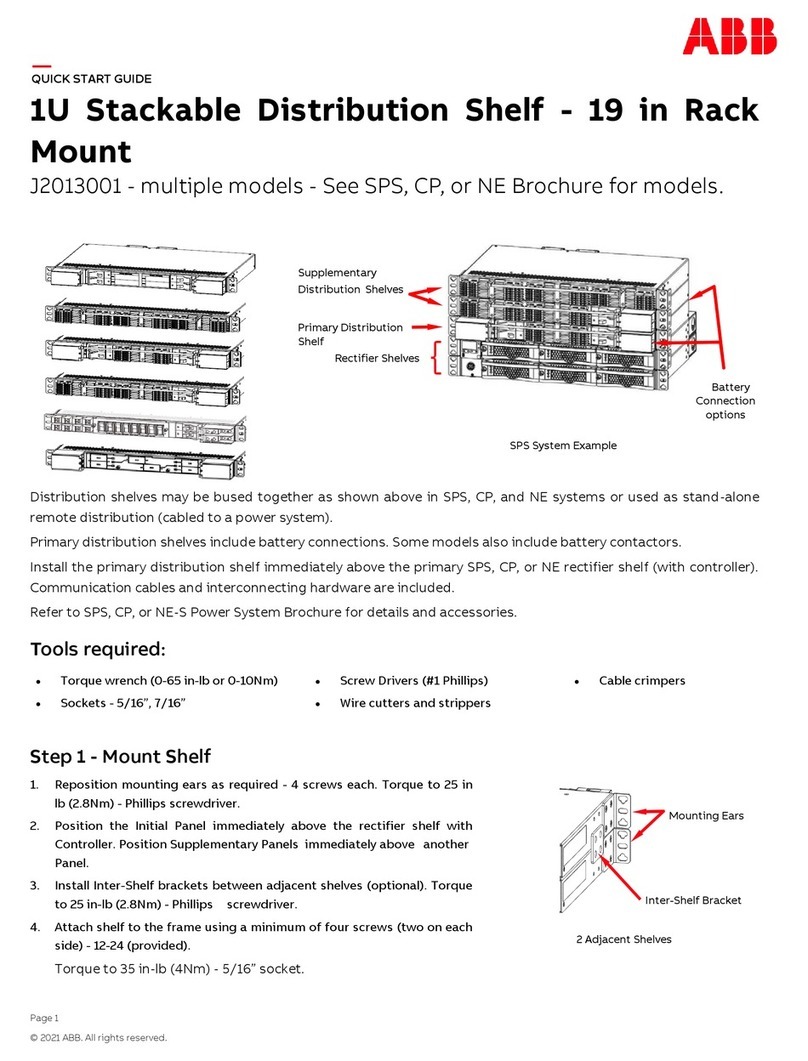
ABB ABILITY SSC600 User manual

—
ABB ABILITY™ SMART SUBSTATION CONTROL AND PROTECTION FOR ELECTRICAL SYSTEMS
SSC600
Operation Manual


Document ID: 1MRS758850
Issued: 2021-11-26
Revision: C
Product version: 1.0 FP3
© Copyright 2021 ABB. All rights reserved

Copyright
This document and parts thereof must not be reproduced or copied without written permission from
ABB, and the contents thereof must not be imparted to a third party, nor used for any unauthorized
purpose.
The software or hardware described in this document is furnished under a license and may be used,
copied, or disclosed only in accordance with the terms of such license.
Trademarks
ABB and Relion are registered trademarks of the ABB Group. All other brand or product names
mentioned in this document may be trademarks or registered trademarks of their respective holders.
SSC600 is an approved Intel® IoT Market Ready Solution.
Open Source Software
This product contains open source software. For license information refer to product documentation at
www.abb.com
.
Warranty
Please inquire about the terms of warranty from your nearest ABB representative.
www.abb.com/mediumvoltage

Disclaimer
The data, examples and diagrams in this manual are included solely for the concept or product
description and are not to be deemed as a statement of guaranteed properties. All persons responsible
for applying the equipment addressed in this manual must satisfy themselves that each intended
application is suitable and acceptable, including that any applicable safety or other operational
requirements are complied with. In particular, any risks in applications where a system failure and/or
product failure would create a risk for harm to property or persons (including but not limited to
personal injuries or death) shall be the sole responsibility of the person or entity applying the
equipment, and those so responsible are hereby requested to ensure that all measures are taken to
exclude or mitigate such risks.
This product has been designed to be connected and communicate data and information via a network
interface which should be connected to a secure network. It is the sole responsibility of the person or
entity responsible for network administration to ensure a secure connection to the network and to take
the necessary measures (such as, but not limited to, installation of firewalls, application of
authentication measures, encryption of data, installation of anti virus programs, etc.) to protect the
product and the network, its system and interface included, against any kind of security breaches,
unauthorized access, interference, intrusion, leakage and/or theft of data or information. ABB is not
liable for any such damages and/or losses.
This document has been carefully checked by ABB but deviations cannot be completely ruled out. In
case any errors are detected, the reader is kindly requested to notify the manufacturer. Other than
under explicit contractual commitments, in no event shall ABB be responsible or liable for any loss or
damage resulting from the use of this manual or the application of the equipment.
In case of discrepancies between the English and any other language version, the wording of the
English version shall prevail.

Conformity
This product complies with the directive of the Council of the European Communities on the
approximation of the laws of the Member States relating to electromagnetic compatibility (EMC
Directive 2014/30/EU) and concerning electrical equipment for use within specified voltage limits (Low
Voltage Directive 2014/35/EU). This conformity is the result of tests conducted by ABB in accordance
with the product standard EN 60255-26 for the EMC directive, and with the product standards EN
60255-1 and EN 60255-27 for the low voltage directive. The product is designed in accordance with the
international standards of the IEC 60255 series and IEC 61805-3:2013.

Contents
1 Introduction............................................................................................... 9
1.1 Communication....................................................................................................................................... 9
1.1.1 Ethernet redundancy..............................................................................................................9
1.1.2 Process bus............................................................................................................................. 11
1.2 PCM600 tool........................................................................................................................................... 11
1.2.1 Connectivity packages......................................................................................................... 12
1.2.2 PCM600 and IED connectivity package version.............................................................. 12
1.3 This manual.............................................................................................................................................12
1.3.1 Intended audience.................................................................................................................12
1.4 Document revision history.................................................................................................................. 22
1.5 Related documentation........................................................................................................................22
1.6 Product documentation set................................................................................................................ 22
2 Safety information.................................................................................. 23
3 Commissioning........................................................................................24
3.1 Commissioning checklist.................................................................................................................... 24
3.2 Checking the installation.....................................................................................................................24
3.2.1 Checking of the power supply............................................................................................24
3.3 Authorizations....................................................................................................................................... 24
3.3.1 User authorization................................................................................................................ 25
3.4 Setting IED and communication........................................................................................................ 26
3.4.1 Setting the communication between IEDs and PCM600..............................................26
3.4.2 Communication settings.....................................................................................................26
3.5 Testing the IED operation....................................................................................................................27
3.5.1 Selecting the IED test mode................................................................................................27
3.5.2 Testing functions.................................................................................................................. 27
3.5.3 Selecting the internal fault test..........................................................................................28
3.5.4 Selecting the IED blocked or IED test and blocked mode.............................................28
3.6 ABB Product Data Registration.......................................................................................................... 29
4 IED operation........................................................................................... 30
4.1 Web HMI..................................................................................................................................................30
4.1.1 Authorization......................................................................................................................... 30
4.1.2 Using the Web HMI................................................................................................................ 31
4.1.3 Identifying the device...........................................................................................................35
4.1.4 Showing parameters............................................................................................................ 35
4.1.5 Editing values.........................................................................................................................36
Contents
SSC600
Operation Manual
7
4.1.6 Committing settings............................................................................................................38
4.1.7 Clearing and acknowledging.............................................................................................. 38
4.1.8 Web HMI views.......................................................................................................................39
4.2 Disturbance identification.................................................................................................................. 46
4.3 IED parametrization............................................................................................................................. 46
4.3.1 Settings for IED functionality............................................................................................. 47
4.3.2 Settings for different operating conditions....................................................................47
4.3.3 Activating programmable virtual LEDs.............................................................................47
4.4 Monitoring..............................................................................................................................................48
4.4.1 Indications..............................................................................................................................48
4.4.2 Recorded data....................................................................................................................... 48
4.4.3 Monitoring fault records..................................................................................................... 50
4.4.4 Monitoring events.................................................................................................................50
4.4.5 Remote monitoring.............................................................................................................. 50
4.5 Controlling.............................................................................................................................................. 51
4.5.1 Controlling with single-line diagram................................................................................. 51
5 Troubleshooting...................................................................................... 57
5.1 Identifying hardware errors................................................................................................................ 57
5.2 Identifying runtime errors................................................................................................................... 57
5.3 Identifying communication errors.....................................................................................................57
5.3.1 Internal faults.........................................................................................................................57
5.3.2 Warnings.................................................................................................................................58
5.4 Correction procedures.........................................................................................................................60
5.4.1 Rebooting the software...................................................................................................... 60
5.4.2 Restoring factory settings..................................................................................................60
5.4.3 Setting passwords............................................................................................................... 60
5.4.4 Identifying IED application problems............................................................................... 61
6 Environmental aspects........................................................................... 62
6.1 Sustainable development....................................................................................................................62
6.2 Disposal of an IED................................................................................................................................. 62
7 Glossary.................................................................................................... 63
Contents
8 SSC600
Operation Manual

1 Introduction
ABB Ability™ Smart Substation Control and Protection for electrical systems
SSC600 is a Smart Substation device designed for protection, control,
measurement and supervision of utility substations and industrial switchgear and
equipment. The design of the device has been guided by the IEC 61850 standard for
communication and interoperability of substation automation devices. It is fully
integrable with Relion series IEDs for creating a complete solution. Optional
functionality is available at the time of order for both software and hardware, for
example, special application packages and additional communication modules.
Figure 1: SSC600
1.1 Communication
The IED supports the IEC 61850 standard and its specified GOOSE, MMS and
SAV/SMV communication profiles. Operational information and controls are
available through these protocols.
The IEC 61850 communication implementation supports all monitoring and control
functions. Additionally, parameter settings, disturbance recordings and fault
records can be accessed using the IEC 61850 protocol. Disturbance recordings are
available to any Ethernet-based application in the IEC 60255-24 standard
COMTRADE file format. The IED can receive binary signals from other devices (so-
called horizontal communication) using the IEC 61850-8-1 GOOSE profile, where the
highest performance class with a total transmission time of 3 ms is supported.
Furthermore, the IED supports receiving of analog values using GOOSE messaging.
The IED meets the GOOSE performance requirements for class P1 (10 ms) tripping
applications in distribution substations, as defined by the IEC 61850 standard.
The IED can support five simultaneous clients for IEC 61850 MMS reporting. The IED
supports receiving sampled analogue measurements according to IEC 61850-9-2LE
from up to 30 Merging Units or other IEDs.
1MRS758850 C Introduction
SSC600
Operation Manual
9

1.1.1 Ethernet redundancy
IEC 61850 specifies a network redundancy scheme that improves the system
availability for substation communication. It is based on parallel redundancy
protocol PRP-1 defined in the IEC 62439-3:2012 standard. The protocol relies on the
duplication of all transmitted information via two Ethernet ports for one logical
network connection. Therefore, it is able to overcome the failure of a link or switch
with a zero-switchover time, thus fulfilling the stringent real-time requirements for
the substation automation horizontal communication and time synchronization.
PRP specifies that each device is connected in parallel to two local area networks.
Thus, each device incorporates a switch element that forwards frames from port to
port.
IEC 62439-3:2012 cancels and replaces the first edition published in 2010.
These standard versions are also referred to as IEC 62439-3 Edition 1 and
IEC 62439-3 Edition 2. The IED supports IEC 62439-3:2012 and it is not
compatible with IEC 62439-3:2010.
PRP
Each PRP node, called a doubly attached node with PRP (DAN), is attached to two
independent LANs operated in parallel. These parallel networks in PRP are called
LAN A and LAN B. The networks are completely separated to ensure failure
independence, and they can have different topologies. Both networks operate in
parallel, thus providing zero-time recovery and continuous checking of redundancy
to avoid communication failures. Non-PRP nodes, called single attached nodes
(SANs), are either attached to one network only (and can therefore communicate
only with DANs and SANs attached to the same network), or are attached through a
redundancy box, a device that behaves like a DAN.
Figure 2: PRP solution
Introduction 1MRS758850 C
10 SSC600
Operation Manual

In case a laptop or a PC workstation is connected as a non-PRP node to one of the
PRP networks, LAN A or LAN B, it is recommended to use a redundancy box device
or an Ethernet switch with similar functionality between the PRP network and SAN
to remove additional PRP information from the Ethernet frames. In some cases,
default PC workstation adapters are not able to handle the maximum-length
Ethernet frames with the PRP trailer.
There are different alternative ways to connect a laptop or a workstation as SAN to
a PRP network.
• Via an external redundancy box (RedBox) or a switch capable of connecting to
PRP and normal networks
• By connecting the node directly to LAN A or LAN B as SAN
1.1.2 Process bus
Process bus IEC 61850-9-2 defines the transmission of Sampled Measured Values
within the substation automation system. UCA users' group created a guideline IEC
61850-9-2 LE that defines an application profile of IEC 61850-9-2 to facilitate
implementation and enable interoperability. Process bus is used for distributing
process data from the primary circuit to all process bus compatible IEDs in the local
network in a real-time manner. The data can then be processed by any IED to
perform different protection, automation and control functions.
Transmitting measurement samples over process bus brings also higher error
detection because the signal transmission is automatically supervised. Additional
contribution to the higher availability is the possibility to use redundant Ethernet
network for transmitting SMV signals.
The SSC600 supports receiving of sampled values of analog currents and voltages.
The measured values need to be transferred as sampled values using the IEC
61850-9-2 LE protocol.
The SSC600 IEDs with process bus based applications use IEEE 1588 v2 Precision
Time Protocol (PTP) according to IEEE C37.238-2011 Power Profile for high accuracy
time synchronization. With IEEE 1588 v2, the cabling infrastructure requirement is
reduced by allowing time synchronization information to be transported over the
same Ethernet network as the data communications.
When using PTP in redundant mode, synchronization master is primarily
searched from LAN A. Synchronization master from LAN B is used only, if
no master in LAN A is detected.
1.2 PCM600 tool
Protection and Control IED Manager PCM600 offers all the necessary functionality
to work throughout all stages of the IED life cycle.
• Planning
• Engineering
• Commissioning
• Operation and disturbance handling
• Functional analysis
1MRS758850 C Introduction
SSC600
Operation Manual
11

The whole substation can be controlled and different tasks and functions can be
performed with the individual tool components. PCM600 can operate with many
different topologies, depending on the customer needs.
For more information, refer to PCM600 documentation.
1.2.1 Connectivity packages
A connectivity package is a software component that consists of executable code
and data which enables system tools to communicate with an IED. Connectivity
packages are used to create configuration structures in PCM600. The latest
PCM600 and connectivity packages are backward compatible with older IED
versions.
A connectivity package includes all of the data which is used to describe the IED. For
example, it contains a list of the existing parameters, data format used, units,
setting range, access rights and visibility of the parameter. In addition, it contains
code which allows software packages that consume the connectivity package to
properly communicate with the IED. It also allows for localization of text even when
its read from the IED in a standard format such as COMTRADE.
Update Manager is a tool that helps in defining the right connectivity package
versions for different system products and tools. Update Manager is included with
products that use connectivity packages.
1.2.2 PCM600 and IED connectivity package version
• Protection and Control IED Manager PCM600 2.9 or later
• SSC600 Connectivity Package Ver.1.0 or later
Download connectivity packages from the ABB Web site
www.abb.com/
mediumvoltage
or directly with the Update Manager in PCM600.
1.3 This manual
The operation manual contains instructions on how to operate the IED once it has
been commissioned. The manual provides instructions for monitoring, controlling
and setting the IED. The manual also describes how to identify disturbances and
how to view calculated and measured power grid data to determine the cause of a
fault.
1.3.1 Intended audience
This manual addresses the operator, who operates the IED on a daily basis.
The operator must be trained in and have a basic knowledge of how to operate
protection equipment. The manual contains terms and expressions commonly used
to describe this kind of equipment.
Introduction 1MRS758850 C
12 SSC600
Operation Manual

1.3.1.1 Document conventions
A particular convention may not be used in this manual.
• Abbreviations and acronyms in this manual are spelled out in the glossary. The
glossary also contains definitions of important terms.
• whmi menu paths are presented in bold typeface.
Select Main menu > Settings.
• whmi menu names are presented in bold typeface.
Click Information in the whmi menu structure.
• Parameter names are shown in
italics
.
The function can be enabled and disabled with the
Operation
setting.
• Parameter values are indicated with quotation marks.
The corresponding parameter values are "On" and "Off".
• ied input/output messages and monitored data names are shown in Courier
font.
When the function starts, the START output is set to TRUE.
1.3.1.2 Symbols
The warning icon indicates the presence of a hazard which could result in
electrical shock or other personal injury.
The caution icon indicates important information or warning related to
the concept discussed in the text. It might indicate the presence of a
hazard which could result in corruption of software or damage to
equipment or property.
The information icon alerts the reader of important facts and conditions.
The tip icon indicates advice on, for example, how to design your project
or how to use a certain function.
Although the warning hazards are related to personal injury, it is necessary to
understand that under certain operational conditions, operation of damaged
equipment may result in degraded process performance leading to personal injury
or death. Therefore, comply fully with all warning and caution notices.
1.3.1.3 Functions, codes and symbols
All available functions included in the IED are listed in the tables below. Available
functions depend on the chosen product options.
1MRS758850 C Introduction
SSC600
Operation Manual
13

Table 1: Protection functions
Function IEC 61850 IEC 60617 ANSI Logical
device
Logical
nodes
Three-phase
non-direc-
tional over-
current pro-
tection, low
stage
PHLPTOC 3I> 51P-1 LD0 PHLPTOC
Three-phase
non-direc-
tional over-
current pro-
tection, high
stage
PHHPTOC 3I>> 51P-2 LD0 PHHPTOC
Three-phase
non-direc-
tional over-
current pro-
tection, in-
stantaneous
stage
PHIPTOC 3I>>> 50P LD0 PHIPTOC
Three-phase
directional
overcurrent
protection,
low stage
DPHLPDOC 3I> -> 67P/51P-1 LD0 DPHLPTOC
DPHLRDIR
Three-phase
directional
overcurrent
protection,
high stage
DPHHPDOC 3I>> -> 67P/51P-2 LD0 DPHHPTOC
DPHHRDIR
Non-direc-
tional earth-
fault protec-
tion, low
stage
EFLPTOC Io> 51G/51N-1 LD0 EFLPTOC
Non-direc-
tional earth-
fault protec-
tion, high
stage
EFHPTOC Io>> 51G/51N-2 LD0 EFHPTOC
Non-direc-
tional earth-
fault protec-
tion, instanta-
neous stage
EFIPTOC Io>>> 50G/50N LD0 EFIPTOC
Directional
earth-fault
protection,
low stage
DEFLPDEF Io> -> 67G/N-1
51G/N-1
LD0 DEFLPTOC
DEFLRDIR
Directional
earth-fault
protection,
high stage
DEFHPDEF lo>> -> 67G/N-1
51G/N-2
LD0 DEFHPTOC
DEFHRDIR
Table continues on the next page
Introduction 1MRS758850 C
14 SSC600
Operation Manual

Function IEC 61850 IEC 60617 ANSI Logical
device
Logical
nodes
Admittance-
based earth-
fault protec-
tion
EFPADM Yo> -> 21YN LD0 EFPADM
Wattmetric-
based earth-
fault protec-
tion
WPWDE Po> -> 32N LD0 WRDIR
WPSDE
WMMXU
Transient/
intermittent
earth-fault
protection
INTRPTEF lo> -> IEF 67NTEF/NIEF LD0 INTRPTEF
Non-direc-
tional (cross-
country)
earth-fault
protection,
using calcula-
ted Io
EFHPTOC Io>> 51G/51N-2 LD0 EFHPTOC
Negative-se-
quence over-
current pro-
tection
NSPTOC I2> 46M LD0 NSPTOC
Phase discon-
tinuity pro-
tection
PDNSPTOC I2/I1> 46PD LD0 PDNSPTOC
Residual over-
voltage pro-
tection
ROVPTOV Uo> 59G/59N LD0 ROVPTOV
Three-phase
undervoltage
protection
PHPTUV 3U< 27 LD0 PHPTUV
Three-phase
overvoltage
protection
PHPTOV 3U> 59 LD0 PHPTOV
Positive-se-
quence un-
dervoltage
protection
PSPTUV U1< 27PS LD0 PSPTUV
Negative-se-
quence over-
voltage pro-
tection
NSPTOV U2> 59NS LD0 NSPTOV
Frequency
protection
FRPFRQ f>/f<,df/dt 81 LD0 FRPTRC
FRPTOF
FRPTUF
FRPFRC
Table continues on the next page
1MRS758850 C Introduction
SSC600
Operation Manual
15

Function IEC 61850 IEC 60617 ANSI Logical
device
Logical
nodes
Distance pro-
tection
DSTPDIS Z< 21P, 21N LD0 GFCPDIS
GFCRDIR
DST1PDIS
DST2PDIS
DST3PDIS
DST4PDIS
DST5PDIS
DSTRDIR
GFC1RFRC
GFC2RFRC
GFC3RFRC
Three-phase
thermal pro-
tection for
feeders, ca-
bles and dis-
tribution
transformers
T1PTTR 3Ith>F 49F LD0 T1PTTR
Three-phase
thermal over-
load protec-
tion, two time
constants
T2PTTR 3Ith>T/G/C 49T/G/C LD0 T2PTTR
Negative-se-
quence over-
current pro-
tection for
ma- chines
MNSPTOC I2>M 46M LD0 MNSPTOC
Loss of load
supervision
LOFLPTUC 3I< 37 LD0 LOFLPTUC
Motor load
jam protec-
tion
JAMPTOC Ist> 50TDJAM LD0 JAMPTOC
Motor start-
up supervi-
sion
STTPMSU Is2t n< 49,66,48,50T
DLR
LD0 STTPMSS
STTPMRI
Phase rever-
sal protection
PREVPTOC I2>> 46R LD0 PREVPTOC
Thermal over-
load protec-
tion for mo-
tors
MPTTR 3Ith>M 49M LD0 MPTTR
Table continues on the next page
Introduction 1MRS758850 C
16 SSC600
Operation Manual

Function IEC 61850 IEC 60617 ANSI Logical
device
Logical
nodes
Stabilized and
instantane-
ous differen-
tial protec-
tion for two-
winding
transformers
TR2PTDF 3dI>T 87T LD0 TR2PTRC
TR2LPDIF
TR2H2PHAR
TR2H5PHAR
TR2HPDIF
Numerically
stabilized
low-impe-
dance restric-
ted earth-
fault protec-
tion
LREFPNDF dIoLo> 87NLI LD0 LREFPDIF
LREFPHAR
Circuit break-
er failure pro-
tection
CCBRBRF 3I>/Io>BF 50BF LD0 CCBRBRF
Three-phase
inrush detec-
tor
INRPHAR 3I2f> 68HB LD0 INRPHAR
Switch onto
fault
CBPSOF SOTF SOTF LD0 CBPSOF
Master trip TRPPTRC Master Trip 94/86 LD0 TRPPTRC
Arc protec-
tion
ARCSARC ARC AFD LD0 ARCSARC
ARC1PIOC
ARC2PIOC
ARCPTRC
Multipurpose
protection
MAPGAPC MAP MAP LD0 MAPGAPC
Load-shed-
ding and re-
storation
LSHDPFRQ UFLS/R 81LSH LD0 LSHDPTRC
LSHDPTOF
LSHDPTUF
LSHDPFRC
Fault locator SCEFRFLO FLOC FLOC LD0 SCEFRFLO
SCEFZLIN
SCEF2ZLIN
SCEF3ZLIN
FLORFRC
Reverse pow-
er/directional
overpower
protection
DOPPDPR P>/Q> 32R/32O LD0 DPPDOP
DOPMMXU
Three-phase
underimpe-
dance protec-
tion
UZPDIS Z>G 21G LD0 UZPDIS
UZMMXU
Multifrequen-
cy admit-
tance-based
earth-fault
protection
MFADPSDE Io> ->Y 67NYH LD0 MFADPSDE
MFADRDIR
Table continues on the next page
1MRS758850 C Introduction
SSC600
Operation Manual
17

Function IEC 61850 IEC 60617 ANSI Logical
device
Logical
nodes
Busbar differ-
ential protec-
tion
BBPBDF 3Id/I 87BL LD0 BBPTRC
ZNAPDIF
ZNBPDIF
ZNCZPDIF
SFAPDIF
SFBPDIF
BBCCSPVC
Busbar zone
selection
ZNRSRC ZNRSRC ZNRSRC LD0 ZNRSRC
Load blinder LBRDOB LB 21LB LD0 LBRDOB
LBMMXU
Table 2: Interconnection functions
Function IEC 61850 IEC 60617 ANSI Logical
device
Logical
nodes
Directional re-
active power
undervoltage
protection
DQPTUV Q> ->,3U< 32Q,27 LD0 DQPTUV
DQPDOP
DQMMXU
Low-voltage
ride-through
protection
LVRTPTUV U<RT 27RT LD0 LVRTPTUV
Table 3: Power quality functions
Function IEC 61850 IEC 60617 ANSI Logical
device
Logical
nodes
Current total
demand dis-
tortion
CMHAI PQM3I PQM3I CMHAI CMHAI
Voltage total
harmonic dis-
tortion
VMHAI PQM3U PQM3V VMHAI VMHAIVMHAI
Voltage varia-
tion
PHQVVR PQMU PQMV PHQVVR
PH2QVVR
PH3QVVR
QVVRQRC
QVV2RQRC
QVV3RQRC
PHQVVR
PH2QVVR
PH3QVVR
QVVMSTA
QVV2MSTA
QVV3MSTA
Voltage un-
balance
VSQVUB PQUUB PQVUB - -
Introduction 1MRS758850 C
18 SSC600
Operation Manual

Table 4: Control functions
Function IEC 61850 IEC 60617 ANSI Logical
device
Logical
nodes
Circuit-break-
er control
CBXCBR I <-> O CB I <-> O CB CTRL CBCSWI
CBCILO
CBXCBR
Disconnector
control
DCXSWI I <-> O DCC I <-> O DCC CTRL DCCSWI
DCCILO
DCXSWI
Earthing
switch con-
trol
ESXSWI I <-> O ESC I <-> O ESC CTRL ESCSWI
ESCILO
ESXSWI
Disconnector
position indi-
cation
DCSXSWI I <-> O DC I <-> O DC CTRL DCSXSWI
Earthing
switch indica-
tion
ESSXSWI I <-> O ES I <-> O ES CTRL ESSXSWI
Emergency
start-up
ESMGAPC ESTART ESTART LD0 ESMGAPC
Autoreclosing DARREC O -> I 79 LD0 DARREC
Tap changer
position indi-
cation
TPOSYLTC TPOSM 84M LD0 TPOSYLTC
Tap changer
control with
voltage regu-
lator
OLATCC COLTC 90V LD0 OLATCC
Synchronism
and energiz-
ing check
SECRSYN SYNC 25 LD0 SECRSYN
Table 5: Condition monitoring and supervision functions
Function IEC 61850 IEC 60617 ANSI Logical
device
Logical
nodes
Circuit-break-
er condition
monitoring
SSCBR CBCM CBCM LD0 SSCBR1
SPH1SCBR
SPH2SCBR
SPH3SCBR
SSOPM
SSIMG
Runtime
counter for
machines and
devices
MDSOPT OPTS OPTM LD0 MDSOPT
1MRS758850 C Introduction
SSC600
Operation Manual
19

Table 6: Measurement functions
Function IEC 61850 IEC 60617 ANSI Logical
device
Logical
nodes
Disturbance
recorder
RDRE DR DFR LD0 DR_LLN0
DR_LPHD
RDRE
RBDR
Fault record FLTRFRC FAULTREC FAULTREC LD0 FLTRFRC
Three-phase
current meas-
urement
CMMXU 3I 3I LD0 CMMXU
CAVMMXU
CMAMMXU
CMIMMXU
Sequence cur-
rent measure-
ment
CSMSQI I1, I2, I0 I1, I2, I0 LD0 CSMSQI
Residual cur-
rent measure-
ment
RESCMMXU Io In LD0 RESCMMXU
RCAVMMXU
RCMAMMXU
RCMIMMXU
Three-phase
voltage meas-
urement
VMMXU 3U 3V LD0 VMMXU
VAVMMXU
Residual volt-
age measure-
ment
RESVMMXU Uo Vn LD0 RESVMMXU
RVAVMMXU
RVMAMMXU
RVMIMMXU
Sequence
voltage meas-
urement
VSMSQI U1, U2, U0 V1, V2, V0 LD0 VSMSQI
Three-phase
power and
energy meas-
urement
PEMMXU P, E P, E LD0 PEMMXU
PEMMTR
PEAVMMXU
PEMAMMXU
PEMIMMXU
Table continues on the next page
Introduction 1MRS758850 C
20 SSC600
Operation Manual
Other manuals for ABILITY SSC600
3
Table of contents
Other ABB Network Hardware manuals

ABB
ABB MicroSCADA Pro SYS 600 Parts list manual

ABB
ABB M4M 30 User manual

ABB
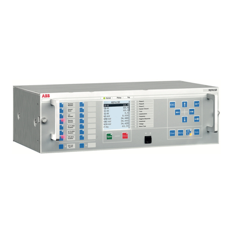
ABB RELION REF615R User manual

ABB
ABB RobotWare 6.02 Instructions for use

ABB
ABB iPAQ User manual

ABB
ABB J2013001 User manual

ABB
ABB M1M 10 User manual

ABB
ABB i-bus KNX IPR/S 3.5.1 User manual

ABB
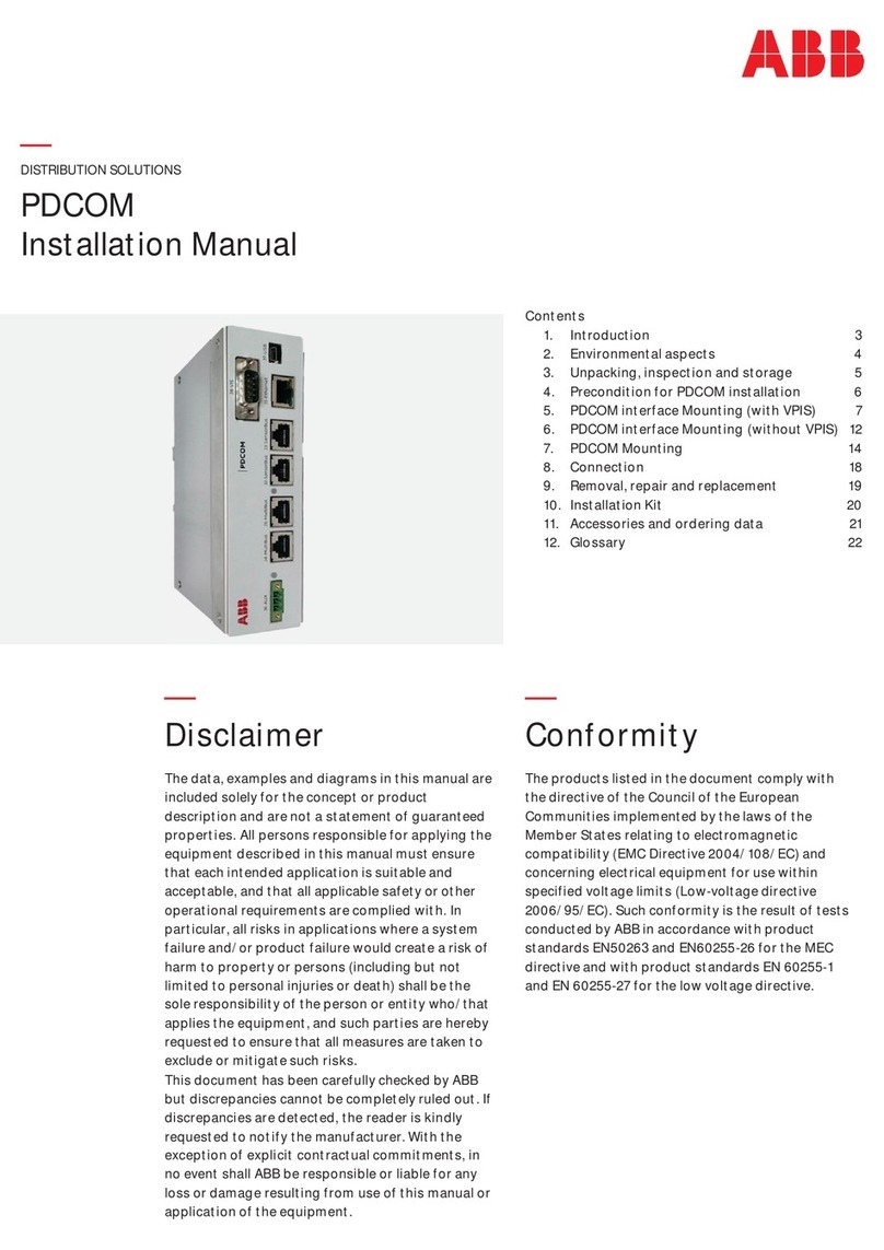
ABB PDCOM User manual

ABB
ABB AWIN GW100 User manual