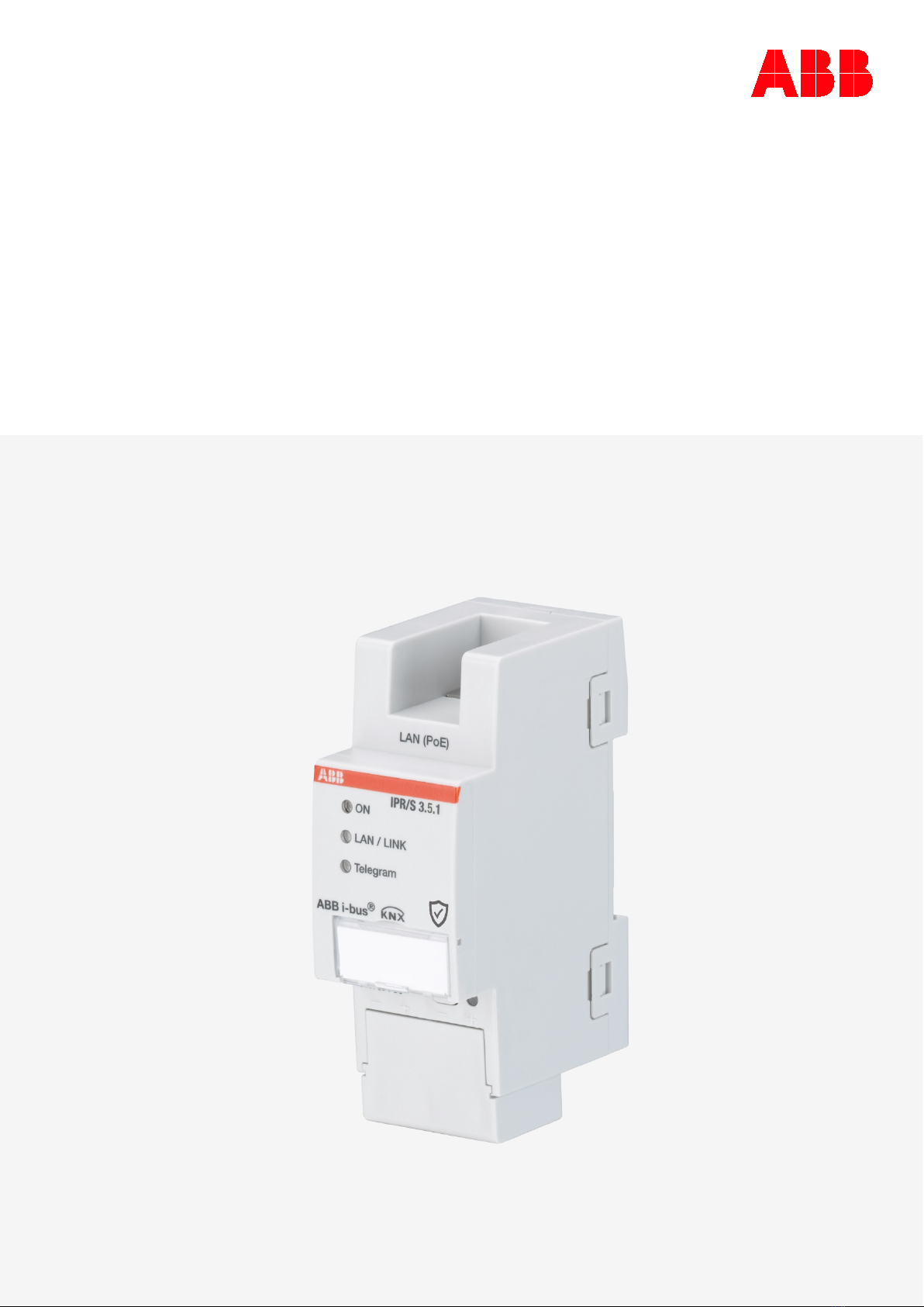
ABB i-bus KNX IPR/S 3.5.1 User manual

—
PRODUCT MANUAL
ABB i-bus®KNX
IPR/S 3.5.1
IP Router Secure


ABB i-bus®KNX
Contents
IPR/S 3.5.1 | 2CDC502099D0211 Rev. A iii
Contents
Page
1General ................................................................................................. 5
1.1 Using the product manual............................................................................................................ 5
1.1.1 Notes ........................................................................................................................................... 5
1.2 Cyber security (network security) ................................................................................................ 6
1.3 Preventing access to the different media..................................................................................... 6
1.4 Twisted pair cabling..................................................................................................................... 6
1.5 IP cabling inside the building ....................................................................................................... 6
1.6 Connection to the Internet ........................................................................................................... 7
1.7 KNXnet/IP Security...................................................................................................................... 7
1.8 Overview of product and functions .............................................................................................. 7
1.8.1 Monitoring for bus voltage failure................................................................................................. 8
1.8.2 Overview of versions ................................................................................................................... 9
2Device technology ............................................................................. 11
2.1 Technical data ............................................................................................................................11
2.2 Connection diagram ...................................................................................................................13
2.3 Dimension drawing .....................................................................................................................14
2.4 Mounting and installation............................................................................................................15
2.4.1 Prerequisites for commissioning.................................................................................................15
2.4.2 Supplied state.............................................................................................................................15
2.4.3 Assignment of the physical address ...........................................................................................16
2.4.4 Download reaction......................................................................................................................16
2.4.5 Unloading the device and resetting to factory settings ...............................................................16
2.4.6 Cleaning .....................................................................................................................................17
2.4.7 Maintenance ...............................................................................................................................17
2.5 Description of inputs and outputs ...............................................................................................17
2.6 Operating controls ......................................................................................................................18
2.7 Display elements ........................................................................................................................18
3Commissioning.................................................................................. 19
3.1 Overview.....................................................................................................................................19
3.2 Parameters .................................................................................................................................19
3.2.1 Parameter window KNX -> LAN .................................................................................................20
3.2.2 Parameter window LAN -> KNX .................................................................................................23
3.2.3 Parameter window IP settings ....................................................................................................26
3.3 Group objects .............................................................................................................................30
3.4 Use of the integrated tunneling servers......................................................................................31
3.4.1 Settings in ETS 5........................................................................................................................32
3.5 KNX Secure................................................................................................................................33
4Planning and application .................................................................. 35
4.1 The IP Router Secure in the network..........................................................................................35
4.1.1 Assignment of IP address...........................................................................................................35
4.1.2 KNX telegrams in the network ....................................................................................................36
4.1.3 Monitoring an IPR/S 3.5.1...........................................................................................................37
4.1.4 System broadcast.......................................................................................................................37
4.1.5 IGMP ..........................................................................................................................................38
4.1.6 IPR/S as an area coupler............................................................................................................38
4.1.7 IPR/S as a line coupler ...............................................................................................................39
4.1.8 Mixed topology ...........................................................................................................................40
4.2 The i-bus®Tool...........................................................................................................................41
4.2.1 Discovery....................................................................................................................................41
4.2.2 Firmware update.........................................................................................................................42
AAppendix ............................................................................................ 43
A.1 Ordering details ..........................................................................................................................43
A.2 Open source software components ............................................................................................43

ABB i-bus®KNX
Contents
vi 2CDC502099D0211 Rev. A | IPR/S 3.5.1

ABB i-bus®KNX
General
IPR/S 3.5.1 | 2CDC502099D0211 Rev. A 5
1 General
The ABB i-bus®IP Router Secure IPR/S 3.5.1 connects the KNX bus with an Ethernet network. KNX
telegrams can be sent to or received from other devices via the network.
The device supports the KNX Secure protocol (KNXnet/IP Security).
1.1 Using the product manual
This manual provides detailed technical information on the function, installation and programming of the
ABB i-bus®KNX device. Explanations on how to use it are accompanied by examples.
This manual is divided into the following chapters:
Chapter 1 General
Chapter 2 Device technology
Chapter 3 Commissioning
Chapter 4 Planning and application
Chapter A Appendix
1.1.1 Notes
Notes and safety instructions are represented as follows in this manual:
Note
Tips on usage and operation
Examples
Application examples, installation examples, programming examples
Important
These safety instructions are used if there is danger of a malfunction without risk of damage or injury.
Caution
These safety instructions are used if there is danger of a malfunction without risk of damage or injury.
Danger
These safety instructions are used if there is a danger to life and limb with inappropriate use.
Danger
These safety instructions are used if there is an extreme danger to life with inappropriate use.

ABB i-bus®KNX
General
62CDC502099D0211 Rev. A | IPR/S 3.5.1
1.2 Cyber security (network security)
The industry is increasingly faced with cyber security risks. To increase the stability, security and
robustness of its solutions, ABB has introduced official robustness tests for Internet security as part of the
product development process.
In addition, the information below includes guidelines and mechanisms that you can use to improve the
security of KNX systems.
1.3 Preventing access to the different media
The basis for any protection concept is the careful shielding of the system against unauthorized access.
Only authorized persons (installers, janitors and users) should have physical access to a KNX system. The
critical points of every KNX medium must be protected as well as possible during planning and installation.
In general, applications and devices should be permanently installed to prevent their easy removal and in
this way prevent access to the KNX system for unauthorized persons. Subdistributions with KNX devices
should be closed, or in rooms to which only authorized persons have access.
1.4 Twisted pair cabling
►
The ends of KNX twisted pair cables should not be visible or protrude from the wall either inside or
outside the building.
►
If available, use the anti
-theft devices on the application modules.
►
Bus cables outdoors represent an
elevated risk. Ensure that physical access to KNX twisted pair
cables is especially difficult here.
►
For extra security, devices installed in areas with limited protection (outdoor areas, underground
parking lots, restrooms, etc.) can be designed as a se
parate line. Enabling the filter tables in the line
coupler (KNX only) prevents attackers from gaining access to the whole system.
1.5 IP cabling inside the building
For building automation, use a separate LAN or WiFi network with its own hardware (routers, switches,
etc.).
Regardless of the KNX system, apply the usual security mechanisms for IP networks. These are
examples:
•MAC filter
•Encryption of wireless networks
•Usage of strong passwords and protection of these against access by unauthorized persons
Note
The device cannot be reached during IP, TCP or UDP flooding (access from the Internet). To prevent
this reaction, set a data rate limit at network level.
Please discuss the topic with your network administrator.

ABB i-bus®KNX
General
IPR/S 3.5.1 | 2CDC502099D0211 Rev. A 7
1.6 Connection to the Internet
The device is not intended for use on the public Internet. For this reason router ports in the direction of the
Internet must not be opened; this action will ensure KNX communication is not visible on the Internet.
Systems can be accessed via the Internet in the following ways:
•Access to KNX installations via VPN connections. However, this requires a router with VPN server
functionality.
•Use of manufacturer-specific solutions or visualizations, e.g. access via https.
1.7 KNXnet/IP Security
The device should always be operated in KNX Secure mode. This ensures security for runtime
communication on the IP backbone, for the tunneling servers and for commissioning the device itself.
See also chapter 3.5, KNX Secure.
1.8 Overview of product and functions
The ABB i-bus®IP Router Secure IPR/S 3.5.1 connects the KNX bus with an Ethernet network. KNX
telegrams can be sent to or received from other devices via the network.
The device uses the KNXnet/IP protocol and the KNXnet/IP Security protocol from the KNX Association
(routing and tunneling) for communication.

ABB i-bus®KNX
General
82CDC502099D0211 Rev. A | IPR/S 3.5.1
The Router features five tunneling servers, see chapter 3.4, Use of the integrated tunneling servers. They
support both bus monitor mode and group monitor mode.
The tunneling servers can be operated in KNX Secure mode.
Alternatively to KNX standard communication (multicast), up to ten ABB IP Routers IPR/S 3.x.1 can also
communicate with each other via the unicast protocol, see chapter 4.1.2, KNX telegrams in the network.
KNX Secure mode is not available in this case.
The power supply can be implemented via PoE (Power over Ethernet) according to IEEE 802.3af class 1
or via a supply voltage.
The ABB i-bus®Tool is available for the IP Router Secure devices. It allows the Routers to be found in the
network (IP discovery) and the settings to be made for unicast communication (see chapter 4.2, The i-
bus® Tool).
An ETS app (ABB KNX Bus Update) is available for the firmware update. If KNX Secure mode is not
activated for the devices, a firmware update can also be performed with the i-bus®Tool.
During the update process, the KNX bus (TP) must be connected in addition to the IP network (LAN) so
that the KNX parameters can be restored correctly. Otherwise, the update process will fail.
It must be ensured that no voltage failure (KNX or IP) occurs during the update process, otherwise the
device can be destroyed.
The device supports the KNX standard function “Monitoring for bus voltage failure.” This is a network
management function, which is used by visual display systems, for example (see chapter 1.8.1, Monitoring
for bus voltage failure).
1.8.1 Monitoring for bus voltage failure
The IP Router Secure monitors the KNX TP bus for voltage failure. When the status of the bus voltage
changes, a broadcast command of the type “NetworkParameterWrite” is sent on the IP network.
The following values are sent:
•Bus voltage failure: “00063301” (hex)
•Bus voltage recovery: “00063300” (hex)
These telegrams can be evaluated, e.g. by a visual display system.
Type Info Meaning
NetworkParameterWrite 00 06 33 01 TP1 bus voltage failure
NetworkParameterWrite 00 06 33 00 TP1 bus voltage recovery

ABB i-bus®KNX
General
IPR/S 3.5.1 | 2CDC502099D0211 Rev. A 9
1.8.2 Overview of versions
Device
IPR/S 3.1.1
IPR/S 3.5.1
Application
IP Router /2.0
IP Router
Secure/1.0
ETS
ETS 4/5
ETS 5
Properties of
IP Router
Number of tunneling servers
5
5
Number of unicast connections 10 10
Monitoring for bus voltage failure
(see chapter 1.8.1, Monitoring for bus voltage failure)
Filter Group telegrams main group 0...31
IP discovery (i-bus®Tool)
Firmware update with i-bus®Tool *
Firmware update with KNX Bus Update app -
Unicast parameterization (i-bus®Tool)
*
Power over Ethernet
KNX Secure -
* Only if the device is not operated in KNX Secure mode


ABB i-bus®KNX
Device technology
IPR/S 3.5.1 | 2CDC502099D0211 Rev. A 11
2 Device technology
IPR/S 3.5.1
The IP Router Secure 3.5.1 is the interface between KNX installations and IP networks. It can be used as
a line coupler or area coupler and can utilize the local network (LAN) for exchange of telegrams between
lines/areas.
KNX devices can be programmed via the LAN using the ETS (five tunneling servers are available). The
device uses the KNXnet/IP protocol or the KNXnet/IP Security protocol from the KNX Association (routing
and tunneling).
Alternatively, the device can communicate via unicast.
The device is powered by 12 to 30 V DC or PoE (Power over Ethernet) to IEEE 802.3af class 1.
2.1 Technical data
Supply
Supply voltage Us12…30 V DC (+10% / -15%)
or PoE (IEEE 802.3af class 1)
Power loss
Maximum 1.8 W
Current consumption, supply voltage Maximum 120 mA at 12 V
Rated voltage Un12 V DC
KNX current consumption < 10 mA
Connections
KNX Bus connection terminal
Operating voltage Plug-in terminal
LAN
RJ45 socket for 10/100BaseT,
IEEE 802.3 networks, AutoSensing
Operating and display elements Red LED and button Assignment of the physical address
Green “On” LED
Ready indicator
Yellow “LAN/Link” LED
Network connection indicator
Yellow “Telegram” LED
KNX telegram traffic indicator
Degree of protection
IP 20
To EN 60 529
Protection class
II To EN 61 140
Isolation category
Overvoltage category III to EN 60 664-1
Pollution degree 2 to EN 60 664-1
2CDC071007F0017

ABB i-bus®KNX
Device technology
12 2CDC502099D0211 Rev. A | IPR/S 3.5.1
KNX safety extra low voltage
SELV 30 V DC
Temperature range Operation -5 °C…+45 °C
Storage -25 °C…+55 °C
Transport -25 °C…+70 °C
Ambient conditions
Maximum air humidity
95%, no condensation allowed
Atmospheric pressure
Atmosphere up to 2,000 m
Design
Modular installation device (MDRC)
Modular installation device, pro
M
Dimensions 90 x 36 x 63.5 mm (H x W x D)
Mounting width 2x 18 mm modules
Mounting On 35 mm mounting rail To EN 60 715
Mounting position Any
Weight 0.1 kg
Housing, color
Plastic, halogen free, gray
Approvals
KNX to EN 50491 and EN 60 669-2-5
CE marking
In accordance with the EMC and
Low Voltage Directives
Device type
Application
Maximum number of
group objects
Maximum number of
group addresses
Maximum number of
assignments
IPR/S 3.5.1
IP Router Secure/…* 0 0 0
* … = Current version number of the application. Please refer to the software information on our homepage.
Note
ETS 5 and the current version of the device application are required for programming.
If the device is to be operated in KNX Secure mode, the commissioning key (FDSK; see chapter 3.5,
KNX Secure) on the side of the unit will be required as well.
The latest version of the application and corresponding software information are available for download
from www.abb.com/knx.After import into ETS, the application appears in the Catalogs window under
Manufacturers/ABB/System components/Coupler.
The device does not support the locking function of a KNX device in ETS. If you use a BCU code to
inhibit access to all the project devices, it has no effect on this device. Data can still be read and
programmed.
Exception: When KNX Secure mode is activated, the device can no longer be programmed with a
different ETS.

ABB i-bus®KNX
Device technology
IPR/S 3.5.1 | 2CDC502099D0211 Rev. A 13
2.2 Connection diagram
IPR/S 3.5.1
Legend
1
Label carrier
6
Power supply connection U
s
2
Programming LED
7
Telegram LED
3
Programming button
8
LAN/LINK LED
4
KNX connection
9
ON LED
5
Cover cap
10
LAN or LAN/PoE connection
Note
It is also possible to power the Router via the voltage output without choke of an ABB KNX power
supply (type SV/S).
2CDC072009F0015
2CDC072010F0015

ABB i-bus®KNX
Device technology
14 2CDC502099D0211 Rev. A | IPR/S 3.5.1
2.3 Dimension drawing
IPR/S 3.5.1
2CDC072011F0015

ABB i-bus®KNX
Device technology
IPR/S 3.5.1 | 2CDC502099D0211 Rev. A 15
2.4 Mounting and installation
The device is a modular DIN rail component for quick installation in distribution boards on 35 mm mounting
rails to EN 60 715.
The mounting position for the device can be selected as required.
The connection to the bus is implemented using the bus connection terminal supplied. The terminal
assignment is located on the housing.
The device is ready for operation after connection of the bus voltage and the supply voltage.
The device must be accessible for operation, testing, visual inspection, maintenance and repair in
compliance with DIN VDE 0100-520.
2.4.1 Prerequisites for commissioning
A PC with the latest version of ETS 5 and a supply voltage of 12 to 30 V DC are required in order to
commission the device. Alternatively, the device can be powered via PoE (Power over Ethernet) to IEEE
802.3af class 1.
The device is ready for operation after connection to the bus voltage and supply voltage.
Mounting and commissioning are only allowed to be carried out by electricians. The standards, directives,
regulations and specifications applicable in the related country must be observed during the planning and
setting up of electrical installations and security systems for intrusion and fire detection.
•Protect the device against damp, dirt and damage during transport, storage and operation!
•Only operate the device within the specified technical data!
•The device should only be operated in an enclosed housing (distribution board)!
•Disconnect the device from the supply of electrical power before mounting.
Danger
To avoid dangerous touch voltages which originate through feedback from differing phase conductors,
all poles must be disconnected when extending or modifying the electrical connections.
2.4.2 Supplied state
The device is supplied with the physical address 15.15.0.
All physical tunneling connection addresses are set to 15.15.100 in the supplied state. In other words, only
one tunnel is visible to the outside. The tunneling connection addresses set in the ETS will be adopted
only after the first download.
The IP address is set to automatic IP assignment (DHCP/AutoIP).
Note
The device is supplied with the option Route. This is not the default setting in the application, but it
simplifies commissioning. See chapter 3.2.1, Parameter window KNX -> LAN.
The programmed setting will be adopted after the first download.

ABB i-bus®KNX
Device technology
16 2CDC502099D0211 Rev. A | IPR/S 3.5.1
2.4.3 Assignment of the physical address
The physical addresses and parameters are assigned and programmed in the ETS.
The device features a Programming button for physical address assignment. The red Programming LED
lights up after the button has been pressed. It goes off as soon as ETS has assigned the physical address
or the Programming button is pressed again.
2.4.4 Download reaction
The device can be programmed in various ways: via one of the integrated tunneling servers, via local
download, via KNXnet/IP routing or via another programming interface (USB or IP).
Note
Any USB interface used for programming a KNX Secure device must support “long frames.” One
suitable USB interface is the USB/S 1.2 from ABB.
There must be a connection to the KNX TP (twisted pair) in order to program the device.
After the download is complete, the device reboots and closes all open tunneling connections. If the
device’s IP address was changed during the download, the tunneling connections must be reconfigured
manually in the tunneling clients. Tunneling clients establish the connection to the server via the
IP address.
The data programmed with the ETS is adopted approx. 30-60 seconds after the download.
2.4.5 Unloading the device and resetting to factory settings
The device can be reset to the factory settings. This is a secure device, so the following information must
be observed:
When the device is operated in KNX Secure mode, it can be reset via the ETS only if the ETS uses the
project with which the device was parameterized or if the commissioning key is available in the project.
The device can be unloaded by right-clicking it in the ETS.
Option: Unloading the application
•The IP address and IP configuration will be retained
•Any unicast configuration will be retained
•The passwords and IP addresses of the tunneling servers will be deleted
•The key for multicast communication (“backbone key”) will be retained
•The tool key assigned by the ETS will be retained. In other words, the FDSK will not be needed for
reprogramming
•The physical address will be retained
Option: Unloading the physical address and the application
•The device will be reset to the factory state
•The FDSK will be needed for re-commissioning unless it is still available in the ETS project from the
original commissioning process

ABB i-bus®KNX
Device technology
IPR/S 3.5.1 | 2CDC502099D0211 Rev. A 17
The reset to factory settings can also be performed directly on the device. This is not a security risk,
because the device will no longer be part of the system afterward.
•Press the Programming button when the KNX bus is not connected
•Hold the Programming button down and plug on the bus terminal. The Programming LED flashes (2
Hz)
•Press the button, hold it for at least 5 s and then release it. The Programming LED goes out, and the
device reboots with the factory settings
The Router can be reprogrammed if the ETS connects with the device after reset and if the device’s FDSK
key is still known to the ETS. The ETS will report that the device was reset in this case.
See chapter 3.5, KNX Secure, for more information about the FDSK (Factory Default Setup Key).
.
2.4.6 Cleaning
Disconnect the device from the supply of electrical power before cleaning. If devices become dirty, they
can be cleaned using a dry cloth or a cloth dampened with a soapy solution. Corrosive agents or solutions
must never be used.
2.4.7 Maintenance
The device is maintenance-free. In the event of damage, e.g. during transport and/or storage, repairs are
not allowed to be made.
2.5 Description of inputs and outputs
Supply voltage input 12 to 30 V DC
Only a DC voltage in a range of 12 to 30 V may be connected to the power supply input. We recommend
using an NT/S power supply from our range.
It is also possible to power the Router via the voltage output without choke of an ABB KNX power supply
(type SV/S).
Caution
The supply voltage must be 12 to 30 V DC, or the device is powered via PoE (Power over Ethernet) to
IEEE 802.3af class 1.
Connecting the device to 230 V may destroy it!
KNX connection
The supplied bus connection terminal is used to connect to the KNX bus.
Note
The latest ETS 5 version is required for programming.
LAN connection
The device connects to the network via an Ethernet RJ45 interface for LAN networks. The network
interface can be operated with a transmission speed of 10/100 Mbit/s. Network activity is indicated by the
LAN/LINK LED on the front of the device.

ABB i-bus®KNX
Device technology
18 2CDC502099D0211 Rev. A | IPR/S 3.5.1
2.6 Operating controls
There are no operating controls on the IP Router Secure.
2.7 Display elements
Three indicator LEDs are located on the front of the IPR/S:
ON
LAN/LINK
Telegram
ON
•The LED lights for a few seconds after connection of the supply voltage.
•After the supply voltage is connected, the LED initially lights up continuously. After approx. 40
seconds, the LED starts flashing until the startup process is complete and the LED lights up
continuously again. Depending on the size of the filter table, this can take 5 to 60 seconds.
LAN/LINK
•The LED lights up when the supply voltage is present and the Router is connected to an Ethernet
network.
•The LED flashes when the device detects activity on the network, e.g. when data is exchanged.
Telegram
•The LED lights up when the Router is connected to a TP network and the startup process is complete
(see “On” LED).
•The LED flashes when the device detects activity on the KNX subline TP1 (twisted pair 1), e.g. when
data is exchanged.

ABB i-bus®KNX
Commissioning
IPR/S 3.5.1 | 2CDC502099D0211 Rev. A 19
3 Commissioning
The IPR/S is parameterized using the application and the Engineering Tool Software (ETS).
The application can be found under Manufacturers/ABB/System components/Coupler.
For parameterization purposes, a PC or laptop with ETS and a connection to the KNX bus are required.
3.1 Overview
The IPR/S is parameterized using the Engineering Tool Software (latest ETS 5 version).
Some functions (Unicast) are parameterized via a separate tool (i-bus®Tool).
3.2 Parameters
This chapter describes the parameters of the IP Router Secure using the parameter windows.
The parameter windows feature a dynamic structure so that further parameters or whole parameter
windows may be enabled depending on the parameterization and the function of the outputs.
The default values of the parameters are underlined, e.g.:
Options:
Yes
No

ABB i-bus®KNX
Commissioning
20 2CDC502099D0211 Rev. A | IPR/S 3.5.1
3.2.1 Parameter window KNX -> LAN
In the parameter window KNX -> LAN it is possible to define the processing of telegrams from the KNX
system to the LAN network.
Note
The device is supplied with the option Route. This is not the default setting in the application, but it
simplifies commissioning.
The programmed setting will be adopted after the first download.
Group telegrams
main groups 0…13
Options:
Filter
Route
Block
This parameter defines whether the telegrams with group addresses of the main groups 0 to 13 are
filtered, routed or blocked.
•Filter: The telegrams with the group addresses of the main groups 0 to 13 from the KNX to the LAN
are filtered in accordance with the filter table, which is automatically calculated by the ETS.
•Route: All group telegrams of main groups 0 to 13 are routed without considering the filter table
settings.
Important
This setting is useful only for commissioning and diagnostics. It should not be used during normal
operation.
As this setting can overload the KNX lines, a loss of telegrams could occur.
•Block: All group telegrams of main groups 0 to 13 are blocked without considering the filter table
settings.
Table of contents
Other ABB Network Hardware manuals

ABB
ABB M1M 10 User manual

ABB
ABB AWIN GW100 User manual

ABB
ABB PDCOM User manual

ABB
ABB RELION REF615R User manual

ABB
ABB J2013001 User manual

ABB
ABB ABILITY SSC600 User manual

ABB
ABB iPAQ User manual

ABB
ABB RobotWare 6.02 Instructions for use

ABB
ABB M4M 30 User manual

ABB
ABB MicroSCADA Pro SYS 600 Parts list manual
Popular Network Hardware manuals by other brands

Dell
Dell SonicWall SRA 4200/1200 Getting started guide

TLS Electronics
TLS Electronics BL 30110 HDBaseT Set2 user manual

Panasonic
Panasonic Transistors 2SC3938G Specifications

Centrica
Centrica Panoramic Power Programmer's guide

Teltone
Teltone TSP Edge user manual

IndigoVision
IndigoVision 3000 Series Hardware guide