Gewährleistung
Das sichere Funktionieren ist dann gewährleistet, wenn
die in dieser Benutzerinstruktion beschriebnen Montage-
arbeiten korrekt ausgeführt worden sind und die Funktions-
kontrolle vor und während dem Betrieb gemäss Beschrei-
bung in dieser Benutzerinstruktion durchgeführt wird.
Sicherheit
Am Hilfs-/Signalkontakt dürfen keine Reparaturen vorge-
nommen werden.
Entsorgung
Defekte Geräte sind als Sondermüll an entsprechend
eingerichteten Sammelstellen zu entsorgen. Nationale oder
regionale Vorschriften über die Entsorgung von Sondermüll
sind zu befolgen.
Funktionsbeschreibung
Hilfskontakte schalten gleichzeitig mit den Kontakten des
Schutzapparates (manuell oder automatisch betätigt).
Signalkontakte schalten bei elektrischer Auslösung des
Schutzapparates infolge Kurzschluss oder Fehlerstrom.
Pro Schutzapparat sind montierbar:
1 Hilfskontaktblock
oder 1 Signalkontaktblock
oder 2 Hilfskontaktblöcke
oder 1 Hilfs- und 1 Signalkontaktblock.
Funktionsprüfung
Nach der Montage muss das richtige Funktionieren der
Hilfs- und Signalkontaktblöcke überprüft werden.
Prüfen Sie zusätzlich mit einem geeigneten Prüfgerät, ob
die Hilfs- und Signalkontakte richtig geschaltet haben. Bei
den Signalkontaktblöcken muss das orange Knöpfchen
deutlich herausragen.
Durch Drücken des weissen Test-Knopfs muss der Kontakt
schalten. Nach jeder Auslösung ist der Kontakt mit Hilfe
des orangefarbenen Reset-Knopfs wieder in die Ausgangs-
lage zu bringen.
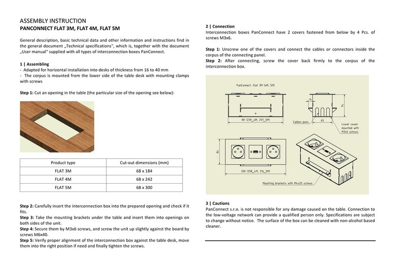
Hilfs- und Signalkontaktblock, Anschlussstützpunkt
Bloc de contact auxiliaire et de signalisation, Cloison de connexion
Auxiliary and signal contact blocks, Connection support
Contatto ausiliario e di segnalazione, Punto di supporto
Warning! Installation by person with electrotechnical expertise only.
Warnung! Installation nur durch elektrotechnische Fachkraft.
Avvertenza! Fare installare solo da un elettricista qualificato.
Avertissement! Installation uniquement par des personnes qualifiées en électrotechnique.
¡Advertencia! La instalación deberá ser realizada únicamente por electricistas especializados.
2CCC451021M0103 (20V3510.c)
Par appareil de protection, on peut monter:
1 bloc de contact auxiliaire
ou 1 bloc de contact de signalisation
ou 2 blocs de contact auxiliaires
ou 1 bloc de contact auxiliaire et
1 bloc de contact de signalisation.
Test de fonctionnement
Après le montage, le bon fonctionnement du bloc de
contact auxiliaire et de signalisation doit être testé. Vérifiez
aussi avec un appareil approprié si les contacts auxiliaires
et de signalisation ont commuté. Sur les blocs de contact
de signalisation, le petit bouton orange doit faire clairement
saillie.
Par la pressiondubouton-testgris, le contact designalisation
doit s’enclencher. Après chaque déclenchement, il faut
ramener le contact de signalisation en position initiale à
l’aide du bouton Reset de couleur orange.
Mise en place des contacts auxiliares et de
signalisation sur l'appareil:
Disjoncteur de ligne au choix à gauche ou à droite
Interrupteur différentiel 4 pôles à droite
Interrupteur différentiel 2 pôles à droite
Interrupteur différentiel/disjoncteur de ligne à gauche
Les contacts auxiliaires et de signalisation pour
profilé support SMISSLINE CLASSIC ne peuvent être
montés sur des systèmes enfichables SMISSLINE.
Montage à droit
Fig. 1 Mettre en place la tige de liaison conformément
à l'établissement du contact de l'interrupteur
différentiel ou du disjoncteur de ligne.
Démontage à droit
Fig. 2
Montage / Démontage à gauche
Fig. 3 / Fig. 4
Gain de place sur le système de socle
Un positionnement en alternance des contacts auxiliai-
res et de signalisation permet de réduire la largeur de
configuration sur le système de socle. Un boîtier vide pour
les contacts auxiliaires et de signalisation n‘est donc pas
nécessaire.
Etablissement du contact des barres
auxiliaires La et Lb
Fig. 5
Contact de signalisation pour l'alarme
commune
Fig. 6 Le montage du contact de signalisation de 9 mm
de large devra se faire de préférence à gauche et
à droite du sectinneur de puissance.
Raccord de la cloison de connexion
Fig. 7 Cloison de connexion et contacts auxiliaires et
de signalisation avec alimentation par les bornes
auxiliaires.
Désignation du contact
Fig. 8
Jan. 2016
Plazieren von Hilfs- oder Signalkontakte
am Gerät:
Leitungsschutzschalter wahlweise links oder rechts
4poliger Fehlerstromschutzschalter rechts
2poliger Fehlerstromschutzschalter rechts
Fehlerstrom-Leitungsschutzschalter links
Hilfs- und Signalkontakte SMISSLINE CLASSIC Trag-
schienen-Geräte sind nicht an SMISSLINE Geräte Steck-
systeme anbaubar.
Montage rechts
Fig. 1 Verbindungsstift bei Version Rechts, für Anbau
LS oder FI4, entsprechend entfernen.
Demontage rechts
Fig. 2
Montage / Demontage links
Fig. 3 / Fig. 4
Platzeinsparung auf dem Stecksockelsystem
Durch abwechselndes Plazieren der HK/SK links und
rechts kann auf dem Stecksockelsystem Smissline die Bau-
breite reduziert werden. Dadurch ist mit einem HK oder SK
kein Leergehäuse notwendig.
Kontaktierung der Hilfsstromschienen La und
Lb
Fig. 5
Signalkontakt für Sammelalarm
Fig. 6 Der Anbau des 9 mm breite Signalkontakt
erfolgt vorteilhaft links und rechts des
Leitungsschutzschalter.
Anschluss Anschlussstützpunkt
Fig. 7 Anschlussstützpunkt und HK oder SK mit
Einspeisung über die Hilfsstromschienen La, Lb.
Kontaktbezeichnung
Fig. 8
Garantie
Le bon fonctionnement est garanti lorsque les opérations de
montage décrites dans ces instructions ont été effectuées
correctement et que les contrôles de bon fonctionnement
ont été faits avant et pendant l'exploitation selon la
description donnée dans les présentes instructions.
Sécurité
Ne procéder à aucune sorte de réparation sur les contacts
auxiliaire/signalisation.
Elimination
Les appareils défectueux sont à éliminer en tant que
déchets spéciaux sur les lieux de collecte prévus à cet effet.
Respecter les prescriptions nationales ou régionales.
Description de fonctionnement
Les contacts auxiliaires se commutent simultanément
avec les contacts de l'appareil de protection (actionnés
manuellement ou automatiquement).
Les contacts de signalisation se commutent en cas de
déclenchement de l'appareil de protection à la suite de
court-circuit ou de courant de défaut.
Guarantee
The safe operation is assured if the assembly work has
been carried out according to these user instructions.
Safety
Repairs may not be carried out to auxiliary/signal contacts.
Disposal
Faulty products should be treated as hazardous waste and
disposed of in an appropriate manner. National or regional
regulations regarding the disposal of hazardous waste
should be adhered to.
Function description
Auxiliary contacts switch simultaneously with the contacts of
the protective device (actuated manually or automatically)
Signal contacts operate only when the protective device
has electrically tripped due to short circuit or residual
current.
The following can be installed per protective device:
1 auxiliary contact block
or 1 signal contact block
or 2 auxiliary contact blocks
or 1 auxiliary and 1 signal contact block.
Function test
After assembly, the correct functioning of the auxiliary and
signal contact blocks must be checked. Check also, by
means of suitable testing equipment, whether the auxiliary
and signal contacts have switched correctly. For the signal
contact blocks, the orange button must clearly protrude.
When the grey test button is pressed, the signal contact
must operate. After each operation, the signal contact must
be reset, by means of the orange-coloured reset button.
Positioning auxiliary or signal contacts on the
device:
Miniature circuit-breaker optionally left or right
4-pole residual-current circuit-breaker right
2-pole residual-current circuit-breaker right
Residual current operated circuit break-
er with overcurrent protection left
SMISSLINE CLASSIC bearing rail auxiliary and signal
contacts cannot be fitted to SMISSLINE plug-in systems.
Assembly right
Fig. 1 Position the connecting pin in accordance with the
contacting of the residual-current circuit-breaker
or miniature circuit-breaker.
Disconnection right
Fig. 2
Assembly / Disconnection left
Fig. 3 / Fig. 4
Saving space on the plug-in socket system
Alternately placing the auxiliary contact/signal contact
on the left and right can reduce the overall width on the
Smissline plug-in socket system. It means that no dummy
housing is required with an auxiliary contact or signal
contact.
Contacting auxiliary busbars La und Lb
Fig. 5
Signal contact for group alarm
Fig. 6 It is advantageous to mount the 9 mm-wide signal
contact to the left and right of the miniature circuit-
breaker.
Connection of connection support
Fig. 7 Connection support and auxiliary contact or signal
contact with power supply via auxiliary busbars
La, Lb.
Contact designation
Fig. 8

