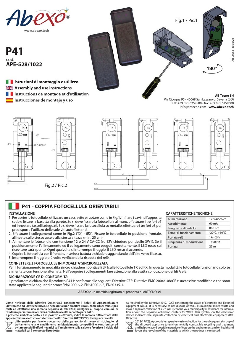
Abexo RM620 User manual

1
www.abtecno.com
www.aperioaccess.it www.aperioaccess.it
RM620 DEUTSCH
DSW3 ON
(Normaler Betrieb)
(Default)
DSW3 OFF
(Positive Sicherheit)
Tab. 2
EINSTELLUNG DER REICHWEITE
Durch die Neigung des Bewegungsmelders und die Position des DIP-Switch 4 ist es
möglich, unterschiedliche Erfassungsbereiche zu erhalten (Abb. 3). Über den Trimmer
TR1, der sich im unteren Bereich des Bewegungsmelders befindet (Abb. 1-F), kann
diese Einstellung optimiert werden, damit nur der gewünschte Bereich anspricht.
AS: hohe Empfindlichkeit
BS: niedrige Empfindlichkeit
Angaben in Meter
Abb. 3
EINSTELLUNG DER HALTEZEIT DES KONTAKTS
Den Trimmer TR2 im unteren Bereich des Bewegungsmelders (Abb. 1-E) betätigen, um
die gewünschte Haltezeit in einem Intervall zwischen 1 – 6 Sekunden zu erhalten.
16
RM620 ITALIANO
Il rivelatore a microonde RM620 è un dispositivo per il comando di portoni industriali e
porte automatiche. Può essere installato ad una altezza compresa tra i 3 e 6 metri
garantendo aree di copertura comprese tra i 3 e i 30 metri quadrati.
Esso interviene in presenza di movimenti di persone o automezzi all’interno di un’area
controllata.
RM620 è sviluppato in tecnologia planare e può essere configurato in modalità
monodirezionale (può rivelare indipendentemente i due versi di direzione avanti o
indietro) o bidirezionale (rivela entrambi i versi di direzione). Un microprocessore
elabora i segnali ricevuti, generati per effetto Doppler, e invia all’uscita un consenso al
comando.
Un LED posto sulla parte frontale indica l’avvenuto movimento all’interno dell’area
controllata.
SPECIFICHE TECNICHE
Tensione di alimentazione
12 – 24 VAC/12 - 30 VDC
Corrente di alimentazione
50 mA max
Frequenza operativa
9,90 GHz
Potenza in uscita (EIRP)
≤14 dBm
Portata
1 – 10 m regolabile
Durata comando relè
1 – 6 s regolabile
Grado di protezione
IP 65
Altezza di installazione
6 m max
Velocità rilevabile
0,1 m/s minima
Contatto relè
1A - 24 VAC/DC
Orientabilità verticale
0-60°
Orientabilità orizzontale
+/- 45°
Temperatura di funzionamento
- 20 °C ÷+ 50 °C
Dimensioni / Peso
160x95x110 mm / 500 g
Garanzia
24 mesi
NOTA: La fonte di alimentazione deve essere SELV (alimentatore certificato o trasformatore di sicurezza)
in conformità alle norme CEI EN 41003:1993
Si dichiara che tale prodotto RM620 risulta essere conforme ai requisiti essenziali della direttiva 99/05/EC
(R&TTE).
1
BS (Neig. 60°)
AS (Neig. 45°)
®

2
www.abtecno.com
www.aperioaccess.it www.aperioaccess.it
RM620 ITALIANO
IMPOSTAZIONE DELLA FUNZIONE
E’ possibile configurare il rivelatore RM620 in modalità mono (un solo verso di direzione)
o bi (entrambi i versi di direzione).
Asportare il tappo in gomma posto nella parte inferiore del rivelatore (Fig.1-A) e utilizzare
il dip-switch (Fig.1-B) per impostare la funzione desiderata, scegliendola tra le disponibili
descritte in tabella:
DSW1
DSW2
DSW4
SENSIBILITA’
CONDIZIONE
OFF
-
ON
Bassa
Vengono rivelati entrambi i versi
OFF
-
OFF
Alta
Vengono rivelati entrambi I versi
ON
OFF
ON
Bassa
Viene rivelato l’avvicinamento al sensore (defalut)
ON
OFF
OFF
Alta
Viene rivelato l’ avvicinamento al sensore
ON
ON
ON
Bassa
Viene rivelato l’allontanamento dal sensore
ON
ON
OFF
Alta
Viene rivelato l’allontanamento dal sensore
FISSAGGIO E ORIENTAMENTO
Il rivelatore RM620 può essere installato centralmente o lateralmente alla porta, su
strutture prive di vibrazione e ad una altezza massima di 6 m, sia a parete che a soffitto
(servirsi della dima fornita per la preparazione dei fori).
Fissare l’apparecchiatura, utilizzando i fori predisposti, rimuovere il coperchio inferiore
(Fig.2-A) e allentare la vite che blocca l’ orientamento del rivelatore. Orientare il rivelatore
verso l’area da controllare e bloccare.
Qualora fosse richiesta un’installazione del rivelatore tramite staffa di prolunga,
richiedere la squadretta adattatrice (opzionale).
Per un corretto funzionamento non installare RM620 :
- rivolto verso parti in movimento della porta
- rivolto verso lampade fluorescenti (mantenere una distanza minima di 2 m)
- rivolto verso zone in cui la pioggia possa provocare flussi di acqua
Tali condizioni potrebbero causare comandi di apertura indesiderati.
COLLEGAMENTI ELETTRICI
Utilizzando il cavo pre-cablato effettuare i collegamenti secondo tabella 1 e
successivamente alimentare il rivelatore.
2
RM620 DEUTSCH
Die auf der Vorderseite des Bewegungsmelders vorhandene LED (Abb. 2-B) zeigt
während der gesamten Anzugszeit des Relais die erfolgte Erfassung einer Bewegung
an.
AEF B B A
Abb.1 Abb.2
Tab. 1
EINSTELLUNG DES RELAISKONTAKTS
Der Bewegungsmelder RM620 verfügt über ein Relais mit Wechsler.
Durch die Einstellung des DIP-Switch 3 (Abb. 1-B) im unteren Bereich des
Bewegungsmelders ist es möglich, die in der Tabelle 2 beschriebenen Kombinationen zu
erhalten.
Diese Bedingungen gelten bei gespeistem Gerät.
15
Drahtfarbe
Beschreibung
Rot
12-24 V AC/DC
Schwarz
12-24 V AC/DC
Grün
COM Relaiskontakt
Gelb
Schließer (bei nicht gespeistem Gerät)
Blau
Öffner (bei nicht gespeistem Gerät)
www.aperioaccess.it www.aperioaccess.it
RM620 DEUTSCH
EINSTELLUNG DER FUNKTION
Der Bewegungsmelder RM620 kann im unidirektionalen Modus (nur eine Richtung)
oder im bidirektionalen Modus (beide Richtungen) konfiguriert werden.
Den Gummistopfen im unteren Bereich des Bewegungsmelders (Abb. 1-A) abnehmen
und den DIP-Switch (Abb. 1-B) verwenden, um die gewünschte Funktion aus den in der
Tabelle beschriebenen, verfügbaren Funktionen auszuwählen:
DSW1
DSW2
DSW4
EMPFINDLICHKEIT
ZUSTAND
OFF
-
ON
Niedrig
Es werden beide Richtungen erfasst
OFF
-
OFF
Hoch
Es werden beide Richtungen erfasst
ON
OFF
ON
Niedrig
Es wird die Annäherung an den Sensor erfasst
(Default)
ON
OFF
OFF
Hoch
Es wird die Annäherung an den Sensor erfasst
ON
ON
ON
Niedrig
Es wird die Entfernung vom Sensor erfasst
ON
ON
OFF
Hoch
Es wird die Entfernung vom Sensor erfasst
BEFESTIGUNG UND AUSRICHTUNG
Der Bewegungsmelder RM620 kann in der Mitte oder seitlich an der Tür, an
vibrationsfreien Strukturen und in einer maximalen Höhe von 6 m, sowohl an der Wand
als auch an der Decke angebracht werden (zur Vorbereitung der Bohrungen die
mitgelieferte Schablone verwenden).
Das Gerät befestigen, indem die vorbereiteten Bohrungen verwendet werden, die untere
Abdeckung (Abb. 2-A) entfernen und die Feststellschraube für die Ausrichtung lockern.
Den Bewegungsmelder auf den zu überwachenden Bereich ausrichten und arretieren.
Sollte eine Installation des Bewegungsmelders mit Hilfe des Verlängerungsbügels
erforderlich sein, den Adapterwinkel (optional) anfordern.
Für einen korrekten Betrieb sollte RM620 so installiert werden, dass dieser nicht in
Richtung:
- sich bewegender Teile der Tür
- von Leuchtstofflampen (einen Mindestabstand von 2 m einhalten)
- von Bereichen, in denen Regenwasser herabfließen kann
zeigt.
Solche Situationen könnten ungewünschte Öffnungsvorgänge bewirken.
ELEKTRISCHE ANSCHLÜSSE
Unter Verwendung des vorverdrahteten Kabels die Anschlüsse gemäß Tabelle 1
ausführen und den Bewegungsmelder dann mit Strom versorgen.
14
RM620 ITALIANO
Il LED presente sulla parte frontale del rivelatore (Fig.2-B) segnalerà, per tutto il tempo
di eccitazione del relè, l’avvenuta rivelazione di un movimento.
AEF B B A
Fig.1 Fig.2
Tab.1
IMPOSTAZIONE DEL CONTATTO RELE’
Il rivelatore RM620 dispone di un relè con contatto scambio.
Mediante l’impostazione del dip-switch 3 (Fig.1-B) posto nella parte inferiore del
rivelatore è possibile ottenere le combinazioni descritte in tabella 2.
Tali condizioni sono valide a dispositivo alimentato.
3
Colore filo
Descrizione
Rosso
12-24 V AC/DC
Nero
12-24 V AC/DC
Verde
COM contatto relè
Giallo
Contatto NO (a dispositivo non alimentato)
Blu
Contatto NC (a dispositivo non alimentato)

3
www.abtecno.com
www.aperioaccess.it www.aperioaccess.it
RM620 DEUTSCH
EINSTELLUNG DER FUNKTION
Der Bewegungsmelder RM620 kann im unidirektionalen Modus (nur eine Richtung)
oder im bidirektionalen Modus (beide Richtungen) konfiguriert werden.
Den Gummistopfen im unteren Bereich des Bewegungsmelders (Abb. 1-A) abnehmen
und den DIP-Switch (Abb. 1-B) verwenden, um die gewünschte Funktion aus den in der
Tabelle beschriebenen, verfügbaren Funktionen auszuwählen:
DSW1
DSW2
DSW4
EMPFINDLICHKEIT
ZUSTAND
OFF
-
ON
Niedrig
Es werden beide Richtungen erfasst
OFF
-
OFF
Hoch
Es werden beide Richtungen erfasst
ON
OFF
ON
Niedrig
Es wird die Annäherung an den Sensor erfasst
(Default)
ON
OFF
OFF
Hoch
Es wird die Annäherung an den Sensor erfasst
ON
ON
ON
Niedrig
Es wird die Entfernung vom Sensor erfasst
ON
ON
OFF
Hoch
Es wird die Entfernung vom Sensor erfasst
BEFESTIGUNG UND AUSRICHTUNG
Der Bewegungsmelder RM620 kann in der Mitte oder seitlich an der Tür, an
vibrationsfreien Strukturen und in einer maximalen Höhe von 6 m, sowohl an der Wand
als auch an der Decke angebracht werden (zur Vorbereitung der Bohrungen die
mitgelieferte Schablone verwenden).
Das Gerät befestigen, indem die vorbereiteten Bohrungen verwendet werden, die untere
Abdeckung (Abb. 2-A) entfernen und die Feststellschraube für die Ausrichtung lockern.
Den Bewegungsmelder auf den zu überwachenden Bereich ausrichten und arretieren.
Sollte eine Installation des Bewegungsmelders mit Hilfe des Verlängerungsbügels
erforderlich sein, den Adapterwinkel (optional) anfordern.
Für einen korrekten Betrieb sollte RM620 so installiert werden, dass dieser nicht in
Richtung:
- sich bewegender Teile der Tür
- von Leuchtstofflampen (einen Mindestabstand von 2 m einhalten)
- von Bereichen, in denen Regenwasser herabfließen kann
zeigt.
Solche Situationen könnten ungewünschte Öffnungsvorgänge bewirken.
ELEKTRISCHE ANSCHLÜSSE
Unter Verwendung des vorverdrahteten Kabels die Anschlüsse gemäß Tabelle 1
ausführen und den Bewegungsmelder dann mit Strom versorgen.
14
RM620 ITALIANO
Il LED presente sulla parte frontale del rivelatore (Fig.2-B) segnalerà, per tutto il tempo
di eccitazione del relè, l’avvenuta rivelazione di un movimento.
AEF B B A
Fig.1 Fig.2
Tab.1
IMPOSTAZIONE DEL CONTATTO RELE’
Il rivelatore RM620 dispone di un relè con contatto scambio.
Mediante l’impostazione del dip-switch 3 (Fig.1-B) posto nella parte inferiore del
rivelatore è possibile ottenere le combinazioni descritte in tabella 2.
Tali condizioni sono valide a dispositivo alimentato.
3
Colore filo
Descrizione
Rosso
12-24 V AC/DC
Nero
12-24 V AC/DC
Verde
COM contatto relè
Giallo
Contatto NO (a dispositivo non alimentato)
Blu
Contatto NC (a dispositivo non alimentato)

4
www.abtecno.com
www.aperioaccess.it www.aperioaccess.it
RM620 ITALIANO
DSW3 ON
(Funzionamento normale)
(default)
DSW3 OFF
(Sicurezza positiva)
Tab.2
REGOLAZIONE DELLA PORTATA
Mediante l’ inclinazione del rivelatore e la posizione del dip-switch 4 è possibile ottenere
aree controllate ben distinte (Fig.3). Mediante il trimmer TR1, posto nella parte inferiore
del rivelatore (Fig.1-F), è possibile ottimizzare tale regolazione al fine di rendere sensibile
la sola area interessata.
AS: alta sensibilità
BS: bassa sensibilità
Dimensioni in metri
Fig. 3
REGOLAZIONE DEL TEMPO DI MANTENIMENTO DEL CONTATTO
Agire sul trimmer TR2 posto nella parte inferiore del rivelatore (Fig.1-E) per ottenere il
tempo di mantenimento desiderato in un intervallo compreso tra
1 – 6 sec.
4
RM620 DEUTSCH
Der Mikrowellen-Bewegungsmelder RM620 dient für die Steuerung von Industrietoren
und automatischen Türen. Er kann in einer Höhe zwischen 3 und 6 Metern installiert
werden und garantiert Erfassungsbereiche zwischen 3 und 30 Quadratmetern.
Er spricht bei Bewegungen von Personen oder Kraftfahrzeugen innerhalb des
überwachten Bereiches an.
RM620 ist in Planartechnologie entwickelt und kann im unidirektionalen Modus (kann
unabhängig die beiden Richtungen vorwärts oder rückwärts erfassen) oder im
bidirektionalen Modus (erfasst beide Richtungen) konfiguriert werden. Ein
Mikroprozessor wertet die durch Dopplereffekt erzeugten, empfangenen Signale aus und
sendet eine Freigabe zur Betätigung an den Ausgang.
Eine LED auf der Vorderseite zeigt die erfolgte Bewegung innerhalb des überwachten
Bereiches an.
TECHNISCHE SPEZIFIKATIONEN
Versorgungsspannung
12 – 24 VAC/12 - 30 VDC
Versorgungsstrom
50 mA max.
Betriebsfrequenz
9,90 GHz
Ausgangsleistung (EIRP)
≤14 dBm
Reichweite
1 – 10 m einstellbar
Dauer Relaisbetätigung
1 – 6 s einstellbar
Schutzart
IP 65
Einbauhöhe
6 m max.
Erfassbare Geschwindigkeit
0,1 m/s min.
Relaiskontakt
1A - 24 VAC/DC
Vertikale Ausrichtbarkeit
0-60°
Horizontale Ausrichtbarkeit
+/- 45°
Betriebstemperatur
- 20 °C ÷+ 50 °C
Abmessungen / Gewicht
160x95x110 mm / 500 g
Garantie
24 Monate
INWEIS: Die Versorgungsquelle muss in Übereinstimmung mit den Vorschriften CEI EN 41003:1993 SELV
sein (zertifiziertes Netzgerät oder Sicherheitstransformator).
Es wird erklärt, dass das Gerät RM620 die wesentlichen Anforderungen der Richtlinie 99/05/EG (R&TTE)
bezüglich der harmonisierten Bestimmungen für Funksysteme laut Art. 3.2 der Gesetzesverordnung vom
9.5.2001 Nr. 269:EN300440-2 V 1.1.2 erfüllt.
13
BS (Incl. 60°)
AS (Incl. 45°)
www.aperioaccess.it www.aperioaccess.it
RM620 FRANÇAIS
DSW3 ON
(Fonctionnement normal)
(par défaut)
DSW3 OFF(Sécurité
positive)
Tab.2
RÉGLAGE DE LA PORTÉE
Afin d’obtenir des zones contrôlées bien distinctes (Fig. 3), il suffit de jouer sur
l’inclinaison du détecteur et sur la position du sélecteur à positions multiples (dip-switch
4). A l’aide du trimmer TR1, situé dans la partie inférieure du détecteur (Fig.1-F), il est
possible d’affiner ce réglage pour que seule la zone choisie ne soit couverte.
HS : Haute Sensibilité
BS : Basse Sensibilité
Dimensions en mètres
Fig. 3
RÉGLAGE DU DÉLAI DE MAINTIEN DU CONTACT
Utilisez le trimmer TR2 dans la partie inférieure du détecteur (Fig.1-E) pour obtenir le
délai de maintien du contact souhaité (1 à 6 secondes).
12
RM620 ENGLISH
The RM620 microwave movement detector controls the opening of factory gates and
automatic doors. It works in the K band. It can be installed at a height ranging from 3 to 6
metres and guarantees the surveillance of an area from 3 to 30 square metres .
The device will be automatically activated by moving persons or vehicles within the
controlled perimeter.
RM620 has been developed using planar technology, and can be set in mono-
directional (to detect movement either in forward or backward direction) or bi-
directional (activated by movement in both directions). A microprocessor processes the
signals received – generated through a Doppler effect – and sends an OK to the opening
command.
A LED on the front panel indicates that movement has taken place inside the controlled
area.
TECHNICAL DATA
Power voltage
12 – 24 VAC/12 - 30 VDC
Power current
max. 50 mA
Operative frequency
9.90 GHz
Output Power (EIRP)
≤14 dBm
Range
1 – 10 m adjustable
Relay control time
1 – 6 s adjustable
Degree of protection
IP 65
Installation height
max. 6 m
Detectable speed
0.1 m/s minimum
Relay contact
1A - 24 VAC/DC
Vertical directionality
0-60°
Horizontal directionality
+/- 45°
Operating temperature
- 20 °C to + 50 °C
Dimensions/weight
160x95x110 mm / 500 g
Warranty
24 months
NOTE: A SELV power source must be used (certified power supply unit or safety transformer) in
compliance with CEI EN 41003:1993 standard.
We hereby declare that RM620 complies with the essential requirements of Directive 99/05/EC (R&TTE)
harmonised radio standard pursuant to Art. 3.2 of Italian Law No. 269 dated 9.5.2001: EN300440-2 V 1.1.2
5
BS (Incl. 60°)
HS (Incl. 45°)
BMPEUROPE s.r.l.
Via Torino, 64/ter – 12040 VEZZA D’ ALBA (CN)
4
APRO 20 ITALIANO
DSW3 ON
Funzionamento radar di apertura
DSW3 OFF
Funzionamento radar di sicurezza
Tab.2
REGOLAZIONE DELLA PORTATA
Mediante l’ inclinazione del rivelatore e la posizione del dip-switch 4 è possibile ottenere
aree controllate ben distinte (Fig.3). Mediante il trimmer TR1, posto nella parte inferiore del
rivelatore (Fig.1-F), è possibile ottimizzare tale regolazione al fine di rendere sensibile la
sola area interessata.
AS: alta sensibilità
BS: bassa sensibilità
Dimensioni in metri
Fig. 3
REGOLAZIONE DEL TEMPO DI MANTENIMENTO DEL CONTATTO
Agire sul trimmer TR2 posto nella parte inferiore del rivelatore (Fig.1-E) per ottenere il
tempo di mantenimento desiderato in un intervallo compreso tra 1 – 6 sec.
BS (Incl. 60°)
AS (Incl. 45°)

5
www.abtecno.com
www.aperioaccess.it www.aperioaccess.it
RM620 FRANÇAIS
DSW3 ON
(Fonctionnement normal)
(par défaut)
DSW3 OFF(Sécurité
positive)
Tab.2
RÉGLAGE DE LA PORTÉE
Afin d’obtenir des zones contrôlées bien distinctes (Fig. 3), il suffit de jouer sur
l’inclinaison du détecteur et sur la position du sélecteur à positions multiples (dip-switch
4). A l’aide du trimmer TR1, situé dans la partie inférieure du détecteur (Fig.1-F), il est
possible d’affiner ce réglage pour que seule la zone choisie ne soit couverte.
HS : Haute Sensibilité
BS : Basse Sensibilité
Dimensions en mètres
Fig. 3
RÉGLAGE DU DÉLAI DE MAINTIEN DU CONTACT
Utilisez le trimmer TR2 dans la partie inférieure du détecteur (Fig.1-E) pour obtenir le
délai de maintien du contact souhaité (1 à 6 secondes).
12
RM620 ENGLISH
The RM620 microwave movement detector controls the opening of factory gates and
automatic doors. It works in the K band. It can be installed at a height ranging from 3 to 6
metres and guarantees the surveillance of an area from 3 to 30 square metres .
The device will be automatically activated by moving persons or vehicles within the
controlled perimeter.
RM620 has been developed using planar technology, and can be set in mono-
directional (to detect movement either in forward or backward direction) or bi-
directional (activated by movement in both directions). A microprocessor processes the
signals received – generated through a Doppler effect – and sends an OK to the opening
command.
A LED on the front panel indicates that movement has taken place inside the controlled
area.
TECHNICAL DATA
Power voltage
12 – 24 VAC/12 - 30 VDC
Power current
max. 50 mA
Operative frequency
9.90 GHz
Output Power (EIRP)
≤14 dBm
Range
1 – 10 m adjustable
Relay control time
1 – 6 s adjustable
Degree of protection
IP 65
Installation height
max. 6 m
Detectable speed
0.1 m/s minimum
Relay contact
1A - 24 VAC/DC
Vertical directionality
0-60°
Horizontal directionality
+/- 45°
Operating temperature
- 20 °C to + 50 °C
Dimensions/weight
160x95x110 mm / 500 g
Warranty
24 months
NOTE: A SELV power source must be used (certified power supply unit or safety transformer) in
compliance with CEI EN 41003:1993 standard.
We hereby declare that RM620 complies with the essential requirements of Directive 99/05/EC (R&TTE)
harmonised radio standard pursuant to Art. 3.2 of Italian Law No. 269 dated 9.5.2001: EN300440-2 V 1.1.2
5
BS (Incl. 60°)
HS (Incl. 45°)
®

6
www.abtecno.com
www.aperioaccess.it www.aperioaccess.it
RM620 ENGLISH
SETTING FOR OPERATION
The RM620 movement detector can be configured in mono direction mode (one direction
only) or in bi directional mode (in both directions).
Remove the rubber plug from the lower section of the detector (Fig. 1-A) and set the
required function through the dip-switch (Fig. 1-B), choosing from the possibilities
indicated in the table:
DSW1
DSW2
DSW4
SENSITIVITY
CONDITION
OFF
-
ON
Low
Movement is detected in both directions
OFF
-
OFF
High
Movement is detected in both directions
ON
OFF
ON
Low
Approach to the sensor is detected
ON
OFF
OFF
High
Approach to the sensor is detected
ON
ON
ON
Low
Movement away from the sensor is detected
ON
ON
OFF
High
Movement away from the sensor is detected
ASSEMBLY AND ORIENTATION
RM620 can be installed at the centre of the door to be controlled or on the side, on non-
vibrating structures (walls or ceiling) and at a maximum height of 6 m. Use the template
supplied to prepare the holes.
Fasten the device using the prepared holes, remove the lower cover (Fig. 2-A) and
loosen the screw that blocks the detector orientation. Direct the detector toward the area
to be controlled and lock in that position.
For correct operation, do not install RM620 :
- facing the moving parts of the door
- facing fluorescent lights (minimum distance 2m)
- facing areas where rain could provoke water fluxes
These conditions could activate the device and cause the unwanted opening of the door.
ELECTRICAL CONNECTIONS
Connect the pre-wired cable as indicated in table 1 then power the detector.
6
RM620 FRANÇAIS
La DEL présente sur la façade du détecteur (Fig.2-B) signalera la présence d’un
mouvement pendant toute la durée de l’excitation du relais.
AEF B B A
Fig.1 Fig.2
Tab.1
RÉGLAGE DU CONTACT DU RELAIS
Le détecteur RM620 dispose d’un relais avec un contact à permutation.
Le tableau 2 illustre les combinaisons possibles grâce au réglage du dip-switch 3 (Fig.1-
B) situé dans la partie basse du détecteur.
Ces conditions ne sont vraies que lorsque le dispositif est alimenté.
11
Couleur du
câble
Description
Rouge
12-24 V CA/CC
Noir
12-24 V CA/CC
Vert
COM contact relais
Jaune
Contact NO (à dispositif non alimenté)
Bleu
Contact NC (à dispositif non alimenté)

7
www.abtecno.com
www.aperioaccess.it www.aperioaccess.it
RM620 FRANÇAIS
CHOIX DE LA FONCTION
Vous pouvez choisir de faire fonctionner votre détecteur RM620 en mode
unidirectionnel (une seule direction) ou en mode bidirectionnel (deux directions).
Déposez le bouchon en caoutchouc situé dans la partie basse de votre détecteur (Fig.1-
A) et utilisez le dip-switch (Fig.1-B) pour choisir la fonction souhaitée, en choisissant
parmi celles décrites dans le tableau suivant :
DSW1
DSW2
DSW4
SENSIBILITÉ
CONDITION
OFF
-
ON
Basse
Les deux directions sont détectées
OFF
-
OFF
Haute
Les deux directions sont détectées
ON
OFF
ON
Basse
Seule l’approche au capteur est détectée (défaut)
ON
OFF
OFF
Haute
Seule l’approche au capteur est détectée
ON
ON
ON
Basse
Seul l’éloignement du capteur est détecté
ON
ON
OFF
Haute
Seul l’éloignement du capteur est détecté
FIXATION ET ORIENTATION
Le détecteur RM620 peut être installé centralement ou latéralement par rapport à la
porte, fixé sur une structure sans vibrations et à une hauteur de 6 mètres maxi, sur
cloison ou au plafond (servez-vous du gabarit fourni pour préparer les trous).
Fixez l’appareil au moyen des trous prévus à cet effet, déposez le couvercle inférieur
(Fig.2-A) et desserrez la vis qui bloque l’orientation du détecteur. Orientez le détecteur
en direction de la zone à contrôler et fixez-le ainsi.
Si l’installation du détecteur devait nécessiter d’une rallonge, demandez en option
l’équerre-support prévue à cet effet.
Pour que l’appareil fonctionne correctement évitez d’installer RM620 :
- en direction des zones en mouvement de la porte elle-même
- en direction de lampes fluorescentes (respectez une distance d’au moins 2 mètres)
- en direction des zones susceptibles d’être soumises à des écoulements d’eau
Ces conditions pourraient entraîner des ouvertures inopinées.
BRANCHEMENTS ÉLECTRIQUES
Utilisez le cordon pré-câblé pour effectuer les branchements comme indiqué dans le
tableau 1 puis alimentez le détecteur.
10
RM620 ENGLISH
The LED on the detector front panel (Fig. 2-B) will indicate the detection of a movement,
for all the time the relay is excited.
AEF B B A
Fig.1 Fig.2
Tab.1
RELAY CONTACT SETTING
RM620 has a relay with switching contact.
According to the setting of the dip-switch 3 (Fig. 1-B) in the lower section of the detector,
the combinations described in table 2 can be obtained.
These conditions are valid when the device is powered.
7
Wire colour
Description
Red
12-24 V AC/DC
Black
12-24 V AC/DC
Green
COM relay contact
Yellow
NO contact (when device is not powered)
Blue
NC contact (when device is not powered)

8
www.abtecno.com
www.aperioaccess.it www.aperioaccess.it
RM620 ENGLISH
DSW3 ON
(Normal operation)
DSW3 OFF
(Positive safety)
Tab.2
SETTING OF DETECTION RANGE
It is possible to define the controlled area by changing the inclination of the detector and
the position of dip-switch 4 (Fig. 3). With trimmer TR1, located on the lower section of the
detector (Fig. 1-F), the regulation can be optimised to activate detection only for the
desired area.
AS: high sensitivity
BS: low sensitivity
Dimensions in metres
Fig. 3
REGULATION OF CONTACT DURATION
The trimmer TR2 on the lower section of the detector (Fig. 1-E) can be used to set the
desired duration of the electric contact, which can vary from 1 – 6 seconds.
8
RM620 FRANÇAIS
Le détecteur à micro-ondes RM620 est un dispositif pour commander portes et portails
automatiques. Il peut être installé à une hauteur comprise entre 3 et 6 mètres
garantissant ainsi une zone de couverture comprise entre 3 et 30 m2.
Il intervient lorsqu’il détecte des mouvements de personnes ou de véhicules à l’intérieur
d’une zone contrôlée.
RM620 bénéficie d’une technologie planaire et peut être configuré en mode
unidirectionnel (discerne indépendamment les deux directions du déplacement :
approche ou éloignement) ou bidirectionnel (détecte les deux directions de
déplacement : approche et éloignement). Un microprocesseur traite les signaux reçus,
générés par effet Doppler, et envoie à la sortie un consensus au dispositif de commande.
Une DEL en façade indique la présence de mouvement à l’intérieur de la zone contrôlée.
CARACTÉRISTIQUES TECHNIQUES
Tension d’alimentation
12 – 24 VCA/12 - 30 VCC
Alimentation électrique
50 mA maxi
Fréquence opérationnelle
9,90 GHz
Puissance à la sortie (EIRP)
≤14 dBm
Portée
1 - 10 m réglable
Durée de la commande relais
1 - 6 s réglable
Degré de protection
IP 65
Hauteur d’installation
6 m maxi
Vitesse détectable
0,1 m/s minimum
Contact relais
1A - 24 VCA/CC
Orientable à la verticale
0-60°
Orientable à l’horizontale
+/- 45°
Température de fonctionnement
- 20 °C / + 50 °C
Dimensions/Poids
160x95x110 mm / 500 g
Garantie
24 mois
REMARQUE : La source d’alimentation doit être "SELV" (VSTF - Voltage de Sécurité Très Faible) donc,
soit un boîtier d’alimentation certifié soit un transformateur de sécurité, conforme aux normes CEI EN
41003:1993
L’appareil RM620 est déclaré conforme aux exigences essentielles de la directive 99/05/EC(R&TTE)
Norme harmonisée sur les ondes radio au titre de l’article 3.2 du décret législatif 9.5.2001 n.269:
EN300440-2 V 1.1.2
9
BS (Incl. 60°)
AS (Incl. 45°)
BMPEUROPE s.r.l.
Via Torino, 64/ter – 12040 VEZZA D’ ALBA (CN)
4
APRO 20 ITALIANO
DSW3 ON
Funzionamento radar di apertura
DSW3 OFF
Funzionamento radar di sicurezza
Tab.2
REGOLAZIONE DELLA PORTATA
Mediante l’ inclinazione del rivelatore e la posizione del dip-switch 4 è possibile ottenere
aree controllate ben distinte (Fig.3). Mediante il trimmer TR1, posto nella parte inferiore del
rivelatore (Fig.1-F), è possibile ottimizzare tale regolazione al fine di rendere sensibile la
sola area interessata.
AS: alta sensibilità
BS: bassa sensibilità
Dimensioni in metri
Fig. 3
REGOLAZIONE DEL TEMPO DI MANTENIMENTO DEL CONTATTO
Agire sul trimmer TR2 posto nella parte inferiore del rivelatore (Fig.1-E) per ottenere il
tempo di mantenimento desiderato in un intervallo compreso tra 1 – 6 sec.
BS (Incl. 60°)
AS (Incl. 45°)

9
www.abtecno.com
www.aperioaccess.it www.aperioaccess.it
RM620 ENGLISH
DSW3 ON
(Normal operation)
DSW3 OFF
(Positive safety)
Tab.2
SETTING OF DETECTION RANGE
It is possible to define the controlled area by changing the inclination of the detector and
the position of dip-switch 4 (Fig. 3). With trimmer TR1, located on the lower section of the
detector (Fig. 1-F), the regulation can be optimised to activate detection only for the
desired area.
AS: high sensitivity
BS: low sensitivity
Dimensions in metres
Fig. 3
REGULATION OF CONTACT DURATION
The trimmer TR2 on the lower section of the detector (Fig. 1-E) can be used to set the
desired duration of the electric contact, which can vary from 1 – 6 seconds.
8
RM620 FRANÇAIS
Le détecteur à micro-ondes RM620 est un dispositif pour commander portes et portails
automatiques. Il peut être installé à une hauteur comprise entre 3 et 6 mètres
garantissant ainsi une zone de couverture comprise entre 3 et 30 m2.
Il intervient lorsqu’il détecte des mouvements de personnes ou de véhicules à l’intérieur
d’une zone contrôlée.
RM620 bénéficie d’une technologie planaire et peut être configuré en mode
unidirectionnel (discerne indépendamment les deux directions du déplacement :
approche ou éloignement) ou bidirectionnel (détecte les deux directions de
déplacement : approche et éloignement). Un microprocesseur traite les signaux reçus,
générés par effet Doppler, et envoie à la sortie un consensus au dispositif de commande.
Une DEL en façade indique la présence de mouvement à l’intérieur de la zone contrôlée.
CARACTÉRISTIQUES TECHNIQUES
Tension d’alimentation
12 – 24 VCA/12 - 30 VCC
Alimentation électrique
50 mA maxi
Fréquence opérationnelle
9,90 GHz
Puissance à la sortie (EIRP)
≤14 dBm
Portée
1 - 10 m réglable
Durée de la commande relais
1 - 6 s réglable
Degré de protection
IP 65
Hauteur d’installation
6 m maxi
Vitesse détectable
0,1 m/s minimum
Contact relais
1A - 24 VCA/CC
Orientable à la verticale
0-60°
Orientable à l’horizontale
+/- 45°
Température de fonctionnement
- 20 °C / + 50 °C
Dimensions/Poids
160x95x110 mm / 500 g
Garantie
24 mois
REMARQUE : La source d’alimentation doit être "SELV" (VSTF - Voltage de Sécurité Très Faible) donc,
soit un boîtier d’alimentation certifié soit un transformateur de sécurité, conforme aux normes CEI EN
41003:1993
L’appareil RM620 est déclaré conforme aux exigences essentielles de la directive 99/05/EC(R&TTE)
Norme harmonisée sur les ondes radio au titre de l’article 3.2 du décret législatif 9.5.2001 n.269:
EN300440-2 V 1.1.2
9
BS (Incl. 60°)
AS (Incl. 45°)
®

10
www.abtecno.com
www.aperioaccess.it www.aperioaccess.it
RM620 FRANÇAIS
CHOIX DE LA FONCTION
Vous pouvez choisir de faire fonctionner votre détecteur RM620 en mode
unidirectionnel (une seule direction) ou en mode bidirectionnel (deux directions).
Déposez le bouchon en caoutchouc situé dans la partie basse de votre détecteur (Fig.1-
A) et utilisez le dip-switch (Fig.1-B) pour choisir la fonction souhaitée, en choisissant
parmi celles décrites dans le tableau suivant :
DSW1
DSW2
DSW4
SENSIBILITÉ
CONDITION
OFF
-
ON
Basse
Les deux directions sont détectées
OFF
-
OFF
Haute
Les deux directions sont détectées
ON
OFF
ON
Basse
Seule l’approche au capteur est détectée (défaut)
ON
OFF
OFF
Haute
Seule l’approche au capteur est détectée
ON
ON
ON
Basse
Seul l’éloignement du capteur est détecté
ON
ON
OFF
Haute
Seul l’éloignement du capteur est détecté
FIXATION ET ORIENTATION
Le détecteur RM620 peut être installé centralement ou latéralement par rapport à la
porte, fixé sur une structure sans vibrations et à une hauteur de 6 mètres maxi, sur
cloison ou au plafond (servez-vous du gabarit fourni pour préparer les trous).
Fixez l’appareil au moyen des trous prévus à cet effet, déposez le couvercle inférieur
(Fig.2-A) et desserrez la vis qui bloque l’orientation du détecteur. Orientez le détecteur
en direction de la zone à contrôler et fixez-le ainsi.
Si l’installation du détecteur devait nécessiter d’une rallonge, demandez en option
l’équerre-support prévue à cet effet.
Pour que l’appareil fonctionne correctement évitez d’installer RM620 :
- en direction des zones en mouvement de la porte elle-même
- en direction de lampes fluorescentes (respectez une distance d’au moins 2 mètres)
- en direction des zones susceptibles d’être soumises à des écoulements d’eau
Ces conditions pourraient entraîner des ouvertures inopinées.
BRANCHEMENTS ÉLECTRIQUES
Utilisez le cordon pré-câblé pour effectuer les branchements comme indiqué dans le
tableau 1 puis alimentez le détecteur.
10
RM620 ENGLISH
The LED on the detector front panel (Fig. 2-B) will indicate the detection of a movement,
for all the time the relay is excited.
AEF B B A
Fig.1 Fig.2
Tab.1
RELAY CONTACT SETTING
RM620 has a relay with switching contact.
According to the setting of the dip-switch 3 (Fig. 1-B) in the lower section of the detector,
the combinations described in table 2 can be obtained.
These conditions are valid when the device is powered.
7
Wire colour
Description
Red
12-24 V AC/DC
Black
12-24 V AC/DC
Green
COM relay contact
Yellow
NO contact (when device is not powered)
Blue
NC contact (when device is not powered)

11
www.abtecno.com
www.aperioaccess.it www.aperioaccess.it
RM620 ENGLISH
SETTING FOR OPERATION
The RM620 movement detector can be configured in mono direction mode (one direction
only) or in bi directional mode (in both directions).
Remove the rubber plug from the lower section of the detector (Fig. 1-A) and set the
required function through the dip-switch (Fig. 1-B), choosing from the possibilities
indicated in the table:
DSW1
DSW2
DSW4
SENSITIVITY
CONDITION
OFF
-
ON
Low
Movement is detected in both directions
OFF
-
OFF
High
Movement is detected in both directions
ON
OFF
ON
Low
Approach to the sensor is detected
ON
OFF
OFF
High
Approach to the sensor is detected
ON
ON
ON
Low
Movement away from the sensor is detected
ON
ON
OFF
High
Movement away from the sensor is detected
ASSEMBLY AND ORIENTATION
RM620 can be installed at the centre of the door to be controlled or on the side, on non-
vibrating structures (walls or ceiling) and at a maximum height of 6 m. Use the template
supplied to prepare the holes.
Fasten the device using the prepared holes, remove the lower cover (Fig. 2-A) and
loosen the screw that blocks the detector orientation. Direct the detector toward the area
to be controlled and lock in that position.
For correct operation, do not install RM620 :
- facing the moving parts of the door
- facing fluorescent lights (minimum distance 2m)
- facing areas where rain could provoke water fluxes
These conditions could activate the device and cause the unwanted opening of the door.
ELECTRICAL CONNECTIONS
Connect the pre-wired cable as indicated in table 1 then power the detector.
6
RM620 FRANÇAIS
La DEL présente sur la façade du détecteur (Fig.2-B) signalera la présence d’un
mouvement pendant toute la durée de l’excitation du relais.
AEF B B A
Fig.1 Fig.2
Tab.1
RÉGLAGE DU CONTACT DU RELAIS
Le détecteur RM620 dispose d’un relais avec un contact à permutation.
Le tableau 2 illustre les combinaisons possibles grâce au réglage du dip-switch 3 (Fig.1-
B) situé dans la partie basse du détecteur.
Ces conditions ne sont vraies que lorsque le dispositif est alimenté.
11
Couleur du
câble
Description
Rouge
12-24 V CA/CC
Noir
12-24 V CA/CC
Vert
COM contact relais
Jaune
Contact NO (à dispositif non alimenté)
Bleu
Contact NC (à dispositif non alimenté)

12
www.abtecno.com
www.aperioaccess.it www.aperioaccess.it
RM620 FRANÇAIS
DSW3 ON
(Fonctionnement normal)
(par défaut)
DSW3 OFF(Sécurité
positive)
Tab.2
RÉGLAGE DE LA PORTÉE
Afin d’obtenir des zones contrôlées bien distinctes (Fig. 3), il suffit de jouer sur
l’inclinaison du détecteur et sur la position du sélecteur à positions multiples (dip-switch
4). A l’aide du trimmer TR1, situé dans la partie inférieure du détecteur (Fig.1-F), il est
possible d’affiner ce réglage pour que seule la zone choisie ne soit couverte.
HS : Haute Sensibilité
BS : Basse Sensibilité
Dimensions en mètres
Fig. 3
RÉGLAGE DU DÉLAI DE MAINTIEN DU CONTACT
Utilisez le trimmer TR2 dans la partie inférieure du détecteur (Fig.1-E) pour obtenir le
délai de maintien du contact souhaité (1 à 6 secondes).
12
RM620 ENGLISH
The RM620 microwave movement detector controls the opening of factory gates and
automatic doors. It works in the K band. It can be installed at a height ranging from 3 to 6
metres and guarantees the surveillance of an area from 3 to 30 square metres .
The device will be automatically activated by moving persons or vehicles within the
controlled perimeter.
RM620 has been developed using planar technology, and can be set in mono-
directional (to detect movement either in forward or backward direction) or bi-
directional (activated by movement in both directions). A microprocessor processes the
signals received – generated through a Doppler effect – and sends an OK to the opening
command.
A LED on the front panel indicates that movement has taken place inside the controlled
area.
TECHNICAL DATA
Power voltage
12 – 24 VAC/12 - 30 VDC
Power current
max. 50 mA
Operative frequency
9.90 GHz
Output Power (EIRP)
≤14 dBm
Range
1 – 10 m adjustable
Relay control time
1 – 6 s adjustable
Degree of protection
IP 65
Installation height
max. 6 m
Detectable speed
0.1 m/s minimum
Relay contact
1A - 24 VAC/DC
Vertical directionality
0-60°
Horizontal directionality
+/- 45°
Operating temperature
- 20 °C to + 50 °C
Dimensions/weight
160x95x110 mm / 500 g
Warranty
24 months
NOTE: A SELV power source must be used (certified power supply unit or safety transformer) in
compliance with CEI EN 41003:1993 standard.
We hereby declare that RM620 complies with the essential requirements of Directive 99/05/EC (R&TTE)
harmonised radio standard pursuant to Art. 3.2 of Italian Law No. 269 dated 9.5.2001: EN300440-2 V 1.1.2
5
BS (Incl. 60°)
HS (Incl. 45°)
www.aperioaccess.it www.aperioaccess.it
RM620 ITALIANO
DSW3 ON
(Funzionamento normale)
(default)
DSW3 OFF
(Sicurezza positiva)
Tab.2
REGOLAZIONE DELLA PORTATA
Mediante l’ inclinazione del rivelatore e la posizione del dip-switch 4 è possibile ottenere
aree controllate ben distinte (Fig.3). Mediante il trimmer TR1, posto nella parte inferiore
del rivelatore (Fig.1-F), è possibile ottimizzare tale regolazione al fine di rendere sensibile
la sola area interessata.
AS: alta sensibilità
BS: bassa sensibilità
Dimensioni in metri
Fig. 3
REGOLAZIONE DEL TEMPO DI MANTENIMENTO DEL CONTATTO
Agire sul trimmer TR2 posto nella parte inferiore del rivelatore (Fig.1-E) per ottenere il
tempo di mantenimento desiderato in un intervallo compreso tra
1 – 6 sec.
4
RM620 DEUTSCH
Der Mikrowellen-Bewegungsmelder RM620 dient für die Steuerung von Industrietoren
und automatischen Türen. Er kann in einer Höhe zwischen 3 und 6 Metern installiert
werden und garantiert Erfassungsbereiche zwischen 3 und 30 Quadratmetern.
Er spricht bei Bewegungen von Personen oder Kraftfahrzeugen innerhalb des
überwachten Bereiches an.
RM620 ist in Planartechnologie entwickelt und kann im unidirektionalen Modus (kann
unabhängig die beiden Richtungen vorwärts oder rückwärts erfassen) oder im
bidirektionalen Modus (erfasst beide Richtungen) konfiguriert werden. Ein
Mikroprozessor wertet die durch Dopplereffekt erzeugten, empfangenen Signale aus und
sendet eine Freigabe zur Betätigung an den Ausgang.
Eine LED auf der Vorderseite zeigt die erfolgte Bewegung innerhalb des überwachten
Bereiches an.
TECHNISCHE SPEZIFIKATIONEN
Versorgungsspannung
12 – 24 VAC/12 - 30 VDC
Versorgungsstrom
50 mA max.
Betriebsfrequenz
9,90 GHz
Ausgangsleistung (EIRP)
≤14 dBm
Reichweite
1 – 10 m einstellbar
Dauer Relaisbetätigung
1 – 6 s einstellbar
Schutzart
IP 65
Einbauhöhe
6 m max.
Erfassbare Geschwindigkeit
0,1 m/s min.
Relaiskontakt
1A - 24 VAC/DC
Vertikale Ausrichtbarkeit
0-60°
Horizontale Ausrichtbarkeit
+/- 45°
Betriebstemperatur
- 20 °C ÷+ 50 °C
Abmessungen / Gewicht
160x95x110 mm / 500 g
Garantie
24 Monate
INWEIS: Die Versorgungsquelle muss in Übereinstimmung mit den Vorschriften CEI EN 41003:1993 SELV
sein (zertifiziertes Netzgerät oder Sicherheitstransformator).
Es wird erklärt, dass das Gerät RM620 die wesentlichen Anforderungen der Richtlinie 99/05/EG (R&TTE)
bezüglich der harmonisierten Bestimmungen für Funksysteme laut Art. 3.2 der Gesetzesverordnung vom
9.5.2001 Nr. 269:EN300440-2 V 1.1.2 erfüllt.
13
BS (Incl. 60°)
AS (Incl. 45°)
BMPEUROPE s.r.l.
Via Torino, 64/ter – 12040 VEZZA D’ ALBA (CN)
4
APRO 20 ITALIANO
DSW3 ON
Funzionamento radar di apertura
DSW3 OFF
Funzionamento radar di sicurezza
Tab.2
REGOLAZIONE DELLA PORTATA
Mediante l’ inclinazione del rivelatore e la posizione del dip-switch 4 è possibile ottenere
aree controllate ben distinte (Fig.3). Mediante il trimmer TR1, posto nella parte inferiore del
rivelatore (Fig.1-F), è possibile ottimizzare tale regolazione al fine di rendere sensibile la
sola area interessata.
AS: alta sensibilità
BS: bassa sensibilità
Dimensioni in metri
Fig. 3
REGOLAZIONE DEL TEMPO DI MANTENIMENTO DEL CONTATTO
Agire sul trimmer TR2 posto nella parte inferiore del rivelatore (Fig.1-E) per ottenere il
tempo di mantenimento desiderato in un intervallo compreso tra 1 – 6 sec.
BS (Incl. 60°)
AS (Incl. 45°)

13
www.abtecno.com
www.aperioaccess.it www.aperioaccess.it
RM620 ITALIANO
DSW3 ON
(Funzionamento normale)
(default)
DSW3 OFF
(Sicurezza positiva)
Tab.2
REGOLAZIONE DELLA PORTATA
Mediante l’ inclinazione del rivelatore e la posizione del dip-switch 4 è possibile ottenere
aree controllate ben distinte (Fig.3). Mediante il trimmer TR1, posto nella parte inferiore
del rivelatore (Fig.1-F), è possibile ottimizzare tale regolazione al fine di rendere sensibile
la sola area interessata.
AS: alta sensibilità
BS: bassa sensibilità
Dimensioni in metri
Fig. 3
REGOLAZIONE DEL TEMPO DI MANTENIMENTO DEL CONTATTO
Agire sul trimmer TR2 posto nella parte inferiore del rivelatore (Fig.1-E) per ottenere il
tempo di mantenimento desiderato in un intervallo compreso tra
1 – 6 sec.
4
RM620 DEUTSCH
Der Mikrowellen-Bewegungsmelder RM620 dient für die Steuerung von Industrietoren
und automatischen Türen. Er kann in einer Höhe zwischen 3 und 6 Metern installiert
werden und garantiert Erfassungsbereiche zwischen 3 und 30 Quadratmetern.
Er spricht bei Bewegungen von Personen oder Kraftfahrzeugen innerhalb des
überwachten Bereiches an.
RM620 ist in Planartechnologie entwickelt und kann im unidirektionalen Modus (kann
unabhängig die beiden Richtungen vorwärts oder rückwärts erfassen) oder im
bidirektionalen Modus (erfasst beide Richtungen) konfiguriert werden. Ein
Mikroprozessor wertet die durch Dopplereffekt erzeugten, empfangenen Signale aus und
sendet eine Freigabe zur Betätigung an den Ausgang.
Eine LED auf der Vorderseite zeigt die erfolgte Bewegung innerhalb des überwachten
Bereiches an.
TECHNISCHE SPEZIFIKATIONEN
Versorgungsspannung
12 – 24 VAC/12 - 30 VDC
Versorgungsstrom
50 mA max.
Betriebsfrequenz
9,90 GHz
Ausgangsleistung (EIRP)
≤14 dBm
Reichweite
1 – 10 m einstellbar
Dauer Relaisbetätigung
1 – 6 s einstellbar
Schutzart
IP 65
Einbauhöhe
6 m max.
Erfassbare Geschwindigkeit
0,1 m/s min.
Relaiskontakt
1A - 24 VAC/DC
Vertikale Ausrichtbarkeit
0-60°
Horizontale Ausrichtbarkeit
+/- 45°
Betriebstemperatur
- 20 °C ÷+ 50 °C
Abmessungen / Gewicht
160x95x110 mm / 500 g
Garantie
24 Monate
INWEIS: Die Versorgungsquelle muss in Übereinstimmung mit den Vorschriften CEI EN 41003:1993 SELV
sein (zertifiziertes Netzgerät oder Sicherheitstransformator).
Es wird erklärt, dass das Gerät RM620 die wesentlichen Anforderungen der Richtlinie 99/05/EG (R&TTE)
bezüglich der harmonisierten Bestimmungen für Funksysteme laut Art. 3.2 der Gesetzesverordnung vom
9.5.2001 Nr. 269:EN300440-2 V 1.1.2 erfüllt.
13
BS (Incl. 60°)
AS (Incl. 45°)
®

14
www.abtecno.com
www.aperioaccess.it www.aperioaccess.it
RM620 DEUTSCH
EINSTELLUNG DER FUNKTION
Der Bewegungsmelder RM620 kann im unidirektionalen Modus (nur eine Richtung)
oder im bidirektionalen Modus (beide Richtungen) konfiguriert werden.
Den Gummistopfen im unteren Bereich des Bewegungsmelders (Abb. 1-A) abnehmen
und den DIP-Switch (Abb. 1-B) verwenden, um die gewünschte Funktion aus den in der
Tabelle beschriebenen, verfügbaren Funktionen auszuwählen:
DSW1
DSW2
DSW4
EMPFINDLICHKEIT
ZUSTAND
OFF
-
ON
Niedrig
Es werden beide Richtungen erfasst
OFF
-
OFF
Hoch
Es werden beide Richtungen erfasst
ON OFF ON Niedrig
Es wird die Annäherung an den Sensor erfasst
(Default)
ON
OFF
OFF
Hoch
Es wird die Annäherung an den Sensor erfasst
ON
ON
ON
Niedrig
Es wird die Entfernung vom Sensor erfasst
ON
ON
OFF
Hoch
Es wird die Entfernung vom Sensor erfasst
BEFESTIGUNG UND AUSRICHTUNG
Der Bewegungsmelder RM620 kann in der Mitte oder seitlich an der Tür, an
vibrationsfreien Strukturen und in einer maximalen Höhe von 6 m, sowohl an der Wand
als auch an der Decke angebracht werden (zur Vorbereitung der Bohrungen die
mitgelieferte Schablone verwenden).
Das Gerät befestigen, indem die vorbereiteten Bohrungen verwendet werden, die untere
Abdeckung (Abb. 2-A) entfernen und die Feststellschraube für die Ausrichtung lockern.
Den Bewegungsmelder auf den zu überwachenden Bereich ausrichten und arretieren.
Sollte eine Installation des Bewegungsmelders mit Hilfe des Verlängerungsbügels
erforderlich sein, den Adapterwinkel (optional) anfordern.
Für einen korrekten Betrieb sollte RM620 so installiert werden, dass dieser nicht in
Richtung:
- sich bewegender Teile der Tür
- von Leuchtstofflampen (einen Mindestabstand von 2 m einhalten)
- von Bereichen, in denen Regenwasser herabfließen kann
zeigt.
Solche Situationen könnten ungewünschte Öffnungsvorgänge bewirken.
ELEKTRISCHE ANSCHLÜSSE
Unter Verwendung des vorverdrahteten Kabels die Anschlüsse gemäß Tabelle 1
ausführen und den Bewegungsmelder dann mit Strom versorgen.
14
RM620 ITALIANO
Il LED presente sulla parte frontale del rivelatore (Fig.2-B) segnalerà, per tutto il tempo
di eccitazione del relè, l’avvenuta rivelazione di un movimento.
AEF B B A
Fig.1 Fig.2
Tab.1
IMPOSTAZIONE DEL CONTATTO RELE’
Il rivelatore RM620 dispone di un relè con contatto scambio.
Mediante l’impostazione del dip-switch 3 (Fig.1-B) posto nella parte inferiore del
rivelatore è possibile ottenere le combinazioni descritte in tabella 2.
Tali condizioni sono valide a dispositivo alimentato.
3
Colore filo
Descrizione
Rosso
12-24 V AC/DC
Nero
12-24 V AC/DC
Verde
COM contatto relè
Giallo
Contatto NO (a dispositivo non alimentato)
Blu
Contatto NC (a dispositivo non alimentato)

15
www.abtecno.com
www.aperioaccess.it www.aperioaccess.it
RM620 ITALIANO
IMPOSTAZIONE DELLA FUNZIONE
E’ possibile configurare il rivelatore RM620 in modalità mono (un solo verso di direzione)
o bi (entrambi i versi di direzione).
Asportare il tappo in gomma posto nella parte inferiore del rivelatore (Fig.1-A) e utilizzare
il dip-switch (Fig.1-B) per impostare la funzione desiderata, scegliendola tra le disponibili
descritte in tabella:
DSW1
DSW2
DSW4
SENSIBILITA’
CONDIZIONE
OFF
-
ON
Bassa
Vengono rivelati entrambi i versi
OFF
-
OFF
Alta
Vengono rivelati entrambi I versi
ON
OFF
ON
Bassa
Viene rivelato l’avvicinamento al sensore (defalut)
ON
OFF
OFF
Alta
Viene rivelato l’ avvicinamento al sensore
ON
ON
ON
Bassa
Viene rivelato l’allontanamento dal sensore
ON
ON
OFF
Alta
Viene rivelato l’allontanamento dal sensore
FISSAGGIO E ORIENTAMENTO
Il rivelatore RM620 può essere installato centralmente o lateralmente alla porta, su
strutture prive di vibrazione e ad una altezza massima di 6 m, sia a parete che a soffitto
(servirsi della dima fornita per la preparazione dei fori).
Fissare l’apparecchiatura, utilizzando i fori predisposti, rimuovere il coperchio inferiore
(Fig.2-A) e allentare la vite che blocca l’ orientamento del rivelatore. Orientare il rivelatore
verso l’area da controllare e bloccare.
Qualora fosse richiesta un’installazione del rivelatore tramite staffa di prolunga,
richiedere la squadretta adattatrice (opzionale).
Per un corretto funzionamento non installare RM620 :
- rivolto verso parti in movimento della porta
- rivolto verso lampade fluorescenti (mantenere una distanza minima di 2 m)
- rivolto verso zone in cui la pioggia possa provocare flussi di acqua
Tali condizioni potrebbero causare comandi di apertura indesiderati.
COLLEGAMENTI ELETTRICI
Utilizzando il cavo pre-cablato effettuare i collegamenti secondo tabella 1 e
successivamente alimentare il rivelatore.
2
RM620 DEUTSCH
Die auf der Vorderseite des Bewegungsmelders vorhandene LED (Abb. 2-B) zeigt
während der gesamten Anzugszeit des Relais die erfolgte Erfassung einer Bewegung
an.
AEF B B A
Abb.1 Abb.2
Tab. 1
EINSTELLUNG DES RELAISKONTAKTS
Der Bewegungsmelder RM620 verfügt über ein Relais mit Wechsler.
Durch die Einstellung des DIP-Switch 3 (Abb. 1-B) im unteren Bereich des
Bewegungsmelders ist es möglich, die in der Tabelle 2 beschriebenen Kombinationen zu
erhalten.
Diese Bedingungen gelten bei gespeistem Gerät.
15
Drahtfarbe
Beschreibung
Rot
12-24 V AC/DC
Schwarz
12-24 V AC/DC
Grün
COM Relaiskontakt
Gelb
Schließer (bei nicht gespeistem Gerät)
Blau
Öffner (bei nicht gespeistem Gerät)

16
www.abtecno.com
www.aperioaccess.it www.aperioaccess.it
RM620 DEUTSCH
DSW3 ON
(Normaler Betrieb)
(Default)
DSW3 OFF
(Positive Sicherheit)
Tab. 2
EINSTELLUNG DER REICHWEITE
Durch die Neigung des Bewegungsmelders und die Position des DIP-Switch 4 ist es
möglich, unterschiedliche Erfassungsbereiche zu erhalten (Abb. 3). Über den Trimmer
TR1, der sich im unteren Bereich des Bewegungsmelders befindet (Abb. 1-F), kann
diese Einstellung optimiert werden, damit nur der gewünschte Bereich anspricht.
AS: hohe Empfindlichkeit
BS: niedrige Empfindlichkeit
Angaben in Meter
Abb. 3
EINSTELLUNG DER HALTEZEIT DES KONTAKTS
Den Trimmer TR2 im unteren Bereich des Bewegungsmelders (Abb. 1-E) betätigen, um
die gewünschte Haltezeit in einem Intervall zwischen 1 – 6 Sekunden zu erhalten.
16
RM620 ITALIANO
Il rivelatore a microonde RM620 è un dispositivo per il comando di portoni industriali e
porte automatiche. Può essere installato ad una altezza compresa tra i 3 e 6 metri
garantendo aree di copertura comprese tra i 3 e i 30 metri quadrati.
Esso interviene in presenza di movimenti di persone o automezzi all’interno di un’area
controllata.
RM620 è sviluppato in tecnologia planare e può essere configurato in modalità
monodirezionale (può rivelare indipendentemente i due versi di direzione avanti o
indietro) o bidirezionale (rivela entrambi i versi di direzione). Un microprocessore
elabora i segnali ricevuti, generati per effetto Doppler, e invia all’uscita un consenso al
comando.
Un LED posto sulla parte frontale indica l’avvenuto movimento all’interno dell’area
controllata.
SPECIFICHE TECNICHE
Tensione di alimentazione
12 – 24 VAC/12 - 30 VDC
Corrente di alimentazione
50 mA max
Frequenza operativa
9,90 GHz
Potenza in uscita (EIRP)
≤14 dBm
Portata
1 – 10 m regolabile
Durata comando relè
1 – 6 s regolabile
Grado di protezione
IP 65
Altezza di installazione
6 m max
Velocità rilevabile
0,1 m/s minima
Contatto relè
1A - 24 VAC/DC
Orientabilità verticale
0-60°
Orientabilità orizzontale
+/- 45°
Temperatura di funzionamento
- 20 °C ÷+ 50 °C
Dimensioni / Peso
160x95x110 mm / 500 g
Garanzia
24 mesi
NOTA: La fonte di alimentazione deve essere SELV (alimentatore certificato o trasformatore di sicurezza)
in conformità alle norme CEI EN 41003:1993
Si dichiara che tale prodotto RM620 risulta essere conforme ai requisiti essenziali della direttiva 99/05/EC
(R&TTE).
1
BS (Neig. 60°)
AS (Neig. 45°)
BMPEUROPE s.r.l.
Via Torino, 64/ter – 12040 VEZZA D’ALBA (CN)
16
APRO 20 DEUTSCH
DSW3 ON
(Normaler Betrieb)
DSW3 OFF
(Positive Sicherheit)
Tab. 2
EINSTELLUNG DER REICHWEITE
Durch die Neigung des Bewegungsmelders und die Position des DIP-Switch 4 ist es
möglich, unterschiedliche Erfassungsbereiche zu erhalten (Abb. 3). Über den Trimmer
TR1, der sich im unteren Bereich des Bewegungsmelders befindet (Abb. 1-F), kann diese
Einstellung optimiert werden, damit nur der gewünschte Bereich anspricht.
AS: hohe Empfindlichkeit
BS: niedrige Empfindlichkeit
Angaben in Meter
Abb. 3
EINSTELLUNG DER HALTEZEIT DES KONTAKTS
Den Trimmer TR2 im unteren Bereich des Bewegungsmelders (Abb. 1-E) betätigen, um
die gewünschte Haltezeit in einem Intervall zwischen 1 – 6 Sekunden zu erhalten.
BS (Neig. 60°)
AS (Neig. 45°)
Table of contents
Languages:
Other Abexo Security Sensor manuals
Popular Security Sensor manuals by other brands

DSC
DSC Digital ENCORE EC-300DP installation instructions

Bosch
Bosch 200 C HOW TO UPDATE FIRMWARE

PCB Piezotronics
PCB Piezotronics 105C12/003P20 Installation and operating manual

Milesight
Milesight EM500 Series user guide

Force
Force PRO Series instruction manual

Teknim
Teknim TFD-1260 Installation & user manual