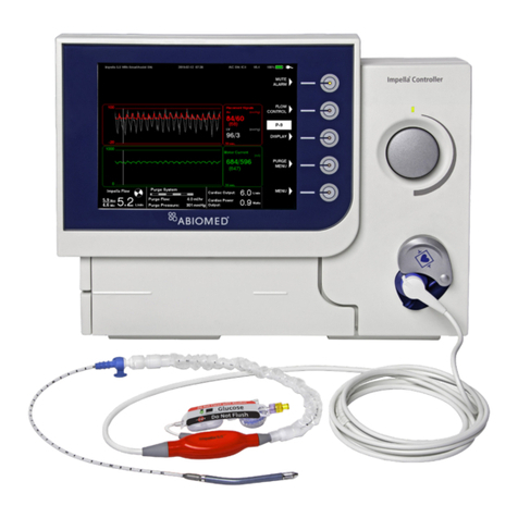
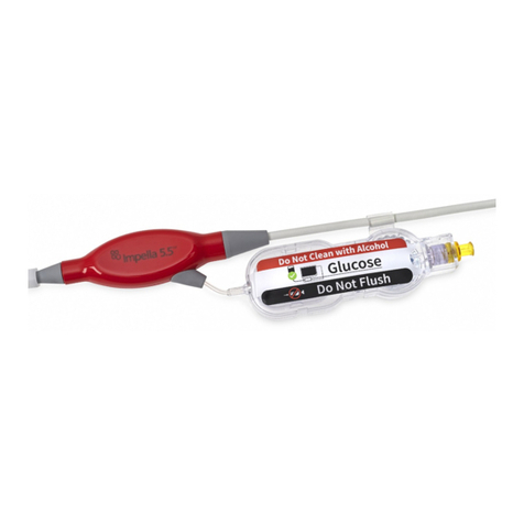
Abiomed Impella LD User manual

USER MANUAL
GEBRAUCHSANWEISUNG
MANUAL DEL USUARIO
MANUALE D'USO
MANUEL D'UTILISATION
ANVÄNDARHANDBOK
GEBRUIKERSHANDLEIDING
BRUGERVEJLEDNING
BRUKERMANUAL
UŽIVATELSKÁ PŘÍRUČKA
INSTRUKCJA OBSŁUGI
KÄYTTÖOHJE
MANUAL DO UTILIZADOR
Impella LD®
Circulatory Support System

TABLE OF CONTENTS
English..................................................................................................... 1
Deutsch ................................................................................................... 15
Español.................................................................................................... 29
Italiano .................................................................................................... 43
Français ................................................................................................... 57
Svenska.................................................................................................... 71
Dansk ...................................................................................................... 85
Nederlands .............................................................................................. 99
Norsk....................................................................................................... 113
Čeština .................................................................................................... 125
Polski....................................................................................................... 137
Suomi ...................................................................................................... 151
Português ................................................................................................ 163

1
Impella LD®Circulatory Support System
INTENDED AUDIENCE
This manual is intended for use by cardiologists, surgeons, nurses, perfusionists, and cardiac catheterization lab technicians who have been trained in the use
of the Impella LD®Circulatory Support System.
CAUTIONS
Cautions indicate situations in which equipment may malfunction, be
damaged, or cease to operate. The light gray symbol appears before
caution messages.
Handle with care. The Impella LD®Catheter can be damaged during
removal from packaging, preparation, insertion, and removal. Do NOT
bend, pull, or place excess pressure on the catheter or mechanical
components at any time.
Patients with aortic stenosis or other abnormal aortic valve performance
may be compromised by the use of the Impella LD Catheter. Patients
with aortic valve disease should be observed for aortic insufficiency.
Physicians should exercise special care when inserting the Impella LD
Catheter in patients with known or suspected unrepaired abdominal
aortic aneurysm or significant descending thoracic aortic aneurysm or
dissection of the ascending, transverse, or descending aorta.
An incision larger than 6 mm may allow the front plug to advance into
the aorta.
Use only original accessories and replacement parts supplied by
Abiomed.
Do NOT use damaged or contaminated connector cables.
When replacing the purge cassette, the replacement process must be
completed within 90 seconds. The Impella LD Catheter may be damaged
if replacement takes longer than 90 seconds.
Do NOT kink or clamp any part of the Impella LD Catheter.
Have a backup Automated Impella Controller, purge cassette, connector
cable, and Impella LD Catheter available in the unlikely event of a device
failure.
Operation of the system without heparin in the purge solution has not
been tested. In the event that a patient is intolerant to heparin, due to
heparin-induced thrombocytopenia or bleeding, physicians should use
their clinical judgment to assess the risks versus benefits of operating
the Impella®System without heparin. If it is in the best interest of the
patient to operate the system without heparin, the dextrose solution
is still required, and physicians should consider systemic delivery of an
alternative anticoagulant. Do NOT add any alternative anticoagulant
(such as a direct thrombin inhibitor) to the purge fluid. The Impella®
Catheter has not been tested with any alternative anticoagulants in the
purge solution.
Do NOT insert the repositioning sheath into the peel-away sheath
during catheter insertion; slide the repositioning sheath towards the red
pump handle prior to inserting the device.
Never remove the guidewire when increased resistance is met.
Determine the cause of resistance using fluoroscopy and verify the
repositioning sheath is not inserted into the peal-away sheath.
In patients with transcatheter aortic valves position the Impella system
carefully to avoid interaction with the TAV prosthesis. In this situation,
avoid repositioning while the device is running; turn the device to
P-0 during repositioning or any movement that could bring the outlet
windows into proximity to the valve stent structures. If there is low
flow observed in a patient implanted with a transcatheter aortic valve
prosthesis, consider damage of the impeller and replace the Impella
pump as soon as possible.
WARNINGS
Warnings alert you to situations that can cause death or serious injury. The
dark gray symbol appears before warning messages.
Use of the Impella System by trained and experienced practitioners has
been associated with improved outcomes. Consequently, the first use
of Impella should be preceded by the completion of a contemporary
Abiomed Impella training program and include on-site proctoring during
the first use by Abiomed clinical support personnel certified in the use of
Impella.
Avoid manual compression of the inlet, outlet, or sensor areas of the
cannula assembly.
The sterile components of the Impella LD System can be used only if the
sterilization indicators show that the contents have been sterilized, the
packaging is not damaged, and the expiration date has not elapsed.
Do NOT resterilize or reuse the Impella LD Catheter. It is a disposable
device and is intended for single use only. Reuse, reprocessing, or
resterilization may compromise the structural integrity of the catheter
and/or lead to catheter failure which, in turn, may result in patient injury,
illness, or death.
Retrograde flow will occur across the aortic valve if the Impella LD
Catheter is set at P-level P-0.
Do NOT use saline in the purge system.
Do NOT use alcohol-based fluids for lubrication.
Do NOT use an Impella LD System if any part of the system is damaged.
To prevent the risk of explosion, do NOT operate the Impella LD System
near flammable anesthetics.
If at any time during the course of support with the Impella LD
Catheter, the Automated Impella Controller alarms “Purge Pressure
Low” or “Purge System Open,” follow the instructions presented in the
Automated Impella Controller manual.
Do NOT subject a patient who has been implanted with an
Impella LD Catheter to magnetic resonance imaging (MRI).
The strong magnetic energy produced by an MRI machine may
cause the Impella LD System components to stop working and
result in injuries to the patient. An MRI may also damage the
electronics of the Impella LD System.
Cardiopulmonary support (CPR) should be initiated immediately per
hospital protocol if indicated for any patient supported with the Impella
LD Catheter. When initiating CPR, reduce the Impella LD Catheter flow
rate. When cardiac function has been restored, return flow rate to the
previous level and assess the placement signal on the controller.
During defibrillation, do NOT touch the Impella LD Catheter, cables, or
Automated Impella Controller.
ENGLISH

User Manual
2
INTENDED USE (EU)
INTENDED USE IN THE EUROPEAN UNION
The Impella LD®(intracardiac pump for supporting the left ventricle) is
intended for clinical use in cardiology and in cardiac surgery for up to 10 days
for the following indications, as well as others:
• The Impella LD is a cardiovascular support system for patients with
reduced left ventricular function, eg, post-cardiotomy, low output
syndrome, cardiogenic shock after acute myocardial infarction
• The Impella LD may also be used as a cardiovascular support system
during coronary bypass surgery on the beating heart, particularly in
patients with limited preoperative ejection fraction with a high risk of
postoperative low output syndrome
CONTRAINDICATIONS (EU)
CONTRAINDICATIONS IN THE EUROPEAN UNION
• Mechanical aortic valves, severe aortic valvular stenosis or valvular
regurgitation
• Hematological disorder causing fragility of the blood cells or hemolysis
• Hypertrophic obstructive cardiomyopathy (HOCM)
• Aneurysm or necrotomy or severe anomaly of the ascending aorta
and/or the aortic arch
• Mural thrombus in the left ventricle
• Ventricular septal defect (VSD) after myocardial infarction
• Anatomic conditions precluding insertion of the pump
• Other illnesses or therapy requirements precluding use of the pump
• Severe peripheral arterial occlusion disease (PAOD) is a relative
contraindication
POSSIBLE COMPLICATIONS (EU)
There are risks of complications with every procedure using a blood pump.
These include among others:
• Hemolysis
• Bleeding
• Immune reaction
• Embolism, thrombosis
• Vascular injury through
to angionecrotomy
• Positioning problems
• Infection and septicemia
• Dislocation of the pump
• Cardiovalvular injuries due to extreme
movement of the suction cannula in
relation to the cardiac valve or as a result of
attachment by suction of the pump to the
valve system following incorrect positioning
• Endocardiac injuries as a result of
attachment of the pump due to suction
• Pump failure, loss of pump components
following a defect
• Patient dependency on the pump after use
for support
OVERVIEW
When properly positioned, the Impella LD®Catheter delivers blood from
the inlet area, which sits inside the left ventricle, through the cannula to
the outlet opening in the ascending aorta. Physicians and device operators
monitor the correct positioning and functioning of the Impella LD Catheter
on the display screen of the Automated Impella Controller. This section
describes the components of the Impella Catheter and the Automated Impella
Controller, as well as the accessory components.
REUSABLE SYSTEM COMPONENTS
The Impella LD System consists of the following reusable components:
• Automated Impella Controller—provides the user interface, alarm
indications, and portable battery
• Automated Impella Controller cart—for easy transport of the
Automated Impella Controller
SINGLE-USE SYSTEM COMPONENTS
The Impella LD System also includes the following single-use components:
• Impella LD Catheter
• Purge cassette
• Incision template
• Connector cable
SYSTEM CONFIGURATION
Glucose
Solution
Automated Impella Controller
Purge Cassette
Impella LD Catheter
G5
Connector Cable
Connect Purge Tubing Directly
to Impella Catheter
Disconnect Y Connector from Purge Tubing
IMPELLA LD®CATHETER
The Impella LD Catheter is an intravascular microaxial blood pump that
delivers up to 5.0 liters of blood per minute from the left ventricle into the
aorta.
Infusion Filter
Pressure
Reservoir
Cannula
Inlet Area
Motor
Housing
Silicone
Plugs
Differential
Pressure
Sensor
Outlet Area
Red
Impella®
Plug
Check
Valve
Catheter Shaft
DIFFERENTIAL PRESSURE SENSOR
The Impella LD Catheter has an electronic differential pressure sensor located
at the proximal end of the 21 Fr cannula. The purpose of the pressure sensor
is to generate the placement signal, which is used by operators and the
controller to monitor the position of the Impella LD cannula relative to the
aortic valve.
The pressure sensor is a flexible membrane integrated into the cannula. One side
of the sensor is exposed to the blood pressure on the outside of the cannula and
the other side is exposed to the pressure of the blood inside of the cannula. The
sensor generates an electrical signal proportional to the difference between the
pressure outside the cannula and the pressure inside. This signal is displayed on
the Automated Impella Controller as the placement signal.
2

3
Impella LD®Circulatory Support System
Aortic Valve
Membrane
Sensor
Differential
Pressure Sensor
Aortic Pressure
Flow to
Aorta
Flow from
Ventricle
Cannula
Ventricular
Pressure
The pressure sensor membrane flexes when the pressure on one side is
different from the pressure on the other side, and the electrical properties
of the membrane change when it flexes. This allows the sensor to generate
an electrical signal proportional to how much the membrane is flexed, and
thus proportional to the difference between the pressure on the outside of
the cannula and the pressure inside. When the Impella LD Catheter is placed
in the correct position across the aortic valve, the top (outer surface) of the
sensor is exposed to the aortic pressure and the bottom (inner surface) of the
sensor is exposed to the ventricular pressure. Therefore, the placement signal
is approximately equal to the difference between the aortic pressure and the
ventricular pressure.
Blood Pressure (mmHg)
Time
Systole
Diastole
120
0
80
Pressure difference (P
Differencial
)
Aortic pressure
PDifferential = PAO - PLV
Left ventricular pressure (PLV )
Aortic pressure (P
AO
)
Pressure
difference
Left ventricular
pressure
When the Impella LD Catheter is correctly positioned across the aortic valve,
the changes in pressure associated with the cardiac cycle result in a pulsatile
placement signal. During diastole, the large pressure difference between the
aorta and the left ventricle creates a large electrical signal. Then at the peak
of systole, when the aortic valve opens, the pressure difference between the
aorta and the left ventricle—and thus the electrical signal—is zero.
Thus, the continual pressure changes associated with the cardiac cycle
produce the pulsatile (up and down) waveform seen on the Automated
Impella Controller display.
When the Impella LD®Catheter is not properly placed across the aortic valve,
or when it is fully in the aorta or fully in the ventricle, the pressures outside
and inside the cannula are the same throughout the cardiac cycle. As a result,
the pressure on either side of the sensor membrane is the same, resulting in a
flat placement signal.
PURGE CASSETTE
Do not use saline in the purge system.
The purge cassette delivers rinsing fluid to the Impella LD Catheter. The purge
fluid (typically 5% glucose solution in water with Heparin) flows from the
purge cassette through the catheter to the microaxial blood pump to prevent
blood from entering the motor. When the purge cassette is properly installed
in the Automated Impella Controller, the Abiomed® logo is upright and
facing you.
Note: If included, disconnect and discard the Y Connector from the purge
tubing when setting up the Impella LD System and connect the yellow luer
on the end of the purge tubing directly to the yellow luer on the Impella LD
Catheter
ENGLISH

User Manual
ACCESSORIES
Component Description
The white connector cable connects the
Impella LD®Catheter to the Automated
Impella Controller. Clips on the cable are
used to secure the purge tubing to the
cable.
• The socket at the gray end of the cable
connects to the red Impella®Catheter
plug.
• The white plug at the opposite end
of the cable is inserted into the blue
catheter plug on the front of the
Automated Impella Controller.
The incision template is used to assist
in correct placement of the Impella LD
Catheter during implantation by indicating
the correct location for the incision in the
ascending aorta.
Hospital Provided:
Dextrose solution (typically 5% glucose in
water with 50 IU/mL of heparin) is used
as the purge fluid through the Impella LD
Catheter.
The Automated Impella Controller cart
holds the Automated Impella Controller.
The cart has wheels for easy transport of
the controller and a storage basket. (For
more information, including assembly
instructions, refer to the Automated
Impella Controller cart instructions for
use.)
STARTUP
SUPPLIES NEEDED
• Automated Impella Controller
• Impella LD®Catheter and accessories
• 500 cc bag of glucose solution in water for purge solution (5%
recommended; 5% to 20% acceptable) with 50 IU heparin/mL
• 10 mm diameter x 15 cm length Dacron®vascular graft
Note: If the purge solution is supplied in bottles, open the vent on the purge
fluid spike and follow the same procedure as if supplied in bags.
CASE START
If you miss a step in the process of setting up the Impella Catheter, or if
you exceed the amount of time allowed to complete a step, the Automated
Impella Controller will display additional instruction screens for continuing the
setup process for some steps. For the steps discussed below, all shaded steps
require sterile technique
CASE START
1. Press the START NEW CASE soft button from the startup screen or
plug in a new Impella catheter. “Case Start” can also be selected by
pressing the MENU soft key.
2. The controller displays the screen below.
INSERT PURGE CASSETTE
1. Open the purge cassette package onto the sterile field.
2. If included, remove and discard the Y connector. Secure the yellow
luer connector on the purge tubing to the sterile field.
3. Pass the purge cassette and spike off the sterile field.
4. Spike the glucose bag/bottle.
5. Press the NEXT soft button to continue.
6. Open the purge cassette door by pressing the release on the left side
of the controller. Insert the purge cassette into the Automated Impella
Controller.
7. Insert the purge cassette into the molded compartment on the front of
the controller. Follow the diagram on the inside of the purge cassette
door for proper placement.
8. Slide the purge disc into the slot to the right of the purge cassette
until it snaps into place. The controller will automatically begin
priming the purge cassette.
Note: The instructions for inserting the purge disc appear if the disc is
not snapped into place within 3 seconds of inserting the purge disc.
9. Extend the purge tubing and close the purge cassette door. There is
sufficient room around the edges of the purge cassette door so that it
will not pinch the purge tubing as it exits.
10. The controller automatically begins priming the purge cassette after it
is inserted. The progress bar marks the progress of the purge cassette
priming.
4

5
Impella LD®Circulatory Support System
CONNECT THE IMPELLA®CATHETER
1. Remove the Impella Catheter from its package using sterile technique
and inspect the catheter, including its connector, for damage.
2. Remove the white connector cable from its package using sterile
technique.
3. Inspect the cable for damage, including damage to the connector pins
at the controller end.
4. Secure the grey end of the cable to the sterile field.
5. Pass the sterile connector cable from the Impella Catheter off the
sterile field.
6. Line up the notch on the connector cable with the notch in the blue
catheter plug on the front of the Automated Impella Controller and
plug the cable into the controller.
7. Insert the catheter plug into the connector cable socket (grey end).
The tab and the slot must be aligned during connection.
Connector
Cable Socket
(grey end)
Catheter Plug
8. Pull back on the connection to make sure that the plug has snapped
into place.
9. Snap the purge clip (located on the pressure reservoir of the clear
sidearm) to the connector cable.
Note: Snapping the purge clip on the pressure reservoir to the
connector cable is important to prevent the tube from kinking.
10. If included and you have not already done so, remove and discard
the Y connector with the red and yellow luers from the purge tubing.
Connect and tighten the luers on the end of the purge tubing to the
Impella Catheter sidearms.
11. When the controller detects that the luer is connected, it automatically
begins priming the purge lumen.
ENTER PURGE FLUID DATA
1. After confirming that fluid is exiting the Impella Catheter, enter the
purge fluid information.
2. To select the default values displayed on the screen, press the ACCEPT
soft button. This will select those values and automatically advance to
the next screen. Note: The default purge fluid values will be the purge
fluid values from the last Case Start performed on the Automated
Impella Controller.
3. To change the purge fluid information, press the EDIT soft button,
scroll to the appropriate item and push the selector knob to select it
or use the white arrow soft buttons. Then scroll through the values
and push the selector knob to make a new selection. Press the DONE
button to finish editing. The controller will use the default values if no
other selections are made.
• Purge fluid can be set to 50 mL, 100 mL, 250 mL, 500 mL, or 1000
mL.
• Glucose concentration can be set to 5%, 10% or 20%.
• Heparin concentration can be set to 0 IU/ml, 5 IU/ml, 6.25 IU/ml,
10 IU/ml, 12.5 IU/ml, 20 IU/ml, 25 IU/ml, 40 IU/ml, 50 IU/ml.
ENGLISH

User Manual
INSERTING AND STARTING THE
IMPELLA LD®CATHETER
NOTE – Proper surgical procedures and techniques are the
responsibility of the medical professional. The described
procedure is furnished for information purposes only. Each
physician must evaluate the appropriateness of the procedure
based on his or her medical training and experience, the type
of procedure, and the type of systems used. When the Impella
LD Catheter is used in the OR as part of open heart surgery,
manipulation may be performed only through the 9 Fr steering
catheter. Direct manipulation of the catheter assembly through
the aorta or ventricle may result in serious damage to the Impella
LD Catheter and serious injury to the patient.
The Impella LD Catheter is surgically inserted when there is access to the
ascending aorta through a sternotomy or thoracotomy. Transesophageal
echocardiography (TEE) is required to guide placement.
PREPARATION
1. Using the supplied sterile incision template for positioning (see
sidebar), place a sidebiter clamp on the aorta at least 7 cm above the
valve plane.
Note: An incision too close to the aortic valve annulus could result in
the catheter outlet area in the graft rather than the aorta.
2. Make an incision (or punch) no larger than 6 mm at the insertion site
on the ascending aorta.
Note: The incision must be ≤ 6 mm in length to prevent the front
silicone plug from advancing into the aorta through the incision.
3. Attach the Dacron®vascular graft (10 mm x 15 cm) to the aorta using the
standard end-to-side anastomosis.
4. Administer heparin and achieve ACT of at least 250 seconds.
5. When the anastomosis is complete, place a clamp at the distal end of
the graft and then release the proximal clamp at the base of the graft.
Examine the suture line for leaks and reclamp the graft at the base.
6. Moisten the Impella LD Catheter and push both silicone plugs up
against the motor housing.
Note: There should be no movement of the front silicone plug within
the graft; however, the catheter shaft should move without resistance
within the plug. When securing the front silicone plug to the graft, do
not penetrate the silicone plug too deeply as this could cause damage
to the Impella LD Catheter.
Rear
Sillicone
Plug
Front
Sillicone
Plug
POSITIONING AND STARTING THE IMPELLA LD CATHETER
Retrograde flow will occur across the aortic valve if the Impella LD
Catheter is set at P-level P-0.
1. Confirm purge fluid is exiting the Impella Catheter.
2. With the graft clamped at the base, place the Impella LD Catheter into
the open end of the graft up to the level of the rear plug.
3. When the catheter is in position, secure a tourniquet around the rear
silicone plug. Tighten the tourniquet sufficiently to control bleeding
around the rear plug while still allowing the catheter to slide through the
plug.
4. Release the clamp and advance the Impella LD Catheter into the aorta.
5. If the patient is on cardiopulmonary bypass (CPB), allow the heart to
fill by restricting the return flow to the bypass machine and reducing
CPB flow to a minimum setting, as long as acceptable physiologic
systemic flow is maintained.
Note: Low pulsatility may lead to catheter position unknown alarms
in conjunction with CPB.
6. As soon as the motor housing has passed into the aorta, use a
ligature to loosely secure the front silicone plug flush to the graft. The
silicone plug should be in the most proximal portion of the graft.
7. While the catheter is being advanced in the aorta, the initial
placement signal is flat. The inlet area of the catheter has not passed
the aortic valve. Do not allow the front plug to advance beyond the
base of the graft.
8. To aid in passing the catheter through the aortic valve, apply slight
pressure to the posterior aspect of the aortic valve to produce
temporary aortic insufficiency.
9. Gently advance the catheter forward until a pulsatile waveform is
present on the placement signal screen. This signal is generated when
the inlet area of the catheter crosses the aortic valve.
10. Confirm that the controller displays a pulsatile waveform and the
tip of the inlet area of the Impella LD®Catheter is 3.5 cm below the
aortic valve. Confirm catheter position using TEE.
Note: When the Impella Catheter is not correctly placed, there is no
effective unloading of the ventricle. The patient may not be benefiting
from the flow rate shown on the controller.
11. Press START IMPELLA soft button to open the P-level menu.
12. Turn the selector knob to increase the P-level from P-0 to P-2.
13. Press the selector knob to select the new P-level.
14. The catheter operation icon in the lower left corner of the screen
begins rotating when the Impella LD Catheter begins to operate.
6

7
Impella LD®Circulatory Support System
15. Press the FLOW CONTROL soft button to increase the P-level to P-9 to
confirm correct and stable placement. Verify placement with TEE and the
placement signal screen. Reposition the catheter as necessary.
Note: When the flow rate is increased to maximum flow, the Impella
LD Catheter has a tendency to be drawn into the ventricle. Check
positioning at maximum flow to ensure proper placement throughout
the P-level setting range
16. Position the front silicone plug as close as possible above the aorta.
Secure the silicone plug to the graft using a penetrating suture
ligature.
Note: When securing the silicone plug to the graft, ensure that the
penetrating suture does NOT go all the way through the silicone plug
and damage the Impella LD Catheter inside the plug.
Transesophageal echocardiogram (TEE)
illustration showing correct Impella LD®Catheter position
Impella LD®
Catheter
inlet area Impella LD®
Catheter
outlet area
RV
LV
LA
Aortic valve
Penetrating
Suture
Ligature
Rear Silicone Plug
Front Silicone Plug
Transesophageal echocardiogram (TEE)
illustration showing correct Impella LD®Catheter position
Impella LD®
Catheter
inlet area Impella LD®
Catheter
outlet area
RV
LV
LA
Aortic valve
Penetrating
Suture
Ligature
Rear Silicone Plug
Front Silicone Plug
17. Clear the vascular graft of excess blood and resecure the rear silicone
plug to the end of the graft.
18. After achieving correct and stable placement, decrease the P-level to the
desired level for support.
Note: After implantation of the catheter (and until explant), ACT should
be maintained at 160 to 180 seconds.
19. Select the lowest P-level that will enable you to achieve the flow rate
necessary for patient support. You can select one of ten P-levels (P-0 to
P-9) for the Impella LD Catheter
P-LEVELS
You can select one of ten P-levels (P-0 to P-9) for the Impella LD®Catheter.
Select the lowest P-level that will enable you to achieve the flow rate
necessary for patient support.
P-Level *Flow Rate (L/min)
P-0 0.0
P-1 0.0 – 1.4
P-2 0.5 – 2.6
P-3 0.5 – 3.1
P-4 0.9 – 3.4
P-5 1.4 – 3.7
P-6 1.8 – 4.0
P-7 2.6 – 4.4
P-8 3.4 – 4.7
P-9 4.2 – 5.3
*Flow rate can vary due to suction or incorrect positioning.
PURGE CASSETTE PROCEDURES
CHANGE CASSETTE & BAG
Follow these steps to change both the purge cassette and purge fluid:
1. Press PURGE MENU and select “Change Cassette and Bag” from the
menu.
2. Select START to begin the cassette and fluid change process.
3. When prompted by the controller, disconnect the luer from the Impella
catheter. Note on Connecting Purge Tubing to the Catheter: If
included, remove and discard the y-connector and connect the yellow
luer on the purge tubing directly to the yellow check valve on the
Impella Catheter.
4. Open the Purge Cassette door by pressing the button on the left side
of the console. Remove and discard the old cassette and purge fluid
bag.
5. Open the new Purge Cassette. Spike the new purge fluid bag with the
new purge cassette tubing. Select NEXT to continue.
6. Insert the new purge cassette into the controller. Be sure to slide the
purge disc into place and extend the purge tubing through the gap in
the purge cassette door when you close the door.
ENGLISH

User Manual
7. Confirm the luer is disconnected. Press NEXT to proceed to prime the
purge cassette. Once the priming is complete, you are prompted to
connect the purge tubing to the Impella LD®Catheter.
8. Update the purge fluid information.
a. To select the default purge fluid values displayed on the
screen, select CONFIRM.
b. To change the purge fluid information, select EDIT. Then use
the soft keys to navigate selections and edit values. Select
DONE to complete editing.
9. When Steps 1 through 8 are complete, connect the luer from the new
purge cassette to the Impella catheter.
CHANGE PURGE FLUID BAG
Note on Purge Solution Bottles: If the purge solution is supplied in
bottles, open the vent on the purge fluid spike and follow the same procedure
as if supplied in bags.
Perform the following steps to change only the purge fluid.
1. Press PURGE MENU and select “Change Purge Fluid Bag.”
2. Select START to begin the purge fluid change process.
3. When prompted by the controller, remove the old purge bag and
replace by spiking the new purge fluid bag. Select NEXT to advance
to the next step.
4. Update the purge fluid information.
a. To select the default purge fluid values displayed on the
screen, select CONFIRM.
b. To change the purge fluid information, select EDIT. Then use
the soft keys to navigate selections and edit values. Select
DONE to complete editing.
5. When prompted by the controller, disconnect the luer from the Impella
Catheter. The controller will automatically prime the tubing, which will
flush the fluid from the last bag out of the purge cassette tubing.
a. To skip the flush, select SKIP PRIME.
Note: The instructions to disconnect the luer and to automatically
prime the tubing only occurs if the user changed the purge fluid
dextrose or heparin concentrations.
6. When prompted by the controller, connect the yellow luer from the
purge cassette to the Impella catheter.
Note on Priming Purge Cassette and Disconnecting Luers:
The system only prompts you to remove luers to prime and flush tubing
if the heparin or dextrose concentrations were changed or air was
detected. You can only select SKIP PRIME if no air was detected.
PATIENT WEANING
Weaning the patient from the Impella LD Catheter is at the discretion of the
physician. Removal of the Impella Catheter must be completed with care to
avoid damage to the catheter assembly. Do NOT attempt to remove the Impella
Catheter through the repositioning sheath. The Impella Catheter will not pass
through the repositioning sheath.
The following weaning protocols are provided as guidance only.
RAPID WEANING
1. Initiate rapid weaning by decreasing catheter P-level in 2-level steps at
intervals of several minutes (for example, P-6 to P-4 to P-2). Do
NOT
decrease P-level to below P-2 until just before removing the catheter
from the ventricle.
2. When the P-level has been reduced to P-2, maintain the patient on
P-2 support for
at least 10 minutes
before discontinuing circulatory
support.
3. If the patient’s hemodynamics remain stable, follow the instructions in
the next section for removing the Impella LD catheter.
SLOW WEANING
1. Initiate slow weaning by decreasing catheter P-level in 2-level steps
over time as cardiac function allows (for example, P-6 to P-4 to P-2).
Do
NOT
decrease P-level to below P-2 until just before removing the
catheter from the ventricle.
2. When the P-level has been reduced to P-2, maintain the patient on
P-2 support until the patient’s hemodynamics remain stable
before
discontinuing circulatory support.
3. If the patient’s hemodynamics remain stable, follow the instructions in
the next section for removing the Impella LD catheter.
REMOVING THE IMPELLA LD®CATHETER
PREPARATION FOR REMOVAL
1. Gain exposure and clear access to the ascending aorta insertion site,
the Dacron®vascular graft, and the sites at which the silicone plugs
are secured to the graft.
2. Complete weaning procedure at P-level P-2 as described previously.
3. Undo the penetrating suture from the
front
silicone plug and remove
the suture entirely.
4. Remove the ligature from the
rear
silicone plug and remove the plug
from the end of the vascular graft.
5. Maintaining distal control digitally, remove the final circumferential
ligature from the
front
silicone plug.
6. Allow controlled bleed-back through the graft to clear any residual
thrombus from the lumen of the graft.
PULLING THE IMPELLA LD CATHETER INTO THE ASCENDING
AORTA
Perform the following steps under the guidance of transesophageal
echocardiography (TEE).
1. Immediately prior to pulling the Impella LD Catheter across the aortic
valve, reduce the P-level to P-1.
2. Carefully pull the Impella LD Catheter back through the aortic valve
and into the ascending aorta. Depending on the level of the insertion
site, a portion of the catheter may be pulled through the aortotomy
and into the vascular graft.
3. Immediately reduce the P-level to P-0 after the Impella LD Catheter
crosses the aortic valve and enters the ascending aorta. The Impella
LD Catheter should only be removed when the P-level is set to P-0.
4. Gently pull the Impella LD Catheter completely through the aortotomy
and into the vascular graft.
5. Close the graft.
VASCULAR GRAFT CLOSURE
When closing the vascular graft, consider individual patient characteristics
and select the strategy most consistent with an optimal clinical result. The
entire vascular graft can be removed if indicated, but it is not mandatory to
do so. Graft closure options include:
• Amputating the vascular graft and sewing the small end-to-side
remnant closed by hand
• Using a vascular stapler to close the graft near the surface of the
aorta
• Removing the complete graft with local patch closure, if necessary
8

9
Impella LD®Circulatory Support System
PRESSURE SENSOR DRIFT AND
PLACEMENT SIGNAL NOT RELIABLE
SENSOR
MANUALLY ZEROING THE DIFFERENTIAL PRESSURE SENSOR
The electrical signal produced by the differential pressure sensor may drift
over time. This drifting is normal behavior and is characterized by an upward
or downward shift in the placement signal on the controller display. The
amplitude (peak-to-trough, or maximum to minimum) of the waveform will
not change. In addition, when sensor drifting occurs, the displayed flow rate
may not match the P-level.
If you observe that the placement waveform has shifted up or down on the
display, or the expected flow does not match the current P-level setting, zero
the differential pressure sensor by performing the following steps:
1. Press the MENU key and select “Start Manual Zero.”
2. Press OK to adjust flow level.
3. The controller displays “Wait until the new flow level is reached” and
then “Offset calculation is in process.”
4. Select OK to accept the new setting when the controller displays the
“Placement Signal Offset Adjust finished” message.
5. The Impella®will automatically be reset to the previous P-level.
ZEROING THE DIFFERENTIAL PRESSURE SENSOR WHEN THE
IMPELLA LD®CATHETER IS RUNNING
The controller software contains a data table listing the expected differential
pressure for a given motor current when the motor speed is set to a specific
value. To zero the differential pressure sensor while the Impella LD Catheter is
running, the software sets the motor speed and measures the motor current.
Using the data table, the software determines what the measured differential
pressure should be, then adjusts the signal from the differential pressure
sensor so that it matches the expected value.
PLACEMENT SIGNAL NOT RELIABLE AND EFFECTS ON FLOW
CALCULATIONS
If the pressure sensor fails, the controller can no longer calculate the flow
rate. The controller displays a “Placement Signal Not Reliable” alarm. The
placement screen displays a table with estimated flows and corresponding
MAPs in the bottom-left corner of the display. The Home screen displays
a yellow question mark over the heart icon and “Placement Monitoring
Suspended.” To silence this alarm, go to MENU and select SETTINGS/
SERVICE.
PLACEMENT SIGNAL NOT RELIABLE AND EFFECTS ON
POSITION CONTROL
If the pressure sensor fails, placement monitoring is switched off because
it is not possible to display the position of the catheter. In this case, the
motor current signal or imaging procedures can be used for position control.
As long as the motor current signal is pulsatile, the Impella LD Catheter is
correctly positioned across the valve. This signal must be monitored closely
because the catheter can become dislodged (displaced) when moving the
patient or changing the patient’s position. Therefore, if patient hemodynamics
change—for example, if arterial pressure falls or there are signs of left
ventricular failure—check the correct positioning of the catheter using
imaging procedures (eg, TEE) and the motor current signal.
SUCTION DETECTION DURING SENSOR DRIFT OR
PLACEMENT SIGNAL NOT RELIABLE
If sensor drift occurs or the pressure sensor fails, the controller can no longer
detect suction. The effectiveness of Impella LD Catheter support can only
be assessed by monitoring patient hemodynamics, cardiac imaging, and the
Impella LD Catheter motor current.
Signs of suction include:
• A drop in the patient’s arterial pressure
• Decreased output, if a cardiac monitor is in place
• Dampened or flat motor current waveforms
If imaging reveals that the suction is caused by the catheter inlet area in close
proximity to the intraventricular wall, reposition the catheter. If hemodynamic
parameters, such as low aortic pressure or high pulmonary artery pressure,
indicate suction caused by inadequate filling volume, reduce performance level.
OPERATING THE IMPELLA LD®CATHETER
WITHOUT HEPARIN IN THE PURGE
SOLUTION
The Impella LD Catheter is designed to be operated with a purge solution
that contains heparin. Operation of the system without heparin in the
purge solution has not been tested. In the event that a patient is intolerant
to heparin, due to heparin-induced thrombocytopenia (HIT) or bleeding,
physicians should use their clinical judgment to assess the risks versus
benefits of operating the Impella®System without heparin.
If it is in the best interest of the patient to operate the system without
heparin, the dextrose solution is still required, and physicians should consider
systemic delivery
of an alternative anticoagulant. DO NOT add any alternative
anticoagulant (such as a direct thrombin inhibitor) to the purge fluid. The
Impella LD Catheter has not been tested with any alternative anticoagulants
in the purge solution.
OPERATING THE IMPELLA LD CATHETER
IN ELECTROMAGNETIC FIELDS
The Impella LD Catheter contains a permanent magnet motor that emits an
electromagnetic field. This field may produce electromagnetic interference
with other equipment. In addition, other equipment that emits a strong
electromagnetic field may affect the operation of the Impella LD Catheter
motor.
ELECTROANATOMIC MAPPING (EAM) SYSTEMS
Examples of EAM Systems
• CARTO®3 System and
• CARTO®XP Navigation System (Biosense Webster, Inc.)
The electromagnetic field emitted by the Impella LD Catheter may produce
interference with the magnetic location detection component of the
electroanatomic mapping (EAM) system, particularly when the mapping
catheter is close to the Impella LD Catheter motor. For example, mapping
in the right or left ventricular outflow tracts places the mapping catheter in
close proximity to the Impella LD Catheter motor in the ascending aorta.
Electromagnetic interference may appear as:
• Instability in the displayed location of the mapping catheter
• Magnetic interference errors generated by the electroanatomic
mapping system
ENGLISH

User Manual
If you suspect interference, follow the troubleshooting steps below.
Observation Actions
Interference with the
magnetic location
detection component
of the EAM system
1. Check for and address other sources of interference.
2. Reposition the Impella®Catheter to ensure that the
Impella®motor is at least 3 cm from the sensors in the
mapping catheter; however do NOT pull the inlet area
out of the left ventricle.
3. Ensure that the Impella®Catheter is operating at
P-1–P-5 or P-7, as these P-levels cause the least
interference.
MAGNETIC NAVIGATION SYSTEMS (MNS)
Example of MNS
• Stereotaxis Niobe®Magnetic Navigation System (Stereotaxis)
When initiating Impella LD Catheter support in the presence of a magnetic
navigation system (MNS), follow the steps below:
1. Insert the Impella LD Catheter following the steps outlined in this
manual.
2. Place the MNS magnets in the “Reduced” or “Stowed” position.
3. Start the Impella LD Catheter in the manner described in this manual.
Increase P-level to at least P-5.
4. Place the MNS magnets in the “Navigate” position and proceed with
magnetic navigation.
Keep operating the Impella LD Catheter at a P-level of at least P-5 when the
MNS magnets are in the “Navigate” position. If the P-level falls below P-5,
the Impella LD Catheter may stop running. To resume operation, follow the
steps in the table below.
During magnetic navigation of the mapping catheter, the motor current
of the Impella LD Catheter may temporarily increase to the point that the
catheter stops running.
When the MNS magnets are in the “Navigate” position, the displayed
Impella LD Catheter flow may be artificially elevated. To accurately assess the
flow rate, note the displayed flow when the magnets are in the “Stowed”
position.
Observation Actions
Unable to start
Impella LD®
or
Impella LD stops
running
1. Place the MNS magnets in the “Reduced” position and
attempt to start the Impella LD®Catheter.
2. If the Impella LD Catheter does NOT start with the
magnets in the “Reduced” position, place the magnets in
the “Stowed” position and start the Impella LD Catheter.
3. Increase the Impella LD Catheter P-level to P-5 or higher.
4. Place the MNS magnets in the “Navigate” position and
proceed with magnetic navigation.
MNS magnets:
“Navigate”
Displayed flow
seems too high
or
MNS magnets:
“Stowed”
Displayed flow
drops
The Impella LD Catheter displayed flow will be artificially
elevated when the MNS magnets are in the “Navigate”
position.
The displayed flow will be accurate when the MNS magnets
are in the “Stowed” position.
ALARMS OVERVIEW
The Automated Impella Controller monitors various functions to determine
whether specific operational parameters are within expected limits. When
a parameter goes outside of its specified limits, the controller sounds an
alarm tone and displays an alarm message that can be viewed on the display
screen on the front of the controller. The alarm tone indicates the severity
of the alarm. The alarm message on the display screen is color-coded for
severity and provides details on the cause of the alarm and how to resolve
the alarm. After muting an alarm, if another alarm occurs it will only be heard
and displayed if it’s a higher priority alarm that the one that was muted.
For a full list of all Impella alarms, refer to the Automated Impella Controller
Instructions for Use document.
ALARM LEVELS
Alarms are divided into three levels of severity:
• Advisory (white)
• Serious (yellow)
• Critical (red)
Category Description Audible Indicator* Visual Indicator
Advisory Notification 1 beep every 5
minutes Alarm header on white
background
Serious Abnormal
situation.
Prompt action
needed.
3 beeps every 15
seconds Alarm header on yellow
background
Critical High priority.
Immediate
action needed.
10 beeps every 6.7
seconds Alarm header on red
background
* Sound pressure of audible alarm indicators is >80 dBA
MUTE ALARM FUNCTION
Pressing the MUTE ALARM button on the upper right of the Automated
Impella Controller display screen will silence the audible alarm indicator for
2 minutes (for red or yellow alarms) or 5 minutes (for white advisory alarms).
When an alarm is silenced, the words “MUTE ALARM” next to the button
are replaced by the mute alarm indicator, a crossed-out bell icon. The audible
indicator will shut off if an alarm condition is resolved before you press
MUTE ALARM. The visual message, however, will continue to be displayed,
with the alarm header on a gray background, for 20 minutes or until you
press MUTE ALARM. This allows you to identify the alarm that occurred.
10

11
Impella LD®Circulatory Support System
SYMBOLS
Caution; follow instructions for use
Defibrillator-proof type CF equipment
Keep dry
Storage temperature (eg, 10°C to 30°C)
Declares conformity with Directive 93/42/EEC for
medical devices or with Regulation (EU) 2017/745
on medical devices, and with Directive 2011/65/EU
on the restriction of the use of certain hazardous
substances in electrical and electronic equipment
2019-11-06 Date of manufacture (eg, 2019-11-06)
Protect from sunlight
Symbol for lot designation; the manufacturer’s lot
designation must be stated after the LOT symbol
REF 123456 Abiomed part number (eg, part number 123456)
SN 123456 Manufacturer’s serial number (eg, serial number
123456)
Non Sterile! The product is not sterile
YYYY-MM-DD
Use-by date (eg, YYYY-MM-DD)
Do not reuse
Sterilized using ethylene oxide
Medical Device
Glucose
WHITE CONNECTOR CABLE
Length 2.5 m
Service life Single use only
ENGLISH

User Manual
IMPELLA LD®CATHETER PARAMETERS
Speed range 0 to 33,000 rpm
Power consumption Less than 13 W
Voltage Max. 20 V DC
Flow-Maximum 5.0 L/min
Purging the Impella LD®Catheter
Recommended purge fluid
Dextrose concentration
Purge pressure
Purge
5% glucose solution with heparin concentration of 50 IU per mL
5% to 20%
300 to 1100 mmHg
2 to 30 mL/hr
Maximum duration of use
EU and Canada
Reliability
Up to 10 days
91.4% with 80% confidence at 10 days based on chi-squared
test
Classification per DIN EN 60601-1 Protection class I, degree of protection:
CF (Automated Impella Controller and Impella LD Catheter)
Classification per directive 93/42/EEC Class III
Latex free Yes
IMPELLA LD®CATHETER DIMENSIONS
21 Fr9 Fr
7 cm
10 cm
125 cm (min) to 133 cm (max)
DISPOSING OF THE IMPELLA LD CATHETER AND ACCESSORIES (EUROPEAN UNION)
The Impella LD Catheter and connector cable are disposable items that must be disposed of in accordance with hospital regulations for blood contaminated
materials.
The Automated Impella Controller is marked according to Directive 2012/19/EU. Devices sold within the EU can be returned to Abiomed Europe
GmbH for correct disposal.
12

13
Impella LD®Circulatory Support System
ENGLISH

Gebrauchsanweisung
14

15
Impella LD®Kreislaufunterstützungssystem
ZIELGRUPPE
Diese Anleitung ist für Kardiologen, Chirurgen, Pflegekräfte, Kardiotechniker
und Herzkatherisierungs-Labortechniker vorgesehen, die in der Nutzung des
Impella LD®Kreislaufunterstützungssystems geschult sind.
WARNHINWEISE
Warnhinweise zeigen Situationen an, die zu schweren oder tödlichen
Verletzungen führen können. Das dunkelgraue Symbol wird vor
Warnhinweisen angezeigt.
Die Verwendung des Impella®Systems durch geschulte und erfahrene
Ärzte ist mit besseren Ergebnissen verbunden. Daher sollte vor dem
erstmaligen Gebrauch von Impella ein aktuelles Abiomed Impella
Schulungsprogramm absolviert werden. Dieses sollte einen ersten
Vor-Ort-Einsatz umfassen, der durch klinisches, in der Verwendung
des Impella®Systems zertifiziertes Support-Personal von Abiomed
beaufsichtigt wird.
Vermeiden Sie das manuelle Zusammendrücken des Einlass- und
Auslassbereichs der Kanülengruppe.
Die sterilen Komponenten des Impella LD Systems können nur
verwendet werden, wenn die Sterilisationsanzeigen angeben, dass der
Inhalt sterilisiert wurde, die Verpackung nicht beschädigt ist und das
Mindesthaltbarkeitsdatum nicht abgelaufen ist.
Den Impella LD Katheter NICHT resterilisieren oder wiederverwenden.
Dies ist ein Einweggerät und nur für den einmaligen Gebrauch
vorgesehen. Wiederverwendung, Wiederaufbereitung oder
Resterilisation kann die strukturelle Integrität des Katheters gefährden
und/oder zum Versagen des Katheters führen, was wiederum zu
Verletzungen, Krankheit oder Tod des Patienten führen kann.
Retrograder Fluss tritt über die Aortenklappe hinweg dann auf, wenn
der Impella LD Katheter auf den P-Level P-0 eingestellt ist.
Verwenden Sie KEINE Kochsalzlösung im Purgesystem.
Zum Schmieren KEINE Flüssigkeiten auf Alkoholbasis verwenden.
Verwenden Sie ein Impella LD System NICHT, wenn ein Teil des
Systems beschädigt ist.
Um das Risiko einer Explosion zu verhindern, betreiben Sie das Impella
LD System NICHT in der Nähe von entflammbaren Anästhetika.
Wenn zu irgendeinem Zeitpunkt während der Unterstützung durch
den Impella LD Katheter der Automated Impella Controller die
Alarmmeldung „Purgedruck zu niedrig“ oder „Purgesystem ist offen“
ausgibt, befolgen Sie die Anweisungen in der Gebrauchsanweisung zum
Automated Impella Controller.
Unterziehen Sie Patienten, die einen ImpellaLD Katheter
implantiert haben, KEINER Magnetresonanztherapie
(MRT). Durch die starke magnetische Energie, die von
MRT-Geräten ausgeht, können Komponenten des Impella LD
Systems aufhören zu funktionieren und zu Verletzungen des
Patienten führen. Eine MRT kann auch die Elektronik des
ImpellaLD Systems beschädigen.
Kardiopulmonale Unterstützung (KPS) sollte sofort gemäß
Krankenhausprotokoll eingeleitet werden, wenn dies für einen Patienten
indiziert ist, dem ein Impella LD Katheter verwendet wird. Bei Einleitung
einer KPS muss die Flussrate des Impella LD Katheters gesenkt werden.
Wenn die Herzfunktion wiederhergestellt wurde, heben Sie die Flussrate
auf den vorherigen Wert an und beurteilen Sie die Platzierungssignale
am Controller.
Während der Defibrillation den ImpellaLD Katheter, die Kabel oder den
Automated Impella Controller NICHT berühren.
VORSICHTSMASSNAHMEN
Vorsichtsmaßnahmen weisen auf Situationen hin, in denen Geräte
Fehlfunktionen aufweisen, beschädigt werden oder den Betrieb einstellen
können. Das hellgraue Symbol wird vor Vorsichtshinweisen angezeigt.
Vorsichtig handhaben. Der ImpellaLD®Katheter kann während der
Entnahme aus der Verpackung, der Vorbereitung, Einführung und
Entfernung beschädigt werden. Den Katheter oder mechanische
Komponenten NIEMALS biegen, ziehen oder übermäßigem Druck
aussetzen.
Patienten mit Aortenstenosen oder anderen Funktionsstörungen der
Aortenklappe können durch den Gebrauch des Impella LD Katheters
gefährdet werden. Patienten mit einer Aortenklappenerkrankung sind auf
Aorteninsuffizienz zu überwachen.
Ärzte sollen besonders sorgfältig vorgehen, wenn der Impella LD
Katheter bei Patienten eingesetzt wird, die unter einem bekannten
oder vermuteten nicht behobenen abdominalen Aortenaneurisma oder
erheblichen absteigenden thorakalen Aortenaneurisma oder einer
Sektion der aufsteigenden, transversalen oder absteigenden Aorta
leiden.
Eine Inzision von mehr als 6mm kann das Vorschieben des vorderen
Silikonstopfens in die Aorta ermöglichen.
Verwenden Sie nur von Abiomed gelieferte Originalgeräte und
Ersatzteile.
Verwenden Sie beschädigte oder kontaminierte Verbindungskabel
NICHT.
Das Ersetzen der Purgekassette muss innerhalb von 90Sekunden
abgeschlossen sein. Der Impella LD Katheter kann beschädigt werden,
wenn der Austausch länger als 90Sekunden dauert.
Den Impella LD Katheter NICHT knicken oder abklemmen.
Halten Sie für den unwahrscheinlichen Fall eines Geräteausfalls
zusätzlich einen Automated Impella Controller, eine Purgekassette, ein
Verbindungskabel und einen Impella LD Katheter als Ersatz bereit.
Der Betrieb des Systems ohne Heparin in der Purgelösung wurde
nicht untersucht. Wenn ein Patient aufgrund von Heparin-induzierter
Thrombozytopenie (HIT) oder Blutung intolerant auf Heparin ist, sollten
Ärzte ihr klinisches Urteilsvermögen einsetzen, um die Risiken und
Vorteile für den Betrieb des Impella®Systems ohne Heparin zu beurteilen.
Wenn es im besten Interesse des Patienten ist, das System ohne Heparin
zu betreiben, wird die Glukoselösung trotzdem benötigt und Ärzte
sollten eine systemische Abgabe eines alternativen Gerinnungshemmers
in Betracht ziehen. Fügen Sie KEINE alternativen Gerinnungshemmer
(wie einen direkten Thrombininhibitor) zur Purgeflüssigkeit hinzu. Der
Impella®Katheter wurde nicht mit alternativen Gerinnungshemmern in
der Purgelösung getestet.
Führen Sie die Repositionierungsschleuse während des Einführens des
Katheters NICHT in die Peel-Away-Einführschleuse ein. Schieben Sie die
Repositionierungsschleuse in Richtung des roten Pumpengriffs, bevor Sie
sie einführen.
Entfernen Sie niemals den Führungsdraht, wenn ein erhöhter Widerstand
auftritt. Stellen Sie die Ursache für den Widerstand mittels Fluoroskopie
fest und prüfen Sie, ob die Repositionierungsschleuse nicht in die Peel-
Away-Einführschleuse eingeführt worden ist.
Positionieren Sie bei Patienten mit Transkatheter-Aortenklappen (TAV)
das Impella System vorsichtig, um eine Interaktion mit der TAV-Prothese
zu vermeiden. Vermeiden Sie in diesem Fall eine Neupositionierung,
während das System in Betrieb ist. Stellen Sie das System während der
Neupositionierung oder bei Bewegungen, die die Auslassfenster in
die Nähe der Klappenstentstrukturen bringen könnten, auf P-0. Wenn
bei einem Patienten, dem eine Transkatheter-Aortenklappenprothese
implantiert wurde, ein geringer Durchfluss beobachtet wird, ist eine
Beschädigung des Impellers möglich und die Impella Pumpe sollte so
bald wie möglich ersetzt werden.
DEUTSCH

Gebrauchsanweisung
16
VERWENDUNGSZWECK (EU)
VERWENDUNGSZWECK IN DER EUROPÄISCHEN UNION
Das Impella LD System (Intrakardialpumpe zur Unterstützung des linken
Ventrikels) ist für den klinischen Gebrauch in der Kardiologie und in der
Herzchirurgie für bis zu zehn Tage bei folgenden und anderen Indikationen
vorgesehen:
• Das Impella LD System ist ein kardiovaskuläres Unterstützungssystem
für Patienten mit reduzierter Funktion des linken Ventrikels, z.B. nach
Kardiotomie, bei Low-Output-Syndrom oder kardiogenem Schock nach
akutem Herzinfarkt
• Das Impella LD System kann auch als kardiovaskuläres
Unterstützungssystem bei koronaren Bypass-Operationen am
schlagenden Herz verwendet werden, insbesondere bei Patienten mit
eingeschränkter präoperativer Ejektionsfraktion und hohem Risiko
eines postoperativen Low-Output-Syndroms
GEGENANZEIGEN (EU)
GEGENANZEIGEN IN DER EUROPÄISCHEN UNION
• Mechanische Aortenklappen, schwere Aortenklappenstenose oder
valvuläre Regurgitation
• Hämatologische Erkrankungen, die eine Fragilität der Blutzellen oder
Hämolyse verursachen
• Hypertroph-obstruktive Kardiomyopathie (HOCM)
• Aneurysma oder Nekrose oder schwere Anomalie der aufsteigenden
Aorta und/oder des Aortenbogens
• Muraler Thrombus im linken Ventrikel
• Ventrikel-Septum-Defekt (VSD) nach Herzinfarkt
• Anatomische Zustände, die das Einsetzen der Pumpe ausschließen
• Andere Krankheiten oder Therapieanforderungen, die den Gebrauch
der Pumpe ausschließen
• Schwere periphere arterielle Verschlusskrankheit (pAVK) ist eine
relative Kontraindikation
MÖGLICHE KOMPLIKATIONEN (EU)
Jedes Verfahren, bei dem Blutpumpen eingesetzt werden, birgt das Risiko von
Komplikationen. Darunter fallen unter anderem:
• Hämolyse
• Blutung
• Immunreaktion
• Embolismus,
Thrombose
• Gefäßverletzung bis
hin zu Angionekrose
• Platzierungsprobleme
• Infektion und Sepsis
• Lageveränderung der
Pumpe
• Kardiovalvuläre Verletzungen infolge einer
extremen Bewegung der Kanüle relativ zur
Herzklappe oder infolge des Ansaugens der
Pumpe am Klappensystem nach falscher
Positionierung
• Endokardiale Verletzungen aufgrund von
Ansaugen der Pumpe
• Pumpenversagen, Verlust von
Pumpenkomponenten nach einem Defekt
• Abhängigkeit des Patienten von der Pumpe
nach Gebrauch zur Unterstützung
ÜBERSICHT
Bei korrekter Platzierung transportiert der Impella LD®Katheter Blut aus
dem Einlassbereich im Inneren des linken Ventrikels durch die Kanüle
zur Auslassöffnung in die aufsteigende Aorta. Ärzte und Gerätebediener
überwachen die korrekte Platzierung und Funktion des ImpellaLD Katheters
auf dem Bildschirm des Automated Impella Controller. Dieser Abschnitt
beschreibt die Komponenten des Impella®Katheters und des Automated
Impella Controller sowie die Zubehörteile.
WIEDERVERWENDBARE SYSTEMKOMPONENTEN
Das Impella LD®System besteht aus den folgenden wieder verwendbaren
Komponenten:
• Automated Impella Controller – stellt die Bedienoberfläche,
Alarmanzeigen und tragbare Batterie bereit
• Wagen für den Automated Impella Controller – zum einfachen
Transport des Automated Impella Controller
EINWEG-SYSTEMKOMPONENTEN
Das Impella LD System enthält auch die folgenden Einwegkomponenten:
• Impella LD Katheter
• Purgekassette
• Inzisionsschablone
• Verbindungskabel
SYSTEMKONFIGURATION
Impella LD Katheter
Dextrose-
lösung
Automated Impella Controller
Purgekassette
D5
Y-Anschluss vom Purgeschlauch trennen
Purgeschlauch direkt mit dem
Impella LD Katheter verbinden
Verbindungskabel
GLUKOSE
IMPELLA LD®KATHETER
Der Impella LD Katheter ist eine intravaskuläre mikroaxiale Blutpumpe, die bis
zu 5,0 Liter Blut pro Minute aus der linken Herzkammer in die Aorta fördert.
Infusions-
filter
Druck-
speicher
Kanüle
Einlass-
bereich
Motor-
gehäuse
Silikon-
stopper
Differenzial-
drucksensor
Auslass-
bereich
Roter Impella®
Stecker
Rück-
schlag-
ventil
Katheterschaft
16

17
Impella LD®Kreislaufunterstützungssystem
DIFFERENZIALDRUCKSENSOR
Der Impella LD Katheter verfügt über einen elektronischen
Differenzialdrucksensor am proximalen Ende der
21 Fr-Kanüle. Der Drucksensor dient dazu, das Platzierungssignal zu
generieren, das von den Operateuren und dem Controller zur Überwachung
der Position des Impella LD®Katheters in Bezug zur Aortenklappe genutzt
wird.
Bei dem Drucksensor handelt es sich um eine flexible Membran, welche in die
Kanüle integriert ist. Eine Seite des Sensors ist dem Blutdruck auf der Außenseite
der Kanüle ausgesetzt, die andere Seite dem Blutdruck im Inneren der Kanüle.
Der Sensor generiert ein elektrisches Signal, das proportional zur Differenz
zwischen dem Druck außerhalb der Kanüle und dem Druck im Inneren der
Kanüle ist. Dieses Signal wird als Platzierungssignal am Automated Impella
Controller angezeigt.
Aortenklappe
Membran
Sensor
Differenzialdrucksensor
Aortendruck
Fluss zur
Aorta
Fluss aus
Ventrikel
Kanüle
Ventrikeldruck
Die Drucksensormembran wölbt sich, wenn der Druck auf einer Seite vom
Druck auf der anderen Seite abweicht. Die elektrischen Eigenschaften
der Membran ändern sich mit der Wölbung. Dadurch kann der Sensor ein
elektrisches Signal generieren, das proportional zur Differenz zwischen dem
Druck außerhalb der Kanüle und dem Druck im Inneren der Kanüle ist. Wenn
der Impella LD®Katheter in der richtigen Position über der Aortenklappe
platziert ist, ist der obere Teil (Außenoberfläche) des Sensors dem
Aortendruck ausgesetzt und der untere Teil (Innenoberfläche) des Sensors
dem ventrikulären Druck. Aus diesem Grund ist das Platzierungssignal
ungefähr gleich der Differenz zwischen dem Aortendruck und dem
Ventrikeldruck.
Blutdruck (mmHg)
Zeit
Systole
Diastole
120
0
80
Druckdifferenz (P
Differenzial )
Aortendruck
PDifferential = PAO - PLV
Linksventrikulärer Druck (PLV )
Aortendruck (P
AO )
Druckdifferenz
Linksventrikulärer
Druck
Wenn der Impella LD Katheter in der richtigen Position über der Aortenklappe
platziert ist, bewirken die Druckänderungen des Herzzyklus die Ausgabe
eines pulsatilen Platzierungssignals. In der Diastole entsteht durch die
große Druckdifferenz zwischen der Aorta und dem linken Ventrikel ein
großes elektrisches Signal. Wenn sich dann an der Spitze der Systole die
Aortenklappe öffnet, ist die Druckdifferenz zwischen Aorta und dem linken
Ventrikel – und somit das elektrische Signal – gleich Null.
Daher erzeugen die kontinuierlichen Druckänderungen des Herzzyklus die
pulsatile (aufwärts und abwärts verlaufende) Kurve, die in der Anzeige des
Automated Impella Controller zu sehen ist.
Ist der Impella LD®Katheter nicht korrekt über der Aortenklappe platziert
oder befindet er sich komplett in der Aorta oder vollständig im Ventrikel,
ist der Druck außerhalb und innerhalb der Kanüle während des gesamten
Herzzyklus gleich. Infolge dessen ist der Druck auf beiden Seiten der
Sensormembran gleich, was zu einem flachen Platzierungssignal führt.
DEUTSCH

Gebrauchsanweisung
PURGEKASSETTE
Verwenden Sie keine Kochsalzlösung im Purgesystem.
Die Purgekassette führt dem Impella LD Katheter Purgeflüssigkeit zu. Die
Purgeflüssigkeit (typischerweise eine 5%ige Glukoselösung in Wasser mit
Heparin) fließt von der Purgekassette durch den Katheter zur Mikroaxial-
Blutpumpe, damit kein Blut in den Motor eindringen kann. Wenn die
Purgekassette ordnungsgemäß im Automated Impella Controller installiert ist,
ist das Abiomed®-Logo aufrecht und zeigt zu Ihnen.
Hinweis: Falls vorhanden, beim Einrichten des Impella LD Systems den
Y-Konnektor von der Purgeleitung trennen und wegwerfen und den gelben
Luer-Anschluss am Ende der Purgeleitung direkt mit dem gelben Luer-
Anschluss am Impella LD Katheter verbinden
ZUBEHÖRTEILE
INBETRIEBNAHME
ERFORDERLICHES ZUBEHÖR
• Automated Impella Controller
• Impella LD®Katheter und Zubehör
• 500-cm3-Beutel Glukoselösung als Purgeflüssigkeit (5% empfohlen;
5% bis 20% akzeptabel) mit 50IE Heparin/ml
• 10mm Durchmesser x 15cm Länge Dacron®Gefäßgraft
Hinweis: Befindet sich die Purgeflüssigkeit in Flaschen, öffnen Sie das Ventil
am Dorn der Purgeflüssigkeit und befolgen Sie das gleiche Verfahren wie bei
Purgeflüssigkeit in Beuteln.
Komponente Beschreibung
Das weiße Verbindungskabel verbindet den
ImpellaLD®Katheter mit dem Automated
Impella Controller. Mit den Clips am Kabel
wird der Purgeschlauch am Kabel fixiert.
• Der rote Impella®Katheterstecker wird
mit der Buchse am grauen Ende des
Kabels verbunden.
• Der weiße Stecker am anderen Ende
des Kabels wird mit der blauen
Katheterbuchse an der Vorderseite des
Automated Impella Controller verbunden.
Die Inzisionsschablone dient zur
Unterstützung bei der korrekten Platzierung
des Impella LD Katheters während der
Implantation. Sie zeigt die korrekte Position
für die Inzision in die Aorta ascendens an.
Vom Krankenhaus bereitgestellt:
Glukoselösung (üblicherweise 5% Glukose
in Wasser mit 50IE/ml Heparin) dient
als Purgeflüssigkeit für den Impella LD
Katheter.
Der Wagen für den Automated Impella
Controller enthält den Automated Impella
Controller. Der Wagen hat Räder zum
einfachen Transport des Controllers
und einen Aufbewahrungskorb.
(Weitere Informationen, einschließlich
Aufbauanweisungen, finden Sie in der
Bedienungsanleitung zum Wagen des
Automated Impella Controller.)
18
Table of contents
Languages:
Other Abiomed Medical Equipment manuals
Popular Medical Equipment manuals by other brands

Vital
Vital VitalFlex user manual

Johnson & Johnson
Johnson & Johnson DePuy Synthes SUMMIT SI manual

Circassia
Circassia Duaklir Pressair quick start guide

Quantel Medical
Quantel Medical Aviso Service manual

Hovertech
Hovertech Hoverjack HJBSC-200 quick start guide

Orliman
Orliman BOXIA AB01 quick start guide