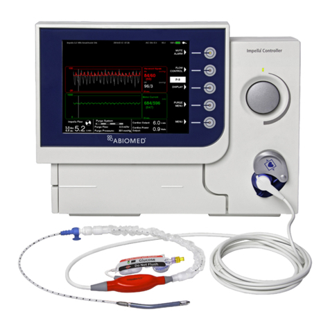
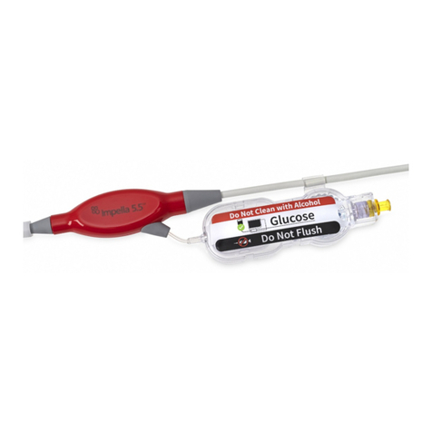
Abiomed Impella RP User manual

Impella®
RP
with the Automated Impella®Controller
Circulatory Support System
INSTRUCTIONS FOR USE
& CLINICAL REFERENCE MANUAL
(United States only)
Humanitarian Device. Authorized by Federal law (USA) to provide circulatory
assistance for up to 14 days in pediatric or adult patients with a body surface
area ≥1.5 m2who develop acute right heart failure or decompensation following
left ventricular assist device implantation, myocardial infarction, heart transplant,
or open-heart surgery. The effectiveness of this device for this use has not been
demonstrated.

IMPORTANT NOTICE: Readthis entire manual beforeusingthe Automated Impella
®
Controller and Impella
®
RPCirculatorySupport
System(Impella
®
RPSystem).TheImpella
®
RPSystem is to be used onlyinaccordance withthismanual.Thismanual is onlyapplicable
toImpella
®
systems using the Automated Impella
®
Controller.
Information containedin this document is subject to change without notice.
©2012 Abiomed
®
, Inc. Allrights reserved.
TheABIOMEDlogoand ABIOMED areregisteredtrademarks of Abiomed, Inc.in theU.S.A. and certain foreign countries.
Recovering hearts.Saving lives. is a trademark of Abiomed, Inc.
Impella is a registered trademark of Abiomed EuropeGmbH, a wholly owned subsidiary of Abiomed, Inc.,in the U.S.A. and certain
foreigncountries.

IMPELLA®RPWITHTHE
AUTOMATEDIMPELLA®CONTROLLER
INSTRUCTIONSFORUSE
&CLINICALREFERENCEMANUAL
(UNITEDSTATESONLY)
Rx Only
Abiomed, Inc.
22 Cherry Hill Drive
Danvers, MA 01923
978-777-5410 (voice)
978-777-8411 (fax)
clinical@abiomed.com (email)
Abiomed EuropeGmbH
Neuenhofer Weg 3
52074Aachen,Germany
+49(241) 8860-0(voice)
+49 (241) 8860-111(fax)
europe@abiomed.com(email)
www.abiomed.com
24-Hour Emergency Hotlines:
N. America 1-800-422-8666
Europe +49 (0)1805 2246633
June2012
Document No. 0046-9051 Rev. A

INTRODUCTION
Introduction .....................................................................................................I
1 INDICATIONS,CONTRAINDICATIONS,ANDPOTENTIAL
ADVERSE
EVENTS
Indications(UnitedStates)...............................................................................1.1
Contraindications(UnitedStates)...................................................................1.1
PotentialAdverseEvents(UnitedStates)........................................................1.2
2 WARNINGSANDCAUTIONS
Warnings........................................................................................................2.1
Cautions......................................................................................................2.3
3 THEIMPELLA®RPCATHETERANDAUTOMATEDIMPELLA®
CONTROLLER
Overview............................................................................................................3.1
Impella®RPCatheter..................................................................................... 3.3
AutomatedImpella®Controller......................................................................3.5
PurgeCassette.................................................................................................3.6
Accessories.......................................................................................................3.8
4 USINGTHEAUTOMATEDIMPELLA
®
CONTROLLER
Overview ..................................................................................................... 4.1
AutomatedImpella
®
ControllerFeatures.........................................................4.1
AutomatedImpella
®
ControllerDisplay............................................................4.5
PlacementScreen............................................................................................4.8
PurgeScreen.................................................................................................4.9
InfusionHistory............................................................................................4.10
MobileOperation...........................................................................................4.11
5 USINGTHEAUTOMATEDIMPELLA
®
CONTROLLER WITHTHE
IMPELLA
®
RP CATHETER
Startup............................................................................................................5.1
CaseStart......................................................................................................5.4
InsertingtheImpella
®
RPCatheter.................................................................5.10
PositioningandStartingtheImpella
®
RPCatheter...........................................5.12
PerformanceLevels.......................................................................................5.13
Suction..........................................................................................................5.13
UseoftheRepositioningSheathandthe23FrPeel-awayIntroducer....... 5.14
PurgeCassetteProcedures............................................................................5.15
TroubleshootingthePurgeSystem...............................................................5.18
PatientWeaning.......................................................................................... 5.20
RemovingtheImpella
®
RPCatheter.............................................................5.20
6 CLINICALEXPERIENCE
PivotalClinicalStudyDesign–RECOVER RIGHT ................................ 6.1
AccountabilityofCohort……..........................................................................6.3
7 AUTOMATEDIMPELLA
®
CONTROLLERALARMS
AlarmsOverview ........................................................................................7.1
AlarmMessageSummary..........................................................................7.3
8 GENERALSYSTEMINFORMATION
Terminology,Abbreviations,andSymbols.....................................................8.1
AutomatedImpella
®
ControllerMechanicalSpecifications..........................8.3
AutomatedImpella
®
ControllerElectricalSpecifications...............................8.3
EquipmentDesign.........................................................................................8.4
EquipmentClassifications ..........................................................................8.4
FederalCommunicationsCommission(FCC)Notice....................................8.5
ElectromagneticCompatibility......................................................................8.5
TransportBetweenHospitals………………………………………...8.10
TransportWithintheHospital………………………………………...8.11
SlaveMonitorConnection..........................................................................8.11
AlarmDelayInformation.............................................................................8.12
PatientEnvironment....................................................................................8.12
WhiteConnectorCable..............................................................................8.13
Impella
®
RPCatheterParameters...............................................................8.13
Cleaning.....................................................................................................8.14
StoringtheAutomatedImpella
®
Controller.................................................8.14
ReturninganImpella
®
RPCathetertoAbiomed(UnitedStates)..................8.14
APPENDICES
AppendixA:AutomatedImpella
®
ControllerMenuStructure................... A.1
..
TABLEOFCONTENTS

FIGURES
Figure3.1 Impella
®
RPCatheterintheHeart..........................................3.1
Figure3.2 AutomatedImpella
®
Controller,Impella
®
RPCatheter,and
Accessories.............................................................................3.2
Figure3.3 Impella
®
RP Catheter.............................................................3.3
Figure3.4 AutomatedImpella
®
Controller–FrontView........................3.5
Figure3.5 PurgeCassette.................................................................... 3.6
Figure3.6 WhiteConnectorCable.........................................................3.8
Figure 3.7 Introducer kit ......................................................................... 3.8
Figure3.8 0.025inch,260cmPlacementGuidewire............................3.8
Figure3.9 DextroseSolution.................................................................3.9
Figure3.10 AutomatedImpella
®
ControllerCart.......................................3.9
Figure4.1 AutomatedImpella
®
ControllerFeatures–FrontView...........4.1
Figure4.2 AutomatedImpella
®
ControllerFeatures–SideViews..........4.3
Figure4.3 AutomatedImpella
®
ControllerDisplayElements.................4.5
Figure4.4 PlacementScreen...................................................................4.8
Figure4.5 PurgeScreen..........................................................................4.9
Figure4.6 InfusionHistoryScreen........................................................4.11
Figure5.1 AutomatedImpella
®
ControllerPowerSwitch.........................5.2
Figure5.2 AutomatedImpella
®
ControllerStartupScreen.......................5.3
Figure5.3 InitialCaseStartScreen.........................................................5.4
Figure5.4 InsertingthePurgeCassetteintotheAutomatedImpella
®
Controller ............................................................................... 5.5
Figure5.5 InsertingtheCatheterPlugintotheConnectorCable.........5.6
Figure5.6 SnappingPlasticCliptoConnectorCable............................5.6
Figure5.7 PrimingtheImpellaPurgeLumen..........................................5.7
Figure5.8 ConnectingtheLuertotheImpella
®
RPCatheter..................5.7
Figure5.9 EnteringPurgeFluidInformation..........................................5.8
Figure5.10 ConnectingthePurgeTubingtotheConnectorCable...........5.9
Figure5.11 Impella
®
RPSystemConfiguration.........................................5.9
Figure5.12 MaximumPerformanceLevel..................................................5.12
Figure5.13 DisconnectingtheYConnectorfromthePurgeCassette
Tubing......................................................................................5.15
Figure6.1 StudyFlow Schematic …………………………………. 6.3
Figure6.2 Cardiacindexandcentralvenouspressuremeasured
duringthestudy………………………………………….6.8
Figure6.3 LVADflowchangesfrom baselinetoon-support……….6.8
Figure6.4 Useofinotropes duringImpellaRPsupport..…………. 6.9
Figure6.5 Right ventricularfunctionchanges………………………6.10
Figure7.1 AlarmWindow......................................................................7.2
Figure 8.1 AutomatedImpella
®
ControllerPatientEnvironment............8.12
TABLES
Table3.1 Impella
®
RP CatheterComponents ..........................................3.3
Table3.2 PurgeCassetteComponents .................................................... 3.7
Table3.3 Impella
®
RPCatheterandAutomatedImpella
®
Controller
Accessories.................................................................................3.8
Table4.1 AutomatedImpella
®
ControllerFrontViewFeatures..................4.2
Table4.2 AutomatedImpella
®
ControllerSideViewFeatures...................4.4
Table4.3 AutomatedImpella
®
ControllerDisplayElements.....................4.5
Table5.1 PerformanceLevelFlowRates.................................................5.13
Table6.1 Patient Characteristics...............................................................6.4
Table6.2 BaselineLaboratoryParameters………………………….. 6.5
Table6.3 ProceduralCharacteristics …………………………………6.6
Table6.4 SupportandHemodynamicCharacteristics ………………. 6.6
Table6.5 Patient Outcome …………………………………………… 6.7
Table6.6 SecondarySafetyEndpoints ………………………………. 6.7
Table7.1 AlarmLevels..............................................................................7.1
Table7.2 AutomatedImpella
®
ControllerAlarmMessages .....................7.3
TABLEOFCONTENTS

INTRODUCTION
PURPOSE OF MANUAL
This Instructions for Use & Clinical Reference Manual is designed for healthcare professionals. It
contains clinical and technical information to guide healthcare professionals in their use of the
Impella® RP Catheter with the Automated Impella® Controller. The Impella® RP System performs
life-sustaining functions. To use the system you must understand and follow these instructions. The
Impella® RP System may be used only for its intended purpose.
MANUAL OVERVIEW
This manual provides instructions for use of the Impella
®
RP Catheter with the Automated Impella®
Controller. The following summarizes the contents of each section of the manual.
•
Section 1: Indications, Contraindications, and Potential Adverse Events
discusses
indications for use of the Impella
®
RP Catheter with the Automated Impella
®
Controller,
contraindications, and potential adverse events that may be associated with the use of the
system.
•
Section 2: Warnings and Cautions
discusses the warnings and cautions pertaining to the
use of the Impella
®
RP Catheter with the Automated Impella
®
Controller.
•
Section 3: The Impella® RP Catheter and Automated Impella® Controller
provides an
overview of the system and describes its major components and features.
•
Section 4: Using the Automated Impella® Controller
describes the controls and various
screen types on the Automated Impella® Controller.
•
Section 5: Using the Automated Impella® Controller with the Impella® RP Catheter
provides the procedures for using the Impella® RP System.
•
Section 6: Clinical Experience
provides an overview of the RECOVER RIGHT trial, which
studied the use of the Impella® RP System in a U.S. clinical trial. The results of this trial
were reviewed by the FDA prior to its approval of the Impella® RP System.
•
Section 7: Automated Impella® Controller Alarms
provides a listing of Automated
Impella® Controller alarms as well as information on what to do to resolve them.
•
Section 8: General System Information
contains information including definitions for key
terms that appear in the manual, descriptions of the abbreviations and symbols that appear
on Impella® RP Catheter and Automated Impella® Controller components and packaging,
technical information pertaining to the Impella® RP Catheter and Automated Impella®
Controller, and instructions on cleaning and storing system components as well as returning
components to Abiomed.
•
Appendices
at the end of the manual provide supplemental information about topics
including the Automated Impella® Controller menu structure.
Impella
®
RP with the Automated Impella
®
Controller
I

1
INDICATIONS, CONTRAINDICATIONS,
AND POTENTIAL ADVERSE EVENTS
INDICATIONS (UNITED STATES) ...................................................................... 1.1
CONTRAINDICATIONS (UNITED STATES)…................................................... 1.1
POTENTIAL ADVERSE EVENTS (UNITED STATES) ......................................... 1.2

INDICATIONS (UNITED STATES)
The Impella RP System is indicated for providing circulatory assistance for up to 14 days in pediatric
or adult patients with a body surface area ≥1.5 m
2
who develop acute right heart failure or
decompensation following left ventricular assist device implantation, myocardial infarction, heart
transplant, or open-heart surgery.
CONTRAINDICATIONS (UNITED STATES)
• Disorders of the pulmonary artery wall that would preclude placement or correct positioning
of the Impella RP device
• Mechanical valves, severe valvular stenosis or valvular regurgitation of the tricuspid valve
or pulmonary valve
• Mural thrombus of the right atrium or vena cava
• Anatomic conditions precluding insertion of the pump
• Other illnesses or therapy requirements precluding use of the pump
• Presence of a vena cava filter or caval interruption device, unless there is clear access from
the femoral vein to the right atrium that is large enough to accommodate a 22 Fr catheter
Impella®RP with the Automated Impella®Controller
1.1

1.2 Instructions for Use & Clinical Reference Manual (US)
POTENTIAL ADVERSE EVENTS (UNITED STATES)
Below is a list of the potential adverse effects (e.g., complications) associated with the use of the
Impella RP system:
• Arrhythmia
• Atrial fibrillation
• Bleeding
• Cardiac tamponade
• Cardiogenic shock
• Death
• Device Malfunction
• Hemolysis
• Hepatic failure
• Insertion site infection
• Perforation
•
Phlegmasia cerulea dolens (a severe form of deep venous thrombosis)
• Pulmonary valve insufficiency
• Respiratory dysfunction
• Sepsis
• Thrombocytopenia
• Thrombotic vascular (non-central nervous system) complication
• Tricuspid valve injury
• Vascular injury
•
Venous thrombosis
•
Ventricular fibrillation and/or tachycardia

2
WARNINGS AND CAUTIONS
WARNINGS...................................................................................................
2
.1
CAUTIONS...................................................................................................
2
.3

WARNINGS
The Impella
®
RP System is intended for use only by personnel trained in accordance
with the Abiomed Training Program.
Fluoroscopy is required to guide placement of the Impella
®
RP Catheter. The small
placement guidewire must be reliably observed at all times.
Be sure that the stopcock on the repositioning sheath is always keptin the closed
position. Significant bleed back can result if the stopcock is open.
Avoid manual compression of the inlet,outlet, or sensor areas of the cannula
assembly.
The sterile components of the Impella
®
RPSystem can be used only if the
sterilization indicators show that the contents have been sterilized, the packaging is
not damaged, and the expiration date has not elapsed.
Do
NOT
resterilize or reuse the Impella
®
RP Catheter. Itis a disposable device
and is intended for single use only. Reuse, reprocessing, reinserting through the
introducer, or resterilization may compromise the structural integrity of the catheter
and/or lead to catheter failure which, in turn, may result in patient injury, illness, or
death.
Retrograde flow will occur from the pulmonary artery back into the inferior vena
cava if the Impella
®
RP Catheter is set at performance level P0.
Do
NOT
use saline in the purge system.
Do
NOT
use an Impella® RP System if any part of the system is damaged.
To prevent the risk of explosion, do NOT operate the Impella® RP System near
flammable anesthetics.
If at any time during the course of support with the Impella® RP Catheter, the
Automated Impella® Controller alarms “Purge Pressure Low” or “Purge System
Open,” follow the instructions presented in section 5 of this manual.
Do
NOT
subject a patient who has been implanted with an Impella
®
RP Catheter to
magnetic resonance imaging (MRI). The strong magnetic energy produced by an MRI
machine may cause the Impella
®
RP System components to stop working, and result
in injuries to the patient. An MRI may also damage
the electronics of the Impella® RP
System.
Cardiopulmonary support (CPR) should be initiated immediately per hospital
protocol if indicated for any patient supported with the Impella® RP Catheter. When
initiating CPR, reduce the Impella® RPCatheter flow rate. When cardiac function
hasbeen restored, return flow rate to the previous level and assess the placement
signal on the controller.
During defibrillation, do
NOT
touch the Impella® RPCatheter, cables, or
Automated Impella® Controller.
Impella
®
RP with the Automated Impella
®
Controller
Warnings
Warnings alert you to
situationsthatcancause
deathor serious injury. The
red symbol appears
before warningmessages.
2.1

2.2
Power the Automated Impella® Controller using its internal battery if the integrity
of the protective earth conductor is questionable.
Medical electrical equipment needs special precautions regarding EMC and needs
to
be installed and put into service according to the electromagnetic compatibility (EMC)
information provided in section 7 of this manual.
During transport, the Automated Impella® Controller may be exposed to stronger
electromagnetic disturbance than during in-hospital use. Strong electromagnetic
disturbance may cause the Automated Impella® Controller to display soft button
menu selections that were not selected by the user. Operators should be aware that,
under these conditions, the operating parameters are not affected. No user intervention
is required. Monitor Impella® RP Catheter flow and patient hemodynamics to confirm
normal operation. The condition will resolve itself once the Automated Impella®Controller
is no longer exposed to the disturbance.
Portable and mobile RF communications equipment can affectmedical electrical
equipment.
The equipment or system should not be used adjacent to or stacked with other
equipment. If adjacent or stacked use is necessary, the equipment or system should
be observed to verify normal operation in the configuration in which it will be used.
Use of cables, other than those sold by Abiomed, may result in increased emissions
or decreased immunity of the Automated Impella® Controller.
The Automated Impella® Controlleruses RFID (radio frequency identification) to
identify and communicate with the purge cassette. Other equipment may interfere with
the Automated Impella® Controller even if that other equipment complies with CISPR
emission requirements.
Avoid overinserting the Impella®RP Catheter and possibly impinging the catheter
tip against the walls of the vasculature, atrium, or ventricle.
Torquing the catheter should be monitored carefully using fluoroscopy.
Do
NOT
advance or withdraw the Impella® RP Catheter against resistance without
using fluoroscopy to determine the cause of the resistance. Doing so could result
in separation of the catheter or guidewire tip, damage to the catheter or vessel, or
perforation.
Instructions for Use & Clinical ReferenceManual (US)

CAUTIONS
Handle with care. The Impella® RP Catheter can be damaged during removal from
packaging, preparation, insertion, and removal. Do
NOT
bend, pull, or place excess
pressure on the catheter or mechanical components at any time.
Patients with tricuspid or pulmonary valve stenosis or insufficiency, and patients
with prosthetic tricuspid or pulmonary valves, may be compromised by the use of
the Impella® RP Catheter.
Use only original accessories and replacement parts supplied by Abiomed.
Do
NOT
use damaged or contaminated connector cables.
To prevent device failure, do
NOT
start the Impella® RP Catheter until the
placement guidewire has been removed.
Do
NOT
remove the Impella® RP Catheter over the length of the placement
guidewire.
When replacing the purge cassette, the replacement process must be completed
within 2 minutes. The Impella® RP Catheter may be damaged if replacement takes
longer than 2 minutes.
To prevent malfunction of the Automated Impella® Controller, avoid long-term
exposure to direct sunlight and excessive heat (40°C).
To prevent overheating and improper operation, do
NOT
block the cooling vents of
the Automated Impella® Controller while it is operating.
Do
NOT
kink or clamp any part of the Impella® RP Catheter.
Do
NOT
use the Impella® RP Catheter with a damaged or kinked introducer.
Replace the introducer if a kink is observed.
The Li-Ion batteries must be charged for 5 hours prior to system operation in order
to meet the runtime requirement of 1 hour. Failure to do so will yield a shorter
runtime. After being unplugged, the Automated Impella® Controller will operate for
at least 60 minutes after the batteries have been fully charged.
Minimize exposure of Impella® RP System components to sources of electromagnetic
interference (EMI). Exposure to sources of EMI, such as cell phones and two-way
radios, may cause operational interference. To clear interference, either increase the
distancebetween system components and the EMI source or turn off the EMI source.
Operation of Impella® RP System components may interfere with the operation of
other devices. If interference occurs, increase the distance between the deviceand
system components.
Impella
®
RP with the Automated Impella
®
Controller
Cautions
Cautions indicatesituations
in which equipment may
malfunction, be damaged, or
ceaseto operate. Theyellow
symbol appears before
caution messages.
2.3

2.4
Have a backup Automated Impella® Controller, purge cassette, connector cable,
and Impella® RPCatheter available in the unlikely event of a device failure.
Do
NOT
use the bed mount as a handle.
Insertion through the left femoral vein may result in repeated attempts to properly
position the Impella RP, which could cause excessive manipulation and pump
damage. As a result, left femoral insertion should be avoided whenever possible.
Instructions for Use & Clinical ReferenceManual (US)

3 THE IMPELLA® RP CATHETER
AND AUTOMATED IMPELLA® CONTROLLER
OVERVIEW.................................................................................................... 3.1
ReusableSystemComponents............................................................................3.2
Single-useSystemComponents..........................................................................3.2
System Configuration.........................................................................................3.2
IMPELLA
®
RPCATHETER................................................................................ 3.3
DifferentialPressureSensor...............................................................................3.4
AUTOMATEDIMPELLA
®
CONTROLLER............................................................3.5
PURGECASSETTE ........................................................................................... 3.6
ACCESSORIES............................................................................................... 3.8

OVERVIEW
The Impella
®
RP Catheter is an intracardiac microaxial blood pump that supports a patient’s
pulmonary circulation. The Impella
®
RP Catheter is inserted percutaneously through the femoral
vein and into the pulmonary artery (see Figure 3.1).
Outlet area
inPA
Inlet area
inIVC
FemoralVein
Insertion
Figure 3.1 Impella
®
RP Catheter in the Heart
When properly positioned, the Impella® RP Catheter delivers blood from the inlet area, which sits in
the inferior vena cava, through the cannula, to the outlet opening in the pulmonary artery.
Physicians and device operators monitor Impella® RP Catheter function on the display screen of
the Automated Impella® Controller.
The intent of the therapy with the Impella RP System is to provide a percutaneous circulatory
support system to restore normal right heart hemodynamics, reduce right ventricular work, and
allow the right heart time to potentially recover adequate contractile function or to be bridged to the
next therapy.
This section describes the components of the Impella
®
RP Catheter and the Automated Impella
®
Controller, as well as the accessory components.
Impella
®
RP with the Automated Impella
®
Controller
3.1

3.2
REUSABLE SYSTEMCOMPONENTS
The Impella
®
RP System consists of the following reusable components:
• Automated Impella® Controller—provides the user interface, alarm indications, and
portable battery
• Automated Impella® Controller cart—for easy transport of the Automated Impella®
Controller
SINGLE-USE SYSTEMCOMPONENTS
The Impella® RP System also includes the following single-use components:
• Impella® RP Catheter
• Purge cassette
• Introducer kit
• Connector cable
SYSTEM CONFIGURATION
Figure 3.2 illustrates how the Automated Impella® Controller connects to the Impella® RP
Catheter and accessory components.
Disconnect Y Connector from Purge Tubing
Dextrose
Solution
Automated Impella
®
Controller
Impella
®
RP Catheter
Connector
Cable
PurgeCassette
Figure 3.2 Automated Impella
®
Controller, Impella
®
RP Catheter, and Accessories
Instructions for Use & Clinical ReferenceManual (US)
ConnectPurgeTubing
Directlyto Impella
®
RPCatheter

Repositioning Unit
Component
Pigtail
Outlet area
Cannula
Differential pressure
sensor
Blue Impella
®
Plug
Pigtail
Clear
Sidearm
Check
Valve
Catheter
Shaft
Inlet Area
Motor Housing
Description
The 6 Fr pigtail is attached to the cannula at the distal end of the
outlet area. It assists with stabilizing the catheter in the correct
position in the pulmonary artery.
The outlet area, located at the distal tip of the cannula, has 5 openings
(windows) that allow blood to exit the cannula.
The 22 Fr cannula is designed for the anatomy of the right heart, to
provide optimal and stable position during operation. The cannula
is made of nitinol and covered in polyurethane with spiral shaped
reinforcement integrated into the cannula.
A sensor that measures the pressure difference between the inside and
outside of the cannula. The pressure value is used for monitoring low
during catheter operation.
3.3
IMPELLA
®
RP CATHETER
The Impella® RP Catheter is an intracardiac microaxial blood pump that delivers up to 4.0 liters of blood
per minute from the inferior vena cava into the pulmonary artery. Figure 3.3 illustrates the Impella® RP
Catheter. The Impella® RP Catheter has a specially designed three dimensional cannula that is sized to
fit through the vessels and hearts of pediatric and adult patients with a Body Surface Area (BSA) equal
to or greater than 1.5 m
2
. Table 3.1 describes each component from the pigtail at one end to the check
valve on the other end.
Figure 3.3 Impella
®
RP Catheter
Table 3.1 Impella
®
RP Catheter Components
Impella
®
RP with the Automated Impella
®
Controller
Infusion
Filter Pressure
Reservoir
Differential
Pressure
Sensor
Cannula
Outlet
Area

3.4
Component
Inlet area
Motor housing
Catheter shaft
Repositioning unit
Blue Impella® plug
Clear sidearm
Infusion filter
Pressure reservoir
Check valve
Description
The proximal end of the cannula is attached to the inlet area where
blood enters the cannula.
The 21 Fr motor housing consists of an encapsulated motor.
An 11 Fr catheter shaft is located between the motor housing and
the blue Impella® plug. The lumen of the catheter shaftcontains
a purge lumen, an electrical cable, and a differential pressure
measurement cable.
The catheter shaft has transversal marks:
• The transversal marks at 1 cm intervals aid in proper positioning.
The repositioning unit consists of a sheath and an anticontamination
sleeve with an anchoring ring.
• The 11 Fr sheath (14 Fr outer diameter) with hemostatic valve
is located on the catheter shaft and allows repositioning of the
catheter.
• The anchoring ring of the anticontamination sleeve secures the
sheath to the catheter; turning in the counterclockwise direction
enables movement of the catheter and turning in the clockwise
direction disables movement.
The blue Impella® plug has a clear sidearm and contains memory
that retains operating parameters in case the patientneeds to be
transferred to another controller.The plug connects the Impella® RP
Catheter to the Automated Impella® Controller through a connector
cable.
The clear sidearm is attached to the purge cassette tubing. It leads to
the infusion filter, the pressure reservoir, and the check valve.
The infusion filter prevents bacterial contamination and prevents air
from entering the purge lumen.
The pressure reservoir includes a flexible rubber diaphragm that
provides additional filling volume by means of an expansion chamber
during purge solution change.
The yellow check valve ensures that purge fluid does not flow in the
reverse direction when the purge solution is exchanged.
Instructions for Use & Clinical ReferenceManual (US)
Table 3.1 Impella
®
RP Catheter Components (continued)
DIFFERENTIAL
PRESSURESENSOR
The Impella® RP Catheter has an electronic differential pressure sensor located at the proximal
end of the cannula. The purpose of the pressure sensor is to generate the placement signal used
to calculate the low generated by the Impella® RP Catheter.
The pressure sensor is a flexible membrane integrated into the cannula. One side of the sensor
is exposed to the blood pressure on the outside of the inlet area and the other side is exposed
to the pressure of the blood inside of the cannula. The sensor generates an electrical signal
proportional to the difference between the pressure outside the inlet area and the pressure
inside the cannula. This signal is displayed on the Automated Impella® Controller as the
placement signal.

AUTOMATED IMPELLA
®
CONTROLLER
The Automated Impella® Controller (see Figure 3.4) provides three vital functions to the operation of
the Impella® RP Catheter:
• The controller provides an interface for monitoring and controlling the function of the Impella
®
RP Catheter
• The controller provides a fluid purge to the Impella
®
RP Catheter
• The controller provides backup power when the Impella
®
RP System is operated away
from AC power
The controller weighs 26 lbs (11.8 kg) and can operate on its internal battery for at least 60 minutes
when fully charged. Using the controller, the Impella RP System can be used by trained healthcare
professionals in healthcare facilities and during medical transport (i.e., ambulance, helicopter, or
fixed-winged aircraft) environments.
The Automated Impella® Controller operation is described in detail in section 4 of this manual.
Figure 3.4 Automated Impella
®
Controller – Front View
Impella
®
RP with the Automated Impella
®
Controller
Automated Impella
®
Controller Battery Power
The controller canoperate
on its internal lithium-ion
(Li-Ion) battery for at least 60
minuteswhenfully charged.
3.5
Table of contents
Other Abiomed Medical Equipment manuals
Popular Medical Equipment manuals by other brands

UV MEDICO
UV MEDICO UV222 Technical and installation manual

Keeler
Keeler TonoCare 2.0 Three step guide

Dynatech
Dynatech DS6100 Operating and service manual

Precision Medical
Precision Medical Easy Go Vac PM66 Series user manual

Cardioline
Cardioline AR 600 user manual

Otto Bock
Otto Bock Invader 480S26 10000 K Instructions for use