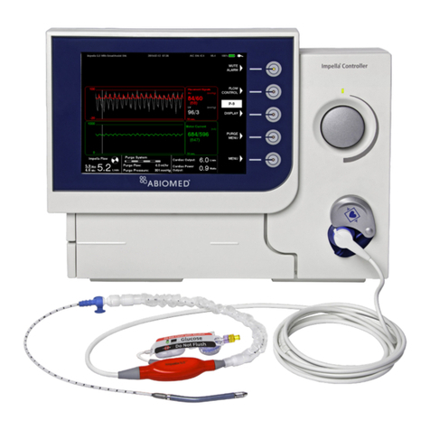
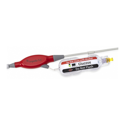
Abiomed Impella 2.5 User manual

Impella®2.5, 5.0, LD and Impella CP®
INSTRUCTIONS FOR USE
& CLINICAL REFERENCE MANUAL
(United States only)
Impella Ventricular
Support Systems
for Use During Cardiogenic Shock

IMPORTANT NOTICE: Read this entire manual before using the Automated Impella®Controller and Impella®2.5, 5.0, LD, or Impella CP®Circulatory
Support System (Impella®System). The Impella®System is to be used only in accordance with this manual. This manual is only applicable to Impella®
Systems using the Automated Impella®Controller.
Information contained in this document is subject to change without notice.
©2015 Abiomed®, Inc. All rights reserved.
The ABIOMED logo and ABIOMED are registered trademarks of Abiomed, Inc. in the U.S.A. and certain foreign countries.
Recovering hearts. Saving lives.
is a trademark of Abiomed, Inc.
Impella is a registered trademark of Abiomed Europe GmbH, a wholly owned subsidiary of Abiomed, Inc., in the U.S.A. and certain foreign countries.

Abiomed, Inc.
22 Cherry Hill Drive
Danvers, MA 01923
978-777-5410 (voice)
978-777-8411 (fax)
[email protected] (email)
Abiomed Europe GmbH
Neuenhofer Weg 3
52074 Aachen, Germany
+49 (241) 8860-0 (voice)
+49 (241) 8860-111 (fax)
[email protected] (email)
www.abiomed.com
24-Hour Clinical Support Center:
N. America 1-800-422-8666
Europe +49 (0) 1805 2246633
March 2016
Document No. xxxx-xxxx Rev. A
Rx Only
IMPELLA VENTRICULAR SUPPORT SYSTEMS
FOR USE DURING CARDIOGENIC SHOCK
INSTRUCTIONS FOR USE
& CLINICAL REFERENCE MANUAL
(UNITED STATES ONLY)


TABLE OF CONTENTS
INTRODUCTION
Introduction............................................................................................. I
1 INDICATIONS, CONTRAINDICATIONS, AND POTENTIAL ADVERSE
EVENTS
Indications (United States) ....................................................................... 1.1
Contraindications (United States)............................................................. 1.1
Potential Adverse Events (United States).................................................. 1.2
2 WARNINGS AND CAUTIONS
Warnings ................................................................................................. 2.1
Cautions .................................................................................................. 2.3
3 THE IMPELLA®CATHETER AND AUTOMATED IMPELLA®
CONTROLLER
Overview ................................................................................................. 3.1
Impella®Catheter .................................................................................... 3.5
Automated Impella®Controller................................................................ 3.11
Purge Cassette......................................................................................... 3.12
Accessories.............................................................................................. 3.14
4 USING THE AUTOMATED IMPELLA®CONTROLLER
Overview ................................................................................................. 4.1
Automated Impella®Controller Features.................................................. 4.2
Home Screen............................................................................................ 4.6
Placement Screen..................................................................................... 4.9
Purge Screen............................................................................................ 4.10
Infusion History Screen ............................................................................ 4.11
Mobile Operation..................................................................................... 4.12
5 USING THE AUTOMATED IMPELLA®CONTROLLER
WITH THE IMPELLA®CATHETER
Pre-support Evaluation ............................................................................ 5.1
Startup..................................................................................................... 5.2
Case Start ................................................................................................ 5.5
Impella®2.5 Catheter Insertion (Wired) ................................................... 5.12
Wireless Insertion of the Impella®2.5 Catheter........................................ 5.16
Impella CP®Catheter Insertion ................................................................ 5.17
Axillary Insertion of the Impella®2.5, 5.0, or Impella CP®Catheter ......... 5.21
Alternate Insertion Technique for the Impella®5.0 Catheter..................... 5.25
Implanting and Starting the Impella®LD Catheter.................................... 5.29
Positioning and Starting the Impella®2.5 and Impella CP®Catheters ...... 5.32
Positioning and Starting the Impella®5.0 Catheter .................................. 5.38
Positioning and Starting the Impella®LD Catheter ................................... 5.41
Purge Cassette Procedures....................................................................... 5.44
Troubleshooting the Purge System ........................................................... 5.48
Patient Weaning ...................................................................................... 5.49
Removing the Impella®2.5, 5.0, or Impella CP®Catheter ........................ 5.50
Explanting the Impella®LD Catheter........................................................ 5.52
6 CLINICAL EXPERIENCE
Cardiac Shock After Myocardial Infarction ............................................... 6.1
Summary of Primary Clinical Studies ........................................................ 6.1
Summary of Supplemental Clinical Information ....................................... 6.7
Cardiac Shock After Open Heart Surgery ................................................. 6.17
Summary of Primary Clinical Studies ........................................................ 6.17
Summary of Supplemental Clinical Information ....................................... 6.23
7 PATIENT MANAGEMENT TOPICS
Patient Management Overview ................................................................ 7.1
General Patient Care Considerations ....................................................... 7.1
Transport Within the Hospital .................................................................. 7.2
Right Heart Failure................................................................................... 7.2
ECG Interference...................................................................................... 7.3
Latex........................................................................................................ 7.3
Use of Echocardiography for Positioning of the Impella®Catheter............ 7.3
Understanding and Managing Impella®Catheter Position Alarms............. 7.10
Impella Stopped....................................................................................... 7.18
Suction .................................................................................................... 7.18
Hemolysis ................................................................................................ 7.19
Operating the Impella®Catheter without Heparin in the Purge Solution .. 7.21
Placement Signal Lumen (for Impella®2.5 and Impella CP®) .................... 7.21
Pressure Sensor Drift and Sensor Failure (for Impella®5.0 and LD)........... 7.23
Enabling Purge Flow Notifications............................................................ 7.24
Disabling Audio for Placement Signal Lumen Blocked Alarm
(Impella®2.5 and Impella CP®) ................................................................ 7.24
Surgical Mode.......................................................................................... 7.25
Timed Data Recording.............................................................................. 7.25
Operating the Impella®Catheter in Electromagnetic Fields ...................... 7.26
Transferring from the Automated Impella®Controller to a New
Automated Impella®Controller................................................................ 7.28
Emergency Shutdown Procedure.............................................................. 7.29
8 AUTOMATED IMPELLA®CONTROLLER ALARMS
Alarms Overview...................................................................................... 8.1
Alarm Message Summary......................................................................... 8.3
9 GENERAL SYSTEM INFORMATION
Terminology, Abbreviations, and Symbols ................................................ 9.1
Automated Impella®Controller Mechanical Specifications ....................... 9.3
Automated Impella®Controller Electrical Specifications........................... 9.3
Equipment Design.................................................................................... 9.4
Equipment Classifications ........................................................................ 9.5
Federal Communications Commission (FCC) Notice.................................. 9.5
Electromagnetic Compatibility ................................................................. 9.6
Transport Between Hospitals ................................................................... 9.7
Slave Monitor Connection........................................................................ 9.11
Alarm Delay Information .......................................................................... 9.12
Patient Environment................................................................................. 9.12
White Connector Cable............................................................................ 9.13
Impella®Catheter Parameters.................................................................. 9.13
Impella®2.5 Catheter Dimensions............................................................ 9.14
Impella CP®Catheter Dimensions ............................................................ 9.14
Impella®5.0 Catheter Dimensions............................................................ 9.15
Impella®LD Catheter Dimensions............................................................. 9.15
Cleaning .................................................................................................. 9.16
Storing the Automated Impella®Controller .............................................. 9.16
Returning an Impella®Catheter to Abiomed (United States)..................... 9.16
APPENDICES
Appendix A: Impella®System Limited Service Warranty (United States) .. A.1
Appendix B: Abiomed-Approved Guidewires and Introducers
(Impella®2.5 and Impella CP®) ................................................................ B.1
Appendix C: Automated Impella®Controller Menu Structure .................. C.1

TABLE OF CONTENTS
FIGURES
Figure 3.1 Impella®Catheter in the Heart................................................. 3.1
Figure 3.2a Set-up Configuration of the Automated Impella®Controller,
Impella® 2.5 or Impella CP®Catheter, and Accessories
(Impella CP®shown)................................................................ 3.3
Figure 3.2b Standard Configuration of the Automated Impella®Controller,
Impella®2.5 or Impella CP®Catheter, and Accessories
(Impella CP®shown)................................................................ 3.3
Figure 3.3 Set-up Configuration of the Automated Impella®Controller,
Impella®5.0 or LD Catheter, and Accessories
(Impella®5.0 shown) ............................................................... 3.4
Figure 3.4 Impella®Catheters................................................................... 3.5
Figure 3.5 Impella®5.0 and LD Differential Pressure Sensor
(Impella®5.0 shown) ............................................................... 3.9
Figure 3.6 Electrical Signal Generated by the Cardiac Cycle ...................... 3.9
Figure 3.7 Correct Impella®5.0/LD Catheter Positioning and Pulsatile
Placement Signal ..................................................................... 3.10
Figure 3.8 Incorrect Impella®5.0/LD Catheter Positioning and Flat
Placement Signal ..................................................................... 3.10
Figure 3.9 Automated Impella®Controller – Front View ........................... 3.11
Figure 3.10 Purge Cassette ........................................................................ 3.12
Figure 3.11 White Connector Cable............................................................ 3.14
Figure 3.12 Impella®2.5 Introducer Kit ...................................................... 3.14
Figure 3.13 Impella CP®Introducer Kit ....................................................... 3.14
Figure 3.14 Silicone Plugs (Impella®5.0/LD) ............................................... 3.14
Figure 3.15 Impella®Axillary Insertion Kit
(Impella®2.5, 5.0, and Impella CP®)........................................ 3.15
Figure 3.16 Placement Guidewire............................................................... 3.15
Figure 3.17 Dextrose Solution .................................................................... 3.15
Figure 3.18 Automated Impella®Controller Cart ........................................ 3.15
Figure 4.1 Automated Impella®Controller Features – Front View............. 4.2
Figure 4.2 Automated Impella®Controller Features – Side Views............. 4.4
Figure 4.3 Home Screen ........................................................................... 4.6
Figure 4.4 Placement Screen..................................................................... 4.9
Figure 4.5 Purge Screen............................................................................ 4.10
Figure 4.6 Infusion History Screen ............................................................ 4.12
Figure 5.1 Automated Impella®Controller Power Switch .......................... 5.3
Figure 5.2 Automated Impella®Controller Startup Screen ........................ 5.4
Figure 5.3 Initial Case Start Screen........................................................... 5.5
Figure 5.4 Inserting Purge Cassette into Automated Impella®Controller .. 5.6
Figure 5.5 Inserting the Catheter Plug into the Connector Cable .............. 5.7
Figure 5.6 Snapping Plastic Clip to Connector Cable
(Impella CP®shown) .................................................................5.7
Figure 5.7 Priming the Impella Purge Lumen............................................. 5.8
Figure 5.8 Connecting the Luer(s) to the Impella®Catheter
(Impella CP®shown)................................................................ 5.8
Figure 5.9 Priming the Placement Signal Lumen ....................................... 5.9
Figure 5.10 Squeezing the White Flush Valve to Prime the Placement
Signal Lumen........................................................................... 5.9
Figure 5.11 Entering Purge Fluid Information.............................................. 5.10
Figure 5.12 Connecting the Purge Tubing to the Connector Cable.............. 5.11
Figure 5.13 Set-up Configuration of the Impella®System
(Impella CP®shown)................................................................ 5.11
Figure 5.14 Inserting the Peel-Away Introducer.......................................... 5.12
Figure 5.15 Inserting the Diagnostic Catheter............................................. 5.13
Figure 5.16 Loading the Catheter on the Guidewire using the
EasyGuide Lumen .................................................................... 5.13
Figure 5.17 Loading the Catheter on the Guidewire without the
EasyGuide Lumen and Aligning the Placement Guidewire........ 5.14
Figure 5.18 Inserting the Impella®Catheter................................................ 5.15
Figure 5.19 Aortic Waveform on Placement Signal Screen .......................... 5.15
Figure 5.20 Inserting the Peel-Away Introducer.......................................... 5.17
Figure 5.21 Inserting the Diagnostic Catheter............................................. 5.18
Figure 5.22 Loading the Catheter on the Guidewire using the
EasyGuide Lumen .................................................................... 5.18
Figure 5.23 Loading the Catheter on the Guidewire without the
EasyGuide Lumen and Aligning the Placement Guidewire........ 5.19
Figure 5.24 Inserting the Impella®Catheter................................................ 5.20
Figure 5.25 Aortic Waveform on Placement Screen..................................... 5.20
Figure 5.26 Introducer, Graft Lock, and Hemashield Platinum Graft
(Graft Not Supplied)................................................................. 5.22
Figure 5.27 Correct Positioning If Second Graft Lock Required ................... 5.22
Figure 5.28 Closing the Graft Lock ............................................................. 5.23
Figure 5.29 Releasing the Graft Lock.......................................................... 5.24
Figure 5.30 Cut-Down Insertion of the Impella®5.0 Catheter..................... 5.25
Figure 5.31 Guidewire Placement............................................................... 5.26
Figure 5.32 Femoral Artery Insertion of the Impella®5.0 Catheter Using
a Sidearm Graft ....................................................................... 5.27
Figure 5.33 Impella®LD Catheter with Silicone Plugs ................................. 5.30
Figure 5.34 Waveform as Catheter is Advanced into the Aorta................... 5.30
Figure 5.35 Pulsatile Waveform on Placement Signal Screen....................... 5.31
Figure 5.36 Starting the Impella®2.5 and Impella CP®Catheter................. 5.32
Figure 5.37 FLOW CONTROL Options for the Impella®2.5 and
Impella CP® Catheter ............................................................... 5.32
Figure 5.38 Ventricular Waveform on Placement Signal Screen................... 5.33
Figure 5.39 Transfer to P-level Mode.......................................................... 5.33
Figure 5.40 Adjusting P-level...................................................................... 5.35
Figure 5.41 Removing the Peel-Away Introducer (14 Fr Introducer shown).. 5.35
Figure 5.42 Standard Configuration for Impella®System after Transfer
from the Set-up Configuration ................................................. 5.37
Figure 5.43 Waveform as Catheter is Advanced into the Aorta ................... 5.38
Figure 5.44 Pulsatile Waveform on Placement Screen................................. 5.39
Figure 5.45 Selecting P-level ...................................................................... 5.39
Figure 5.46 Confirming Placement on the Placement Signal Screen ............ 5.40
Figure 5.47 Selecting P-Level...................................................................... 5.41
Figure 5.48 Confirming Placement on the Placement Signal Screen ............ 5.42
Figure 5.49 Impella®LD Catheter After Implantation.................................. 5.43
Figure 5.50 Disconnecting the Y Connector from the Purge Cassette
Tubing ..................................................................................... 5.45
Figure 5.51 Removing the Stylet................................................................. 5.50
Figure 5.52 Inserting the Guidewire with the Cheater................................. 5.51
Figure 5.53 Loosening the Tuohy-Borst Valve............................................. 5.51
Figure 6.1 Kaplan-Meier Survival Curves Survival (to 30 days) for the ISAR-
SHOCK Trial ............................................................................. 6.4
Figure 6.2 Lactate Levels Seen Post-Implant During the Trial .................... 6.5
Figure 6.3 Increase in Cardiac Index from Baseline, Impella vs. IABP 30
Minutes Post-Support, in Patients Treated for Cardiogenic Shock
After an AMI (ISAR-SHOCK)..................................................... 6.5
Figure 6.4 Change in Inotropic Dosage at 24 Hours, Impella vs. IABP
in Patients Treated for Cardiogenic Shock After an AMI
(ISAR-SHOCK) ......................................................................... 6.6
Figure 6.5 Time Intervals for Impella Implants Data Collection by Type of
Device ..................................................................................... 6.8
Figure 6.6 Kaplan-Meier Curve Estimates for 30 Day Survival - All Patient
Cohort .................................................................................... 6.9
Figure 6.7 Kaplan-Meier Curve Estimates for 30 Day Survival (by Device) - All
Patient Cohort ........................................................................ 6.9
Figure 6.8 Outcomes Between Impella Registry Subgroups: Patients Likely to
be Eligible for RCTs vs. Patients Likely to be Excluded from RCTs
(“Salvage” Patients) ................................................................ 6.10
Figure 6.9 30-Day Outcomes (by Device) Between Impella Registry Subgroups:
Patients Likely to be Eligible for RCTs vs. Patients Likely to be
Excluded from RCTs (“Salvage” Patients)................................. 6.11

TABLE OF CONTENTS
Figure 7.14 Surgical Mode Enabled ........................................................... 7.25
Figure 8.1 Alarm Window......................................................................... 8.2
Figure 9.1 Automated Impella®Controller Patient Environment................ 9.12
Figure 9.2 Impella®2.5 Catheter Dimensions ........................................... 9.14
Figure 9.3 Impella CP®Catheter Dimensions ............................................ 9.14
Figure 9.4 Impella®5.0 Catheter Dimensions ........................................... 9.15
Figure 9.5 Impella®LD Catheter Dimensions ............................................ 9.15
TABLES
Table 3.1 Impella®Set-up and Insertion Kit Components ........................ 3.2
Table 3.2 Impella®Axillary Insertion Kit.................................................. 3.2
Table 3.3 Impella®Catheter Components................................................ 3.7
Table 3.4 Purge Cassette Components.................................................... 3.13
Table 3.5 Impella®Catheter and Automated Impella®Controller
Accessories.............................................................................. 3.14
Table 4.1 Automated Impella®Controller Front View Features ................ 4.3
Table 4.2 Automated Impella®Controller Side View Features.................. 4.5
Table 4.3 Automated Impella®Controller Display Elements..................... 4.6
Table 5.1 Evaluation Prior to Inserting the Impella®Catheter .................. 5.1
Table 5.2 Additional Considerations Prior to Inserting the Impella®LD
Catheter .................................................................................. 5.1
Table 5.3 P-level Flow Rates for the Impella®2.5 Catheter...................... 5.34
Table 5.4 P-level Flow Rates for the Impella CP®Catheter....................... 5.34
Table 5.5 P-Level Flow Rates for the Impella®5.0 Catheter..................... 5.40
Table 5.6 P-Level Flow Rates for the Impella®LD Catheter...................... 5.44
Table 6.1 Baseline Demographics and Characteristics ............................. 6.3
Table 6.2 Baseline Hemodynamics .......................................................... 6.3
Table 6.3 Adverse Events Monitoring ...................................................... 6.4
Table 6.4 Site-Reported Adverse Events (to Discharge) by Classification.. 6.13
Table 6.5 Baseline Patient Characteristics ............................................... 6.19
Table 6.6 Baseline Patient Characteristics ............................................... 6.20
Table 6.7 Site-Reported Adverse Events (to Discharge) by Classification.. 6.29
Table 7.1 Guide for Managing Hemolysis in Various Circumstances......... 7.20
Table 7.2 Recommended Standards for Maintenance of the Placement
Signal for Impella®2.5 and Impella CP®Catheters................... 7.22
Table 7.3 Troubleshooting When Operating the Impella®Catheter in
the Presence of an EAM System............................................... 7.26
Table 7.4 Troubleshooting When Operating the Impella®Catheter in
the Presence of a MNS System ................................................. 7.27
Table 8.1 Alarm Levels ............................................................................ 8.1
Table 8.2 Automated Impella®Controller Alarm Messages ..................... 8.3
Table B.1 Alternative Guidewires for Impella®2.5 System ....................... B.1
Table B.2 Alternative Introducer Sheaths for Impella®2.5 and
Impella CP®System ................................................................. B.1
Figure 6.10 Survival to Discharge Outcomes (by Device) Between Impella
Registry Subgroups: Patients Likely to be Eligible for RCTs vs.
Patients Likely to be Excluded from RCTs (“Salvage” Patients) . 6.11
Figure 6.11 Kaplan-Meier Curve Estimates for 30-Day Survival .................. 6.12
Figure 6.12 Survival to Discharge in AMICS Cohort .................................... 6.12
Figure 6.13 Improvement in Patient Hemodynamics (from Baseline to 48 Hours
Post Device Implant) for RECOVER I Patients ........................... 6.15
Figure 6.14 Decrease in Inotropes and Pressors (Post-Device Placement) for
RECOVER I Patients ................................................................ 6.15
Figure 6.15 RECOVER I Enrollment ............................................................ 6.19
Figure 6.16 Kaplan-Meier Survival Curve for Freedom from
Death (to 1 Year) .................................................................... 6.21
Figure 6.17 Time Intervals for Impella Implants Data Collection by Type of
Device ..................................................................................... 6.23
Figure 6.18 Kaplan-Meier Curve Estimates for 30 Day Survival - All Patients
Cohort .................................................................................... 6.24
Figure 6.19 Kaplan-Meier Curve Estimates for 30 Day Survival - For Difference
Devices ................................................................................... 6.24
Figure 6.20 Groups Used for Each Classification Analysis ........................... 6.25
Figure 6.21 Kaplan-Meier Curve for 30 Day Survival Using Classification A
(All Patients) ........................................................................... 6.25
Figure 6.22 Kaplan-Meier Curve for 30 Day Survival Using Classification A
(Patients with Impella 5.0/LD) ................................................. 6.26
Figure 6.23 Kaplan-Meier Curve for 30 Day Survival Using Classification A
(Patients with Impella 2.5) ...................................................... 6.26
Figure 6.24 Kaplan-Meier Curve for 30 Day Survival Using Classification B
(All Patients) ........................................................................... 6.26
Figure 6.25 Kaplan-Meier Curve for 30 Day Survival Using Classification B
(Patients with Impella 5.0/LD) ................................................. 6.27
Figure 6.26 Kaplan-Meier Curve for 30 Day Survival Using Classification B
(Patients with Impella 2.5) ...................................................... 6.27
Figure 6.27 Flow Diagram of the Distribution of the AB5000 LVAD PCCS
Patient Cohort ........................................................................ 6.28
Figure 6.28 Kaplan-Meier Curve Estimates for 30 Day Survival................... 6.28
Figure 6.29 Improvement in Patient Hemodynamics (from Baseline to 48 Hours
Post-Device Implant) for RECOVER I Patients .......................... 6.30
Figure 6.30 Decrease in Inotropes and Pressors (Post-Device Placement) for
RECOVER I Patients ................................................................ 6.30
Figure 7.1 Labeled TEE and TTE Images of the Impella®Catheter
Position ................................................................................... 7.4
Figure 7.2 Transesophageal Echocardiographic (TEE) Illustrations of
Impella®Catheter Position....................................................... 7.7
Figure 7.3 Transthoracic Echocardiographic (TTE) Illustrations of
Impella®Catheter Position....................................................... 7.8
Figure 7.4 Correct and Incorrect Impella®Catheter Position
(Color Doppler TTE) ................................................................. 7.9
Figure 7.5 Correct Impella CP®Catheter Position
(similar for Impella®2.5) .......................................................... 7.11
Figure 7.6 Correct Impella®5.0 Catheter Position
(similar for Impella®LD) ........................................................... 7.11
Figure 7.7 Impella CP®Catheter Fully in Ventricle
(similar for Impella®2.5) .......................................................... 7.12
Figure 7.8 Impella CP®Catheter Completely in the Aorta or Inlet and
Outlet Areas in Ventricle and Open Pressure Area in Aorta
(similar for Impella®2.5) .......................................................... 7.13
Figure 7.9 Impella CP®Catheter Position Unknown
(similar for Impella®2.5) .......................................................... 7.14
Figure 7.10 Impella®5.0 Catheter Position Wrong
(similar for Impella®LD) ........................................................... 7.15
Figure 7.11 Impella®5.0 Catheter Position Unknown
(similar for Impella®LD) ........................................................... 7.16
Figure 7.12 Impella®5.0 Catheter Outlet Area on or near Aortic Valve
(similar for Impella®LD) ........................................................... 7.17
Figure 7.13 Displacing Air During Flush Solution Change Out Procedure ... 7.22


I
Impella Ventricular Support Systemsfor Use During Cardiogenic Shock
INTRODUCTION
PURPOSE OF MANUAL
This Instructions for Use & Clinical Reference Manual is designed for healthcare professionals.
It contains clinical and technical information to guide healthcare professionals in their use of
the Impella®2.5, 5.0, LD,and Impella CP®Catheters during cardiogenic shock. The Impella
Systemperforms life-sustaining functions. To use the system you must
understand andfollow these instructions. The Impella®System may be used only for its
intended purpose.
MANUAL OVERVIEW
This manual provides instructions for use of the Impella®2.5, 5.0, LD, and Impella CP®Catheters
with the Automated Impella®Controller. The following summarizes the contents of each section
of the manual.
•Section 1: Indications, Contraindications, and Potential Adverse Events
discusses indications for use of the Impella®Catheter with the Automated Impella®
Controller, contraindications, and potential adverse events that may be associated with
the use of the system.
•Section 2: Warnings and Cautions discusses the warnings and cautions pertaining
to the use of the Impella®Catheter with the Automated Impella®Controller.
•Section 3: The Impella®Catheter and Automated Impella®Controller provides
an overview of the system and describes its major components and features.
•Section 4: Using the Automated Impella®Controller describes the controls and
various screen types on the Automated Impella®Controller.
•Section 5: Using the Automated Impella®Controller with the Impella®
Catheter provides the procedures for using the Impella®System.
•Section 6: Clinical Experience provides an overview of clinical studies of the Impella®
System.
•Section 7: Patient Management Topics provides key information on various topics
related to management of patients with the Impella®Catheter and Automated Impella®
Controller.
•Section 8: Automated Impella®Controller Alarms provides a listing of Automated
Impella®Controller alarms as well as information on what to do to resolve them.
•Section 9: General System Information contains information including definitions
for key terms that appear in the manual, descriptions of the abbreviations and symbols
that appear on Impella®Catheter and Automated Impella®Controller components and
packaging, technical information pertaining to the Impella®Catheter and Automated
Impella®Controller, and instructions on cleaning and storing system components as well
as returning components to Abiomed.
•Appendices at the end of the manual provide supplemental information about topics
including the Impella®Limited Service Warranty; Abiomed-approved guidewires and
introducers; and the Automated Impella®Controller menu structure.
INTRODUCTION


1 INDICATIONS, CONTRAINDICATIONS,
AND POTENTIAL ADVERSE EVENTS
INDICATIONS (UNITED STATES) ...................................................................1.1
Impella®2.5, Impella CP®, Impella®5.0, and Impella® LD ................................ 1.1
CONTRAINDICATIONS (UNITED STATES)......................................................1.1
POTENTIAL ADVERSE EVENTS (UNITED STATES) .........................................1.2


1.1
Impella®System for Use During Cardiogenic Shock
INDICATIONS (UNITED STATES)
IMPELLA®2.5, IMPELLA CP®, IMPELLA®5.0, AND IMPELLA® LD
The Impella®2.5, Impella CP®, Impella®5.0, and Impella® LD Catheters, in conjunction with
the Automated Impella®Controller, are temporary ventricular support devices intended for
short term use (<4 days for the Impella®2.5 and Impella CP®, and <6 days for the Impella®
5.0 and Impella®LD) and indicated for the treatment of ongoing cardiogenic shock that occurs
immediately (< 48 hours) following acute myocardial infarction or open heart surgery as a
result of isolated left ventricular failure that is not responsive to optimal medical management
and conventional treatment measures.* The intent of the Impella®System therapy is to reduce
ventricular work and to provide the circulatory support necessary to allow heart recovery and
early assessment of residual myocardial function.
*Optimal medical management and conventional treatment measures include volume loading
and use of pressors and inotropes, with or without IABP
CONTRAINDICATIONS (UNITED STATES)
Patients with aortic stenosis or other abnormal aortic valve performance may be
compromised by the use of the Impella®Catheter. Patients with aortic valve disease
should be observed for aortic insufficiency.
The Impella®System is contraindicated in patients with:
• Mural thrombus in the left ventricle
• Mechanical aortic valve or heart constrictive device
• Aortic valve stenosis/calcification (equivalent to an orifice of 0.6 cm2or less)
• Moderate to severe aortic insufficiency (echocardiographic assessment of aortic
insufficiency graded as ≥ +2)
• Severe peripheral arterial disease that precludes the placement of the Impella®System
• Significant right heart failure
• Combined cardiorespiratory failure
• Presence of an atrial or ventricular sepal defect (including post-infarct VSD)
• Left ventricular rupture
• Cardiac tamponade
1
INDICATIONS, CONTRAINDICATIONS, AND POTENTIAL ADVERSE EVENTS

1.2 Instructions for Use & Clinical Reference Manual (US)
POTENTIAL ADVERSE EVENTS (UNITED STATES)
• Acute renal dysfunction
• Aortic insufficiency
• Aortic valve injury
• Atrial fibrillation
• Bleeding
• Cardiogenic shock
• Cardiac tamponade
• Cardiopulmonary resuscitation
• Cerebral vascular accident / Stroke
• Death
• Device malfunction
• Failure to achieve angiographic
success
• Hemolysis
• Hepatic failure
• Insertion site infection
• Limb ischemia
• Myocardial infarction
• Need for cardiac, thoracic or abdominal
operation
• Perforation
• Renal failure
• Repeat revascularization
• Respiratory dysfunction
• Sepsis
• Severe hypotension
• Thrombocytopenia
• Thrombotic vascular (non-CNS)
complication
• Transient ischemic attack
• Vascular injury
• Ventricular arrhythmia, fibrillation or
tachycardia

2 WARNINGS AND CAUTIONS
WARNINGS ...................................................................................................2.1
CAUTIONS ................................................................................................... 2.3


2.1
Impella®System for Use During Cardiogenic Shock
WARNINGS
Use of the Impella®System by trained and experienced practitioners has been
associated with improved outcomes. Consequently, the first use of Impella® should
be preceded by the completion of a contemporary Abiomed Impella®training
program and include on-site proctoring during the first use by Abiomed clinical
support personnel certified in the use of Impella®.
Institution of circulatory support using Impella®has not been studied in the
following conditions:
•Presence of irreversible end-organ failure
•Presence of severe anoxic brain injury
Fluoroscopy is required to guide placement of the Impella®Catheter and, for the
Impella CP®, during rewire through the guidewire access port. The small placement
guidewire must be reliably observed at all times.
Be sure that the stopcock on the peel-away introducer or repositioning sheath is
always kept in the closed position. Significant bleed back can result if the stopcock
is open.
Avoid manual compression of the inlet and outlet areas of the cannula assembly.
The sterile components of the Impella®System can be used only if the sterilization
indicators show that the contents have been sterilized, the packaging is not
damaged, and the expiration date has not elapsed.
Do NOT resterilize or reuse the Impella®Catheter. It is a disposable device and is
intended for single use only. Reuse, reprocessing, or resterilization may compromise
the structural integrity of the catheter and/or lead to catheter failure which, in turn,
may result in patient injury, illness, or death.
Retrograde flow will occur across the aortic valve if the flow rate of the Impella®
Catheter is less than 0.5 L/min.
To prevent malfunction of the locking mechanism of the peel-away introducer,
do
NOT
hold the hemostatic valve while inserting into the artery.
To prevent failure of the peel-away introducer, remove the peel-away introducer
prior to transport when activated clotting time (ACT) is less than 150 seconds.
Do NOT use saline in the purge system.
Do NOT use an Impella®System if any part of the system is damaged.
To prevent the risk of explosion, do NOT operate the Impella®System near
flammable anesthetics.
If at any time during the course of support with the Impella®Catheter, the
Automated Impella®Controller alarms “Purge Pressure Low” or “Purge System
Open,” follow the instructions presented in section 5 of this manual.
MR Unsafe - Do NOT subject a patient who has been implanted with an Impella®
System to magnetic resonance imaging (MRI). The strong magnetic
energy produced by an MRI machine may cause the Impella® System
components to stop working, and result in injuries to the patient. An
MRI may also damage the Impella® System electronics.
Warnings
Warnings alert you to
situations that can cause
death or serious injury. The
red symbol appears before
warning messages.
2
WARNINGS AND CAUTIONS

2.2 Instructions for Use & Clinical Reference Manual (US)
2.2
Cardiopulmonary support (CPR) should be initiated immediately per hospital
protocol if indicated for any patient supported by the Impella®Catheter. When
initiating CPR, reduce the Impella®Catheter flow rate. When cardiac function has
been restored, return flow rate to the previous level and assess placement signals
on the controller.
During defibrillation, do NOT touch the Impella®Catheter, cables, or Automated
Impella®Controller.
Power the Automated Impella®Controller using its internal battery if the integrity of
the protective earth conductor is questionable.
Lithium-ion battery replacement by inadequately trained personnel could result in
excessive temperatures, fire, or explosion. Only technicians authorized by Abiomed
should remove or change the battery.
To avoid risk of electric shock, this equipment must only be connected to a supply
mains with protective earth.
No modification of this equipment is allowed.
Medical electrical equipment needs special precautions regarding EMC and needs
to be installed and put into service according to the electromagnetic compatibility
(EMC) information provided in section 9 of this manual.
During transport, the Automated Impella®Controller may be exposed to stronger
electromagnetic disturbance than during in-hospital use. Strong electromagnetic
disturbance may cause the Automated Impella®Controller to display soft button
menu selections that were not selected by the user. Operators should be aware
that, under these conditions, the operating parameters are not affected. No user
intervention is required. Monitor Impella®Catheter flow and patient hemodynamics
to confirm normal operation. The condition will resolve itself once the Automated
Impella®Controller is no longer exposed to the disturbance.
Portable and mobile RF communications equipment can affect medical electrical
equipment.
The equipment or system should not be used adjacent to or stacked with other
equipment. If adjacent or stacked use is necessary, the equipment or system should
be observed to verify normal operation in the configuration in which it will be used.
Use of cables, other than those sold by Abiomed, may result in increased emissions
or decreased immunity of the Automated Impella®Controller.
The Automated Impella®Controller uses RFID (radio frequency identification) to
identify and communicate with the purge cassette. Other equipment may interfere with
the Automated Impella®Controller even if that other equipment complies with CISPR
emission requirements.
Infusion through the sideport of the introducer can be done only after all air is
removed from the introducer. If performed, the infusion should be done for flushing
purposes only and NOT for delivering therapy or monitoring blood pressure.
Do NOT use the guidewire access port on the Impella CP®as an arterial line. The
stylet should remain in place until guidewire access is required through the Impella®
Catheter.

2.3
Impella®System for Use During Cardiogenic Shock
CAUTIONS
Cautions
Cautions indicate situations
in which equipment may
malfunction, be damaged, or
cease to operate. The yellow
symbol appears before
caution messages.
Handle with care. The Impella®Catheter can be damaged during removal from
packaging, preparation, insertion, and removal. Do NOT bend, pull, or place excess
pressure on the catheter or mechanical components at any time.
Physicians should exercise special care when inserting the Impella®Catheter during
active Cardiopulmonary Resuscitation (CPR). In addition, active CPR maneuvers
may change the position of the Impella device. Check that the pump is positioned
correctly in the left ventricle after CPR with echocardiography guidance.
Patients with aortic stenosis or other abnormal aortic valve performance may be
compromised by the use of the Impella®Catheter. Patients with aortic valve disease
should be observed for aortic insufficiency.
Partial circulatory support with Impella®has been associated with more extensive
use of rotational atherectomy. Extensive use of rotational atherectomy has been
associated with a periprocedural increase in cardiac biomarkers indicative of
myocardial injury. Rotational atherectomy, with or without the use of hemodynamic
support, should be used in accordance with the manufacturer’s instructions for use.
Physicians should exercise special care when inserting the Impella®Catheter
in patients with known or suspected unrepaired abdominal aortic aneurysm or
significant descending thoracic aortic aneurysm or dissection of the ascending,
transverse, or descending aorta.
Use only original accessories and replacement parts supplied by Abiomed.
Do NOT use damaged or contaminated connector cables.
To prevent device failure, do NOT start the Impella®Catheter until the guidewire
has been removed.
Do NOT remove the Impella®Catheter over the length of the guidewire.
When replacing the purge cassette, the replacement process must be completed
within 2 minutes. The Impella®Catheter may be damaged if replacement takes
longer than 2 minutes.
To prevent malfunction of the Automated Impella®Controller, avoid long-term
exposure to direct sunlight and excessive heat (40°C).
To prevent overheating and improper operation, do NOT block the cooling vents of
the Automated Impella®Controller while it is operating.
Do
NOT
kink or clamp the Impella®Catheter with anything other than a soft jaw
vascular clamp. Do
NOT
kink or clamp the peel-away introducer.
During case start, make sure the yellow luer connection between the purge tubing
and Y connector is tightened and not leaking.
The Li-Ion batteries must be charged for 5 hours prior to system operation in order
to meet the runtime requirement of 1 hour. Failure to do so will yield a shorter
runtime. After being unplugged, the Automated Impella®Controller will operate for
at least 60 minutes after the batteries have been fully charged.
2
WARNINGS AND CAUTIONS

2.4 Instructions for Use & Clinical Reference Manual (US)
Minimize exposure of Impella®System components to sources of electromagnetic
interference (EMI). Exposure to sources of EMI, such as cell phones and two-way
radios, may cause operational interference. To clear interference, either increase the
distance between system components and the EMI source or turn off the EMI source.
During use with the Remote Link, a Medical Device Data System (MDDS), if the
Automated Impella®Controller is exposed to strong electromagnetic disturbances,
the Remote Link may either restart or shut down. Operators should be aware that,
under these conditions, the Automated Impella®Controller operating parameters
are not affected. If the Remote Link stops working because of electromagnetic
disturbances, a hard restart (by first disconnecting, and then reconnecting its AC
power) will correct the problem.
Operation of Impella®System components may interfere with the operation of other
devices. If interference occurs, increase the distance between the device and system
components.
Have a backup Automated Impella®Controller, purge cassette, connector cable,
and Impella®Catheter available in the unlikely event of a device failure.
Do NOT use the bed mount as a handle.
Do NOT alter the Impella®Introducer kit in any way.
Aspiration and saline flushing of the Impella®Introducer kit sheath, dilator, and
valve should be performed to help minimize the potential for air embolism and clot
formation.
Indwelling introducer sheaths should be internally supported by a catheter or
dilator.
Dilators and catheters should be removed slowly from the sheath. Rapid removal
may damage the valve, resulting in blood flow through the valve.
Never advance the guidewire or sheath when resistance is met. Determine the
cause of resistance using fluoroscopy and take remedial action.
When injecting or aspirating through the sheath, use the sideport only.
Operation of the system without heparin in the purge solution has not been
tested. In the event that a patient is intolerant to heparin, due to heparin-induced
thrombocytopenia or bleeding, physicians should use their clinical judgment to
assess the risks versus benefits of operating the Impella®System without heparin.
If it is in the best interest of the patient to operate the system without heparin, the
dextrose solution is still required, and physicians should consider systemic delivery
of an alternative anticoagulant. Do NOT add any alternative anticoagulant (such as
a direct thrombin inhibitor) to the purge fluid. The Impella®Catheter has not been
tested with any alternative anticoagulants in the purge solution.
This manual suits for next models
3
Table of contents
Other Abiomed Medical Equipment manuals