Abit IT5A User manual

PartNo:MN-112-2A0-01 Rev:1.00
Nowarrantyorrepresentation,eitherexpressedorimplied,ismadewithrespect
tothequality,accuracyorfitness foranyparticularpartofthisdocument.Innoevent
shall themanufacturerbeliablefordirect,indirect,special,incidentalorconsequential
damagesarisingfromanydefectorerrorinthismanualorproduct.
Productnamesappearinginthismanualareforidentificationpurposeonlyand
trademarksand productnamesorbrand namesappearinginthisdocumentare
propertyoftheirrespectiveowners.
ThisdocumentcontainsmaterialsprotectedunderInternationalCopyright
Laws.All rightsreserved.Nopartofthismanualmay bereproduced,transmittedor
transcribedwithouttheexpressedwrittenpermissionofthemanufacturerand authors
ofthismanual.
Theinformationinthisdocumentissubjecttochangewithoutnotice and does
notrepresentacommitmentonpartofthevendor,whoassumesnoliabilityor
responsibilityforanyerrorsthatmay appearinthismanual.


TableofContents
Chapter 1IntroductionofIT5AFeatures
lSpecifications.............................................................................1-2
lLayoutdiagram..........................................................................1-4
lSystemblockdiagram................................................................1-5
Chapter 2InstallingtheMainboard
¬InstallingtheMainboardtotheCasing.......................................2-3
-StandardExternalConnectors....................................................2-4
®JumpersandSwitches................................................................2-9
¯PresentationandInstallationoftheCPU..................................2-10
°InstallingSystemMemory
¡i
DRAMMemory
¡j
.. 2-17
Chapter 3IntroductionofBIOS
¬StandardCMOSSetup Menu.....................................................3-4
-BIOSFeaturesSetup Menu.......................................................3-6
®ChipsetFeaturesSetup Menu...................................................3-12
¯PowerManagementSetup Menu.............................................3-14
°PCI&OnboardI/OSetup .......................................................3-19
±LoadBIOSDefaults................................................................3-24
²LoadSetup Defaults................................................................3-24
³PasswordSetting.....................................................................3-25
´IDEHDD AutoDetection.......................................................3-26

AppendixAQuickInstallation
AppendixBIntelPentiumCPUs
AppendixCAMD-K5.K6CPUs
AppendixDCyrix/IBM6x86 CPUs
AppendixEGeneralDiscussionaboutHDD Installation
AppendixFFlashBIOSUserInstructions
AppendixGInstallationofAGPdriver
AppendixHInstallationofIDEBusMasterDriver
AppendixITechnicalSupport


IntroductionofIT5AFeatures
1-1
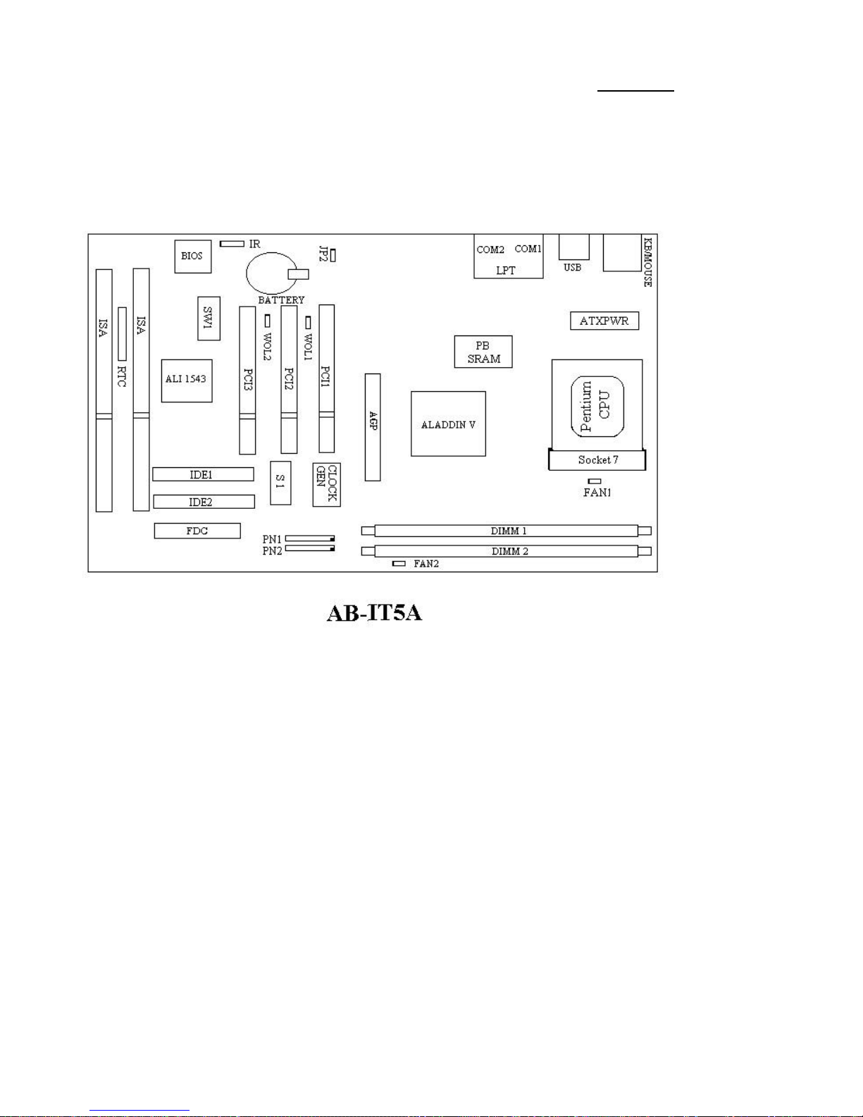
Chapter1Introduction ofIT5AFeatures
TheIT5AhasbeenespeciallydesignedforFileserver,WorkstationandProfessional
users.Itcansupportawiderangeofprocessors,includingIntelCPUs(P54C)andIntel
CPUswithMMX(P55C),aswell asall AMD-K5/K6/K63DandCyrix6x86MXCPUs.It
alsotakesintoaccount,otherfutureCPUs.
TheIT5AusesALiAladdinV(M1541 /M1543 )chipsets,andhas512KLevel-2
PipelineBurstSRAMonboard.Thismainboardisdesignedforuseat100 MHzFrontSide
Busspeeds.ItalsosupportsthelatestAGPtechnology.
Two168-pinDIMM (DualIn-LineMemoryModule)slotsmeettherequirementsfor
all memoryconfigurationsrequiredbyhighlevelcomputing.The168-pinDIMM slots
supportEDO (ExtendedDataOut)DRAMandSynchronousDRAM(SDRAM)asa
memorystandardfornextgeneration64-bitsystems.
TheIT5AalsoprovidestwoUniversalSerialBus(USB)portsandmeetsthe
ConcurrentPCIRev.2.1standard.ItsupportsIDEinterface forFastHDD (Mode0~4)
andUltraDMA/33,aswell asIDEBusMaster.Thesefeaturesalsomeetpresentand
futureinterface standardsandneeds.
SystemBIOSfeaturesincludePlug-and-Play(PnP),AdvancedConfigurationPower
Interface (ACPI),thenewestDesktopManagementInterface (DMI),aswell asIT5A’s
uniqueCPUoperatingfrequencyandvoltagesetup featureinordertomeetmodern
computingdemands.

1-2Chapter1
IT5A
nSpecifications
1.SupportsATXpowersupply
2.AdjustmentforFrequencyandVoltage:UsesaDIPswitchorjumperwirestoadjust
thefrequencyandvoltageonthemainboard
3.UsesZIFCPUSocket7foreasyCPUinstallation
SupportsswitchingpowerforamorestableenvironmentfortheCPU
SupportsIntelCPUs:
1)Pentium100,133,166,and200MHz
2)PentiumprocessorwithMMXTMtechnology166MHzto233MHz
SupportsAMDCPUs:
1)AMD-K5*PR100,PR133,andPR166.
2)AMD-K6TM166MHzto233MHz.
3)AMD-K63DTM266 to300MHz
SupportsCyrix/IBMCPUs:
1)Cyrix6x86MXTMPR166 ~PR266
SupportsIDTWinChipC6CPU:200MHz.
*ReservedcircuitrysupportsfuturesixthgenerationCPUs
4.Chipset
ALiAladdinV(M1541 .M1543 )chipset
SupportsstandardversionPCI2.1
SupportsAGP66/133 MHz(Sideband)3.3Vdevices
5.L2CacheMemory
512Kofcachememory(PipelineBurstSRAM)
6.SystemDRAM
Two168-pinDIMM sockets:supportEDO andSynchronousDRAM(SDRAM)
DIMM socketsusePCmodules(3.3VUnbufferedDRAM)
Upto256MBmemoryconfigurationpossible

IntroductionofIT5AFeatures
1-3
7.SystemBIOS
AWARDBIOS
SupportsPlug-and-Play(PnP)
SupportsAdvancedConfigurationPowerInterface (ACPI)
SupportsDesktopManagementInterface (DMI)
8.MultiI/Ofeatures
TwoUniversalSerialBus(USB)ports
TwofastIDEchannels(PIOmode0~4,Ultra“DMA/33”andBusMaster)
OnestandardEPP/ECPparallelportandtwo16550 serialports
Twofloppydiskdriveconnectors(FDD)(360K,720K,1.2M,1.44Mand2.88M
)
SupportsPS/2typemouseandkeyboard
9.Otherfeatures
StandardATXarchitecturedimensions
OneAGPslot,three PCIbusslotsandtwoISAbusslotsand
Supports3-MODEforaspecialJapanesefloppydiskdrive
Supportstwobootableharddisks--abletoruntwodifferentoperatingsystems
SupportsIDE(ATAPI)interface CD-ROM,ZIPandLS-120 typefloppydisk
drive(Bootonly)
Note:All brandnamesandtrademarksarethepropertyoftheirrespectiveowners.

1-4Chapter1
n
Layoutdiagram
Fig1-1Layoutdiagram

IntroductionofIT5AFeatures
1-5
n
Systemblockdiagram
Fig.1-2IT5ASystemblockdiagram

1-6Chapter1

InstallingtheMainboard
2-1
Chapter2Installing theMainboard
ThisIT5Amainboardnotonlycanbeusedwithall standardequipmentfor
traditionalpersonalcomputers,butalsoprovidesgreatflexibilityformeeting
futureupgradedemands.Thischapterwill introduce stepbystepall the
standardequipmentandwill alsopresent,ascompletelyaspossiblefutureupgrade
capabilities.Thismainboardisabletosupportall IntelPentiumchipsincluding
P55CwithMMX,Cyrix6x86MXandAMD-K5/K6/K6-3Dprocessorsnowon
themarket.(Fordetails,see specificationsinChapter1.)However,wecannot
guarantee thedescriptiongiveninthismanualofthecircuitryofyourmainboard
will workforprocessorsnotlistedinChapter1.Forexample,theoperating
voltageofCyrix’snextgenerationCPUisunknownatpresent.Thuswewerenot
abletoincludethesespecificationsinyourmotherboard.Wewill supplyfurther
informationaboutCPUsupportwhennewCPUsarriveonthemarket.
Thischapterisorganizedaccordingthefollowingfeatures:
ŒInstallingtheMainboardtotheCasing
•Standardexternalconnectors
ŽJumpersandswitches
•PresentationandInstallingoftheCPU.
ºInstallingthesystemmemory.
NNNN
Before proceedingwiththeinstallation
Beforeinstallingthemainboardpleasebesuretoturnoff ordisconnectthe
powersupplyunit.Beforemakinganymodificationstothehardware
configurationofthemainboard,thepowersupplytoanyareasofthemainboard
youplantomodifyshouldbeturnedoff toavoidunnecessarydamagetothe
hardware.

2-2Chapter2
&
User friendlyinstructions
Ourobjectiveistoenablethenovice computerusertoperformtheinstallation
bythemselves.Wehaveattemptedtowritethisdocumentinaveryclear,concise
anddescriptivemannertohelpovercomeanyobstaclesyoumayface during
installation.Pleasereadourinstructionscarefullyandfollowthemstep-by-step.

InstallingtheMainboard
2-3
¬
InstallingtheMainboardtotheCasing
Mostcomputercaseswill haveabaseonwhichtherewill bemanymounting
holesthatallowsthemainboardtobesecurelyattachedandatthesametime,
preventsshortcircuits.
Therearetwowaystoattachthemainboardtothebase.
withspacers
orwithbolts
Inprinciple,thebestwaytoattachthemotherboardiswithbolts,andonlyif
youareunabletodothisshouldyouattachtheboardwithspacers.Takeacareful
lookatthemainboardandyouwill see manymountingholesonit.Linethese
holesup withthemountingholesonthebase.Iftheholeslineup,andthereare
screwholesthismeansyoucanattachthemainboardwithbolts.Iftheholesline
up andthereareonlyslots,thismeansyoucanonlyattachthemainboardwith
spacers.Takethetipofthespacersandinsertitintotheslots.Afterdoingthisto
all theslots,youcanslidethemainboardintopositionalignedwiththeslots.After
themainboardhasbeenpositioned,checktomakesureeverythingisOKbefore
puttingthecasingbackon.
Note:Ifthemainboardhasmountingholes,butdon’tlineup withtheholeson
thebaseandtheirarenoslotstoattachthespacers,don’tworry,youcanstill
attachthespacerstothemountingholes.Justcutthespacers(alongthedottedline)
(thespacermaybealittlehardsobecarefulofourhands).Inthiswayyoucanstill
attachthemainboardtothebasewithoutworryingaboutshortcircuits.

2-4Chapter2
-
StandardExternalConnectors
Insidethecaseofanycomputerseveralcablesandplugshavetobe
connected.Thesecablesandplugsareusuallyconnectedone-by-oneto
connectorslocatedonthemainboard.Youneedtocarefullypayattentionto
anyconnectionorientationthecablesmayhaveand,ifany,notice thepositionof
thefirstpinoftheconnector.Intheexplanationthatfollows,wewill describe
thesignificance ofthefirstpin.
Fig2-1Externalconnectorslayout
PN2-KeylockconnectorPleasepayattention topinposition and orientation
Thisconnectorhasaspecificorientation.Connectthefive-threadkeylock
connectorcabletothePN2connectorpinsonthemainboard.
PinnumberNameorsignificance ofsignal
1+5VDC
2Noconnection
3Ground
4Keyboardinhibit Signal
5Ground

InstallingtheMainboard
2-5
The“keylockswitch”isusedtolockthecomputer’skeyboard.
Thisdisablesthekeyboardsothatunauthorizedpersonscannotuseit.
Whenthisfunctionisinuse,youwill needtousetheunlockkeyto
activatethekeyboard.
PN1-PowerON/OFF switch
Thereisnospecificorientation.Since mostcasesdonotsupportthisfeature,most
ofyoushouldignorethisinstruction.
PinnumberNameorsignificance ofthesignal
8Ground
9Poweron/off signal
PN2-SMISwitch
Thereisnospecificorientation.Connectthetwo-threadcabletothePN1
connectorpinsonthemainboard.Since mostcasesdonotsupportthisfeature,
mostofyoushouldignorethisinstruction.Furthermore,thisfeatureisnot
necessaryasitisalreadyapartofthemainboard.
PinnumberNameorsignificance ofsignal
10 SMIsignal
11 GND
PN2-HDD LEDconnector
Thisconnectorhasaspecificorientation.Connectthetwo-threadIDELED
connectorcableattachedtothecasetotheIDELEDconnectoronthemainboard.
PinnumberNameorsignificance ofsignal
6LED’sCathode
7LED’sAnode
PN1-Speakerconnector
Thereisnospecificorientation.Connectthefour-threadspeakercabletothe
PN1connectorpinsonthemainboard.
PinnumberNameorsignificance ofsignal
4+5VDC
5Ground
6Ground
7SoundSignal

2-6Chapter2
PN1-HardwareResetconnectors
Thereisnospecificorientation.Connectthetwo-threadhardwareresetcable
tothePN1connectorpinsonthemainboard.
PinnumberNameorsignificance ofsignal
1Hardwareresetsignal
2Ground
PN1-SleepLEDconnector
Thisconnectorhasaspecificorientation.Connectthetwo-threadSleepLED
connectorcableattachedtothecasetotheSleepLEDconnectoronthe
mainboard.
PinnumberNameorsignificance ofsignal
9LED’sCathode
10 LED’sAnode
FAN1-CPUFanpowerconnector
Thishasaspecificorientation.Connectthethree-threadsCPUfancabletothe
FAN1connector.
PinnumberNameofthesignalorsignification
1Controlon/off
2+12V
3Sensor

InstallingtheMainboard
2-7
ATXPWR-ATXPowerinputConnectors
Thesehaveaspecificorientation.Thethree warningmarksindicatethatifyou
makeamistakeinpinnumberorconnectionorientation,youcoulddestroyyour
equipment.Duringinstallation,youjustneedtoconnecttothecorrectpinsandin
thecorrectorientation,andtoconnectthepowersupplyunittotheconnectoron
themainboard.
PinnumberNameofthesignalor
significationPinnumberNameofthesignalor
signification
1+3.3VDC11 +3.3VDC
2+3.3VDC12 -12VDC
3Ground 13 Ground
4+5VDC14 PS_ON
5Ground 15 Ground
6+5VDC16 Ground
7Ground 17 Ground
8POWERGOOD 18 -5VDC
9+5VDC19 +5VDC
10 +12VDC20 +5VDC
Fig2-2MechanicsofMouse/Keyboard/USB/COM1/COM2/LPT

2-8Chapter2
MOUSE-PS/2MouseConnector
AttachaPS/2mousetothis6-pinDin-connector.
PinnumberNameorsignificance ofsignal
1Mousedata
2Noconnection
3Ground
4+5VDC
5Mouseclock
6Noconnection
KB-PS/2KeyboardConnector
Attachakeyboardtothis6-pinDin-connector.
PinnumberNameorsignificance ofsignal
1Keyboarddata
2Noconnection
3Ground
4+5VDC
5Keyboardclock
6Noconnection
Storagedevice connectorsWatchthepinnumberand theorientation
ConnectornamePinnumberNameoftheperipheralconnected
IDE1 40 IDEPrimaryChannel
IDE2 40 IDESecondaryChannel
FDC34 FloppyDiskconnector
Table of contents
Other Abit Motherboard manuals