Ablerex TAURUS 10 kVA User manual

TAURUS Series
10-80 kVA UPS
Installation and Operation Manual

CONTENTS
Preface...............................................................................................................................1
Safety .................................................................................................................................2
1. Function Description..............................................................................................3
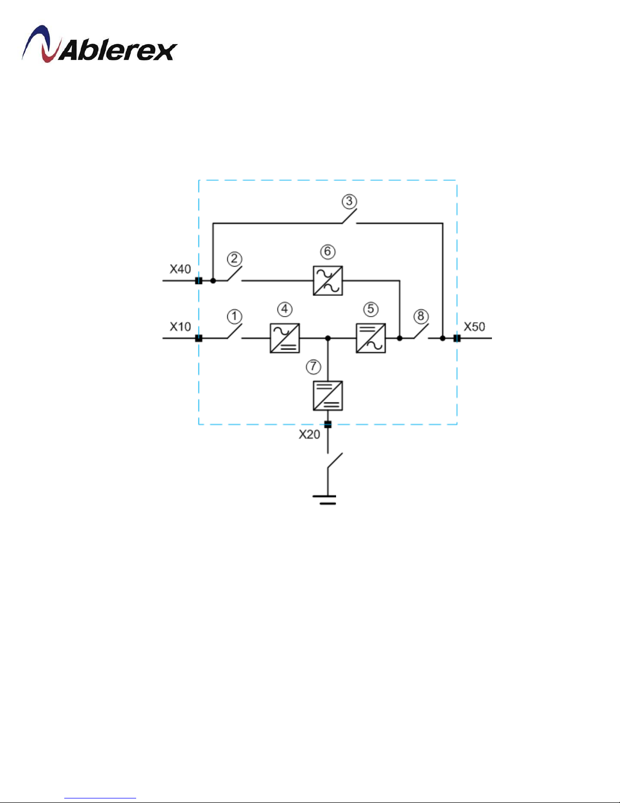
1.1 UPS Block Diagram.......................................................................................3
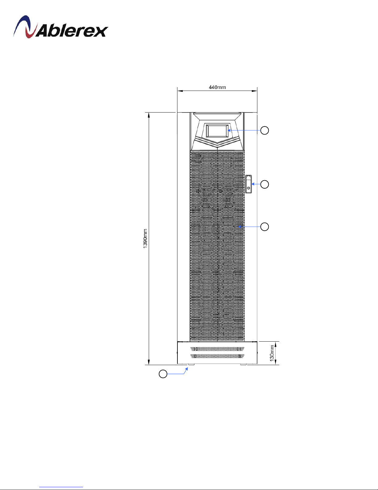
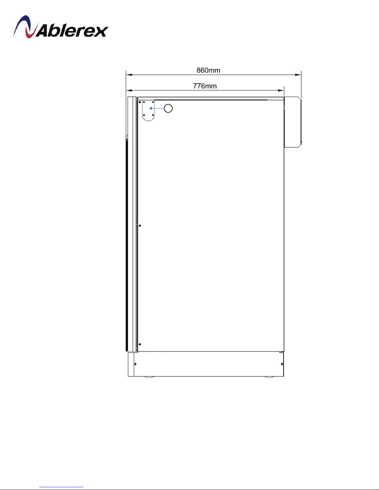
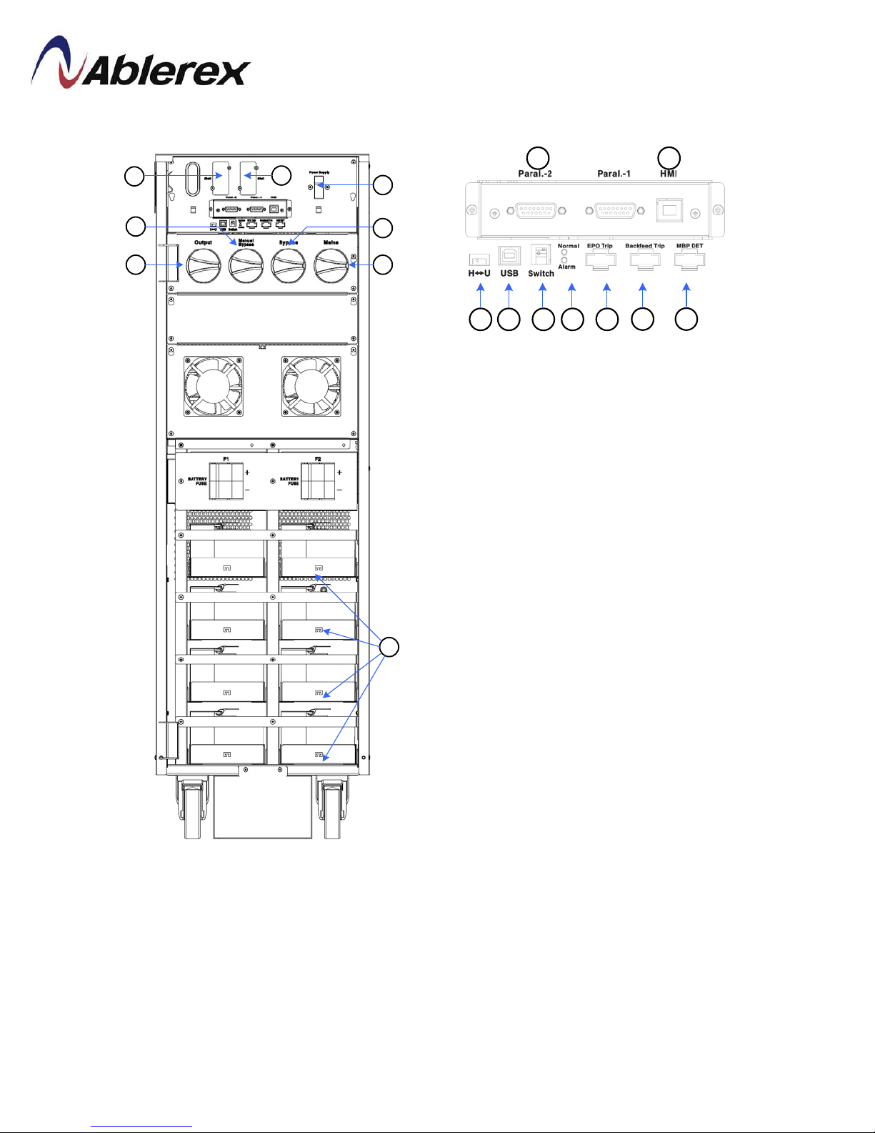
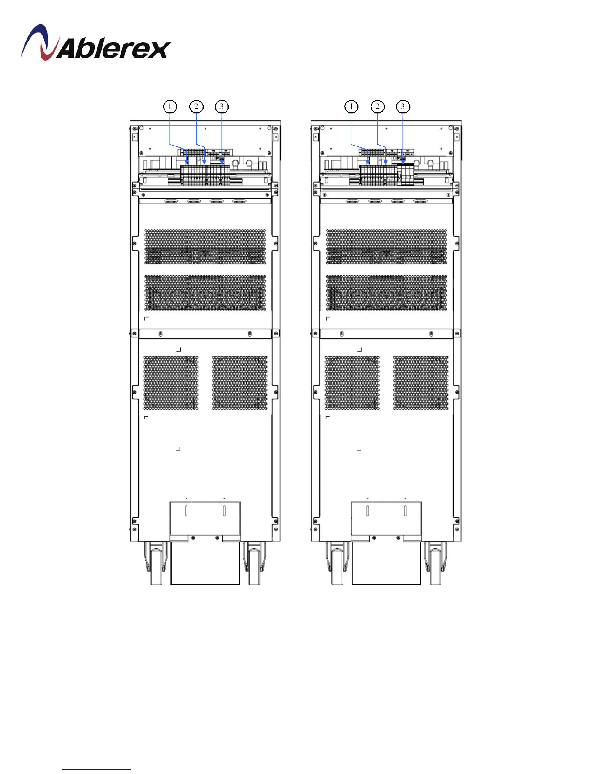
1.2 UPS Outlook View.........................................................................................4
2. Installation and Wiring........................................................................................15
2.1 Storage and Installation Environment...........................................................15
2.2 Unpacking, Removing and Fixing UPS........................................................16
2.3 General Requirement for Ventilation and Maintenance................................23
2.4 Power Cables Connections...........................................................................24
2.5 Communication Cables Connections............................................................33
2.6 UPS Parallel Connections.............................................................................37
3. Operation Descriptions........................................................................................42
3.1 Operating Mode............................................................................................42
3.2 Online Operations ........................................................................................43
3.3 Manual Bypass Operation.............................................................................43
3.4 Operation Processes .....................................................................................44
4. Control Panel Operation and Function Description ........................................47
4.1 Screen Introduction ......................................................................................47
4.2 Menu............................................................................................................48
4.3 Mimic Display..............................................................................................53
5. Options ..................................................................................................................54
5.1 Dry Contact Card .........................................................................................54
5.2 RS-485 MODBUS Card...............................................................................54
5.3 SNMP Card..................................................................................................54
5.4 Temperature Sensor......................................................................................55
5.5 DC Cold Start Kit.........................................................................................55
5.6 Parallel Communication Cable.....................................................................55
6. Troubleshooting....................................................................................................56
7. Technical Specification........................................................................................57
I 192321262008007

Preface
We thank you for the trust in selecting our UPS.
Our equipment complies with the European Community directives for professional
equipment and is authorize to use the CE marking.
The purpose of this manual is to introduce the operating principles of the UPS and to
provide instructions for its safe operation. The manual also provides troubleshooting
assistance should an abnormal message or behavior occur.
Should an abnormal message not covered in this manual appear, please contact your
local authorized service agent for troubleshooting and repair.
All of the installation, operation, and maintenance of this device must be performed
by authorized and qualified technicians who are familiar with this manual.
1 192321262008007

Safety
Important Rules
(1) Please follow these UPS operating instructions to ensure safe and proper operation.
(2) When the UPS is being moved or operated, please ensure that the machine is standing
vertically. Do not shake or tip over the machine. Avoid heavy impact.
(3) Poor grounding will lead to unexpected current leakage. Please ensure that the AC
power input is properly grounded (PE Ground) before making any connections.
(4) Please make sure that the UPS is placed in an insulated environment before use and
that there is no electrocution hazard to the operating personnel.
(5) Do not connect the neutral wire with the ground and make sure that the input voltage
is correct.
(6) Once the UPS has been switched on, if the UPS needs to be moved then it must be
fully switched off and fully discharged. If the UPS is not discharged, the UPS will
switch to battery power after grid power is disconnected and pose an electrocution
hazard.
(7) Do not place any objects, liquid containers, or coverings over the UPS. The liquid
spilt into the UPS or heat prevented from dissipating could lead to internal damage or
cause electrocution.
(8) Make sure that the battery specifications match the UPS requirements before
connecting any external batteries.
(9) Please follow the rules below before engaging in any activity that involves the battery.
a. Remove all metallic items such as rings, watches and jewelry before working on
the battery.
b. Please use insulated tools.
c. Do not open or damage the battery. The toxic liquid inside will harm the skin and
eyes.
d. Keep batteries away from fire to prevent explosion.
Symbols
Please follow the instructions and warnings on the UPS.
WARNING!Refer to the operating instructions.
WARNING!High voltage inside.
Ground
2 192321262008007

1. Function Description
1.1 UPS Block Diagram
This UPS provides Mains input and Bypass input for dual inputs application. The system
blockdiagram is shown as below.
○
1EInput Switch A○
5EInverter
A○
2EBypass Switch A○
6EStatic Switch
A○
3EManual Bypass Switch A○
7ECharger/Booster
A○
4ERectifier A○
8EOutput Switch
Load
Bypass Input
Mains Input
Battery
3 192321262008007

1.2 UPS Outlook View
10-40kVA Front View
1
2
4
3
A○
1EControl Panel with Colorful LCD Touch Screen A○
3EVentilation Grille
A○
2EHandle with Lock A○
4EWheels for Handling
4 192321262008007

10-20kVA Right Side View
1
A○
1EThrough Hole for Parallel Communication Cable
5 192321262008007

10-20kVA Internal View
10
12
14
15
13
16
17
11
12
3456789
A○
1EParallel Communication Ports
A○
2EHMICommunicationPort
A○
3E
Communication Selector for
Service only
A○
4EUSB Port for Service Only
A○
5E
Terminal Resistor Setting Switch
for Parallel Communication
A○
6EStatus LED Indictors
A○
7EEPO
A○
8EBackfeed Protection
A○
9EMBP Detector
A○
10ECommunication Card Slot1
A○
11ECommunication Card Slot2
Please find the detail descriptions of
above items on section 2-5.
A○
12EMains Input Switch A○
15EOutput Switch
A○
13EBypass Input Switch A○
16EFuse for Control Power
A○
14EManual Bypass Switch A○
17EBattery Tray (Option)
6 192321262008007

10-20kVA Rear View
10kVA 20kVA
A○
1E
X10/X40: Mains/Bypass Input
Connections Terminal
(1N, 2N, 1L3, 2L3, 1L2, 2L2, 1L1, 2L1)
A○
2E
X50: Output Connections Terminal
(3N, 3L3, 3L2, 3L1)
A○
3E
X20: External Battery Connections
Terminal(B+,N,B-)
7 192321262008007

30-40kVA Right Side View
1
A○
1EThrough Hole for Parallel Communication Cable
8 192321262008007

30-40kVA Interval View
12
14
15
13
10
16
17
11
12
3 4 5 6 7 8 9
A○
1EParallel Communication Ports
A○
2EHMICommunicationPort
A○
3E
Communication Selector for
Service Only
A○
4EUSB Port for Service Only
A○
5E
Terminal Resistor Setting Switch
for Parallel Communication
A○
6EStatus LED Indictors
A○
7EEPO
A○
8EBackfeed Protection
A○
9EMBP Detector
A○
10ECommunication Card Slot1
A○
11ECommunication Card Slot2
Please find the detail descriptions of
above items on section 2-5.
A○
12EMains Input Switch A○
15EOutput Switch
A○
13EBypass Input Switch A○
16EFuses for Control Power
A○
14EManual Bypass Switch A○
17EBattery Tray (Option)
9 192321262008007

30-40kVA Rear View
3
1
23
1
2
30kVA 40kVA
A○
1E
X10/X40: Mains/Bypass Input
Connections Terminal
(1N, 2N, 1L3, 2L3, 1L2, 2L2, 1L1, 2L1)
A○
2EX50: Output Connections Terminal
(3N, 3L3, 3L2, 3L1)
A○
3EX20: External Battery Connections
Terminal(B+,N,B-)
10 192321262008007

60-80kVA Front View
1
2
3
1
2
3
A○
1EControl Panel with Colorful LCD Touch Screen A○
3EVentilation Grille
A○
2EHandle with Lock A○
4EWheels for Handling
Wheel Type
Stationary Type
(Without Wheel)
11 192321262008007

60-80kVA Left Side View
A○
1EThrough Hole for Parallel Communication Cable
○
1 ○
1
Wheel Type
Stationary Type
(Without Wheel)
12 192321262008007

60-80kVA Internal View
A○
12EMains Input Switch A○
16EFuses for Control Power
A○
13EOutput Switch A○
17E
X20: External Battery Connection Terminals
(B+,N,B-,G)
A○
14EBypass Input Switch A○
18E
X10/X40: Mains/Bypass Input Connections Terminal
(1N, 2N, 1L3, 2L3, 1L2, 2L2, 1L1, 2L1)
A○
15EManual Bypass Switch A○
19E
X50: Output Connections Terminal
(3N, 3L3, 3L2, 3L1)
A○
1EParallel Communication Ports
A○
2EHMICommunicationPort
A○
3E
Communication Selector for
Service Only
A○
4EUSB Port for Service Only
A○
5E
Terminal Resistor Setting Switch
for Parallel Communication
A○
6EStatus LED Indictors
A○
7EEPO
A○
8EBackfeed Protection
A○
9EMBP Detector
A○
10ECommunication Card Slot1
A○
11ECommunication Card Slot2
Please find the detail descriptions of
above items on section 2-5.
○
1 ○
2
○
3
○
4
○
5
○
6
○
7 ○
8
○
9
○
10
○
12
○
13
○
14
○
15
○
17 ○
18 ○
19
○
16
○
9
Front Door
13 192321262008007

Rear Side of Front Door View
A○
1EUSBPort for Setting Software A○
4EOutput &Input Contacts
A○
2ESD Card Slot A○
5ERS-232 Port for Setting Software
A○
3EExternal Battery Temperature Connector A○
6ECommunicationPort for Remote Panel
Please find the detail descriptions of above items on section 2-5.
○
4
○
5
○
1
○
2
○
3 ○
6
14 192321262008007

2. Installation and Wiring
2.1 Storage and Installation Environment
Storage Environment
Temperature-20℃~70℃
Relative Humidity≦95%
Installation Environment
A proper installation environment not only ensures the effective operation of the UPS
but also reduces the chance of failure and extends service life. Please take the
following recommendations into account to select the most suitable environment and
reduce the likelihood of accidents.
Temperature0℃~40℃(20℃~25℃is recommended for extend batteries life time).
Relative Humidity ≦95% (without condensation)
Altitude1000m at normal power.Over 1000m above sea level, the maximum output
current must be derated by 1% every additional 100m.
This product must not be used in an environment with sparks, smoke or gas to
prevent arcing, injuryand fire hazards.
Avoid using dusty materials, volatile gases, or corrosive substances with a high salt-
content in the environment where the UPS is installed.
The installation location of the UPS should be well-ventilated. During charging, the
chemical reaction of the battery generates small amounts of gases. If there is a crack
in the battery then this may pose an environmental hazard.
Do not place in a location near a heat source as this will shorten the battery life.
Do not place outdoors and avoid direct exposure to sunlight.
Please ensure that the environment where the UPS is placed is free from animals that
may damage the wiring, such as: rats and other small animals.
Please ensure that the floor is strong enough to hold the UPS and battery. It must
keep the equipment stable to ensure that it won't suffer damage in a fall.
We recommend placing a fire extinguisher near the UPS in case of an emergency.
15 192321262008007

2.2 Unpacking, Removing and Fixing UPS
This section describes the unpacking and removing processes for wheel type.
Remove the packing materials and cut straps. Remove the cardboard box.
10-40kVA 60-80kVA
Unscrew the fasteningrail kits on the front and rear side of 10-40kVA, and right and
left side of 60-80kVA.
10-40kVA 60-80kVA
16 192321262008007

Put 2 fasteningrail kits on the pallet edge and make them steady by fastening 4 screws
in the pallet.
10-40kVA
60-80kVA
17 192321262008007

Raise 2 wheel-brakes or expansion foots for remove the UPS from the pallet.
10-40kVA
60-80kVA
Wheel-Brake
Wheel-Brake
18 192321262008007
This manual suits for next models
5
Table of contents
Other Ablerex UPS manuals

Ablerex
Ablerex 525VA User manual

Ablerex
Ablerex MSII-RT User manual

Ablerex
Ablerex VESTA PRO 1400 User manual

Ablerex
Ablerex 800L User manual

Ablerex
Ablerex BRIC30S User manual

Ablerex
Ablerex MSRT-Pro 1KVA User manual

Ablerex
Ablerex GR600 User manual

Ablerex
Ablerex 800LS User manual

Ablerex
Ablerex ARES RT-1K User manual

Ablerex
Ablerex AB-SR1000 User manual

Ablerex
Ablerex GR 650 User manual

Ablerex
Ablerex ODIN User manual

Ablerex
Ablerex 625L User manual

Ablerex
Ablerex 3 MS series User manual

Ablerex
Ablerex RacPDU-115A User manual

Ablerex
Ablerex JP-PRO XL 1000 User manual

Ablerex
Ablerex MSRT-Pro 1KVA User manual

Ablerex
Ablerex KRONOS User manual

Ablerex
Ablerex GR1200 User manual