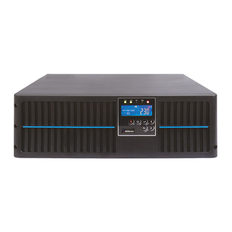
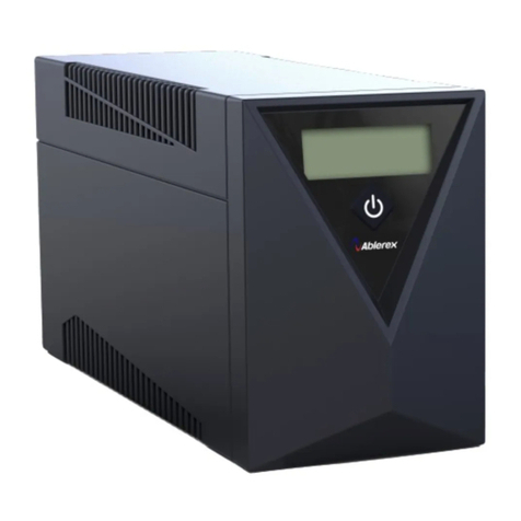
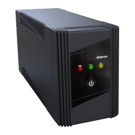
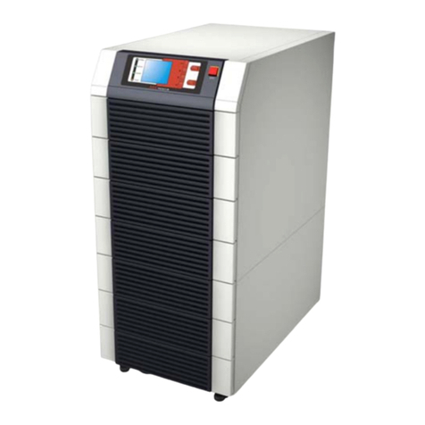
Ablerex KRONOS User manual

KRONOS 208V
10-40kVAUPS
Installation and Operation Manual

I
CONTENTS
Preface ............................................................................................................................... 1
Safety ................................................................................................................................. 2
1. Function Description .................................................................................................. 5
1.1 UPS Block Diagram .......................................................................................... 5
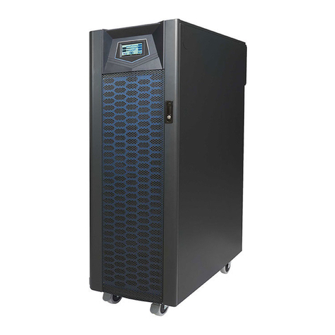
1.2 UPS Front View ................................................................................................ 6
2. Installation and Wiring ............................................................................................ 20
2.1 Storage and Installation Environment ............................................................. 20
2.2 Unpacking, Removing and Securing UPS ...................................................... 21
2.3 General Requirements for Ventilation and Maintenance ............................... 30
2.4 Power Cables Connections .............................................................................. 31
2.5 Auxiliary Power Supply Control Switch and Precharge Button ..................... 39
2.6 Communication Cables Connections .............................................................. 40
2.7 UPS Parallel Connections (Option) ................................................................ 44
3. Kronos Operation And Descriptions ...................................................................... 48
3.1 Operating Mode............................................................................................... 48
3.2 Online Operations ........................................................................................... 49
3.3 Manual Bypass Operation ............................................................................... 49
3.4 Operating Processes ........................................................................................ 50
4. Control Panel Operation and Function Description............................................. 54
4.1 Screen Introduction ......................................................................................... 54
4.2 Menu ................................................................................................................ 55
4.3 Mimic Display ................................................................................................. 60
5. Options ...................................................................................................................... 61
5.1 Dry Contact Card ............................................................................................ 61
5.2 RS-485 MODBUS Card .................................................................................. 61
5.3 SNMP Card ..................................................................................................... 61
5.4 Temperature Sensor ........................................................................................ 62
5.5 Parallel Communication Card ......................................................................... 62
6. Troubleshooting ........................................................................................................ 63
6.1 Export machine information from LCD panel ..............................................63
6.2 Exporting The event log from LCD panel.....................................................64
7. Technical Specifications ........................................................................................... 65
Appendix ......................................................................................................................... 67

1
Preface
We thank you for the trust in selecting our Kronos UPS.
The purpose of this manual is to introduce the user to the operating principles of the
Kronos UPS and to provide instructions in it's safe operation. The manual also
provides troubleshooting assistance should an abnormal message or behavior occur.
Should an abnormal message not covered in this manual appear, contact your local
authorized service agent for troubleshooting and repair.
All of the installation, operation, and maintenance of this device must be performed
by authorized and qualified technicians who are familiar with this UPS.

2
Safety
SAVE THESE INSTRUCTIONS - This manual contains important instructions that should be
followed during installation and maintenance of the UPS.
Important Rules
(1) Please follow the Kronos UPS operating instructions to ensure safe and proper operation.
(2) When the UPS is being moved or operated, please ensure that the machine is standing
vertically. Do not shake or tip over the machine. Avoid heavy impact.
(3) Poor grounding will lead to unexpected current leakage. Please ensure that the AC power
input is properly grounded (PE Ground) before making any connections.
(4) Please make sure that the UPS is placed in an insulated environment before use and that
there is no risk of electrocution hazard to any personnel.
(5) Do not connect the neutral wire with the ground and make sure that the input voltage phasing
and conductor sizing is correct.
(6) Once the UPS has been switched on, if the UPS needs to be moved then it must be fully
switched off and fully discharged. If the UPS is not discharged, the UPS will switch to
battery power after grid power is disconnected and pose an electrocution hazard.
(7) Do not place any objects, liquid containers, or coverings on the UPS. Any liquid spilled onto
the UPS could potentially lead to internal damage or high risk of electrocution.
(8) Make sure that the battery specifications match the UPS requirements before connecting any
external batteries.
(9) For 30k/40k models: The over current protection for the external battery circuit is to be
provided by others.
(10) For 30k/40k models: The maximum available fault current from the battery supply is 15 KA
minimum. The dc voltage rating of the battery supply over current protection device must be
installed near the battery supply must have a minimum rating of 250 VDC.
(11) Follow the safety guidelines below before engaging in any testing that involves the battery.
a. Remove all metallic items such as rings, watches and jewelry before working on the
batteries.
b. Always wear eye protection and use insulated tools.
c. Do not open or damage the batteries. The toxic liquid inside will harm the skin and eyes.
d. Keep batteries away from fire to prevent explosion.
(12) A readily accessible disconnect device shall be incorporated external to the equipment.
(13) For 10-20k models:
-This UPS may be provided with maximum one extension battery packs
-External DC Circuit disconnect Device shall be provided by other.
-Before installing or servicing the equipment,identify and disconnect the UPS from the
AC mains and load. The UPS contains internal batteries and may present a shock hazard
even when disconnected from the AC input branch circuit (mains).
-Any wiring, maintenance service and battery replacement, must be performed or
supervised by personnel knowledgeable about batteries and the required precautions.
-When replacing batteries, replace with the same type and number of batteries or battery
packs.
-CAUTION: Do not dispose of batteries by burning them. The batteries may explode.
3
-CAUTION: Do not open or mutilate batteries. Released electrolyte is harmful to the skin
and eyes, and may be toxic.
-CAUTION: A battery can present a risk of electrical shock and high short-circuit current
through conductive materials could cause severe burns. The following precautions should
Be observed when working on batteries:
Before installing or replacing the batteries, remove jewelry such as wristwatches and rings,
or other metal objects.
-When working on batteries should wear rubber gloves and boots. Also, must use tools
with insulated handles, and do not lay tools or metal parts on top of batteries.
Remove battery grounds during installation and maintenance to reduce likelihood of
shock. Remove the connection from ground if any part of the battery is determined to be
grounded.
Symbols
Always follow the instructions and warnings on the UPS.
WARNING!Refer to the operating instructions.
WARNING!High voltage inside.
Ground

4
NOTE
NOTE: This equipment has been tested and found to comply with the limits for a Class A
digital device, pursuant to part 15 of the FCC Rules. These limits are designed to
provide reasonable protection against harmful interference when the equipment is
operated in a commercial environment. This equipment generates, uses, and can radiate
radio frequency energy and, if not installed and used in accordance with the instruction
manual, may cause harmful interference to radio communications. Operation of this
equipment in a residential area is likely to cause harmful interference in which case the
user will be required to correct the interference at his own expense.
WARNING
WARNING: This is a category C2 UPS product. In a residential environment, this
product may cause radio interference, in which case the user may be required to take
additional measures.

5
1. Function Description
1.1 UPS Block Diagram
The system block diagram is shown below.
○
1
Input Breaker/Switch
○
5
Static Switch
○
2
Manual Bypass Breaker
○
6
Charger/Booster
○
3
Rectifier
○
7
Output Breaker
○
4
Inverter
○
8
Bypass Breaker
13 4
5
2
7
6
X20
X50X10
Mains Input
Battery
Load
Single Input
13 4
5
2
7
6
X20
X50X10
X40
8
Mains Input
Bypass Input
Battery
Load
Dual Inputs

6
1.2 UPS Front View
10kVA Front View
1
2
3
260mm
890mm
69mm
1
Control Panel with Color LCD Touch Screen
3
Wheels for Positioning
2
Ventilation Grille

7
15-20kVA Front View
3
410mm
977mm
72mm
1
2
1
Control Panel with Color LCD Touch Screen
3
Wheels for Positioning
2
Ventilation Grille

8
30-40kVA Front View
1
Control Panel with Color LCD Touch Screen
3
Wheels for Positioning
2
Ventilation Grille
○
1
○
2
○
3

9
10kVA Right Side View
850mm

10
15-20kVA Right Side View
850mm

11
30-40kVA Right Side View

12
10kVA Rear View
1 2
14
3
4
5
6
19
20
17
18
22
21
23 24
16
15
25
1. Communication Slot 1
2. Communication Slot2
3. Dry Contacts
4. External Battery Temperature Connector
5. RS-232 Port for Setting Software
6. Parallel Communication Ports(Option)
7
8
9
10
11
12
13
7. Communication Selector for
Service Only
8. USB Port for Service Only
9. Terminal Resistor Setting Switch
for Parallel Communication
10. Status LED Indictors
11. EPO
12. Backfeed Protection
13. MBP Detector
Please find the detail descriptions of above items on section 2-
6.
14. Manual Bypass Breaker
20. Output Breaker
15. Bypass Fuses
21. X40: Bypass Input Connections Terminal(2N, 2L3, 2L2,
2L1)
16. Bypass Input Breaker
22. X10: Mains Input Connections Terminal(1N, 1L3, 1L2,
1L1)
17. Mains Input Breaker
23. X50: Output Connection Terminals (3N, 3L3, 3L2, 3L1)
18.AC Power
24. X20: External Battery Connection Terminals(B-, B_N,B+)
19. Batt. Start
25. Ground Connection

13
15-20kVA Rear View
1 2
14
3
4
5
6
18
19
16
17
22
20
23 24
15
21
25 26
1. Communication Slot 1
2. Communication Slot2
3. Dry Contacts
4. External Battery Temperature Connector
5. RS-232 Port for Setting Software
6. Parallel Communication Ports(Option)
7
8
9
10
11
12
13
7. Communication Selector
for Service Only
8. USB Port for Service Only
9. Terminal Resistor Setting
Switch for Parallel
Communication
10. Status LED Indictors
11. EPO
12. Backfeed Protection
13. MBP Detector
Please find the detail descriptions of above items on
section 2-6.
14. Bypass Input Breaker
21. Batt. Fuses
15. Output Breaker
22. X10: Mains Input Connections Terminal(1N, 1L3, 1L2,
1L1)
16. Manual Bypass Breaker
23. X40: Bypass Input Connections Terminal(2N, 2L3, 2L2,
2L1)
17. Mains Input Breaker
24. X50: Output Connection Terminals (3N, 3L3, 3L2, 3L1)
18. Bypass Fuses
25. X20: External Battery Connection Terminals(B-, B_N,B+)
19. AC Power
26.Ground Connection
20. Batt. Start

14
30-40kVA Rear View
1. Communication Slot 1
2. Communication Slot2
3. Dry Contacts
4. External Battery Temperature Connector
5. RS-232 Port for Setting Software
6. Parallel Communication Ports(Option)
7. Communication Selector for Service Only
8. USB Port for Service Only
9. Terminal Resistor Setting Switch for Parallel
Communication
10. Status LED Indictors
11. EPO
12. Backfeed Protection
13. MBP Detector
Please find the detail descriptions of above items on
section 2-6.
14. Bypass Input Breaker
20. X20: External Battery Connection Terminals(B-,
B_N,B+)
15. Output Breaker
21. X10: Mains Input Connections Terminal(1N, 1L3,
1L2, 1L1)
16. Manual Bypass Breaker
22. X40: Bypass Input Connections Terminal(2N, 2L3,
2L2, 2L1)
17. Mains Input Switch
23. X50: Output Connection Terminals (3N, 3L3, 3L2,
3L1)
18. AC Power
24.Ground Connection
19. Batt. Start
14
15
16
17
21 22 23 24
18
19
20
7 8 9 10 11 12 13

15
10kVA Internal Right View
1
1.
Battery Tray

16
15-20kVA Internal Right View
1
1.
Battery Tray

17
10kVA Internal Top View
1.
SD Card Slot
2.
Jumpers (J1~J3) for each output
contact
The detailed descriptions of the above items are located in section 2-6.
○
1
○
2

18
15-20kVA Internal Top View
1.
SD Card Slot
2.
Jumpers (J1~J3) for each output
contact
The detailed descriptions of the above items are located in section 2-6.
○
1
○
2
Table of contents
Other Ablerex UPS manuals

Ablerex
Ablerex AB-SR1000 User manual

Ablerex
Ablerex ARES RT-1K User manual

Ablerex
Ablerex VESTA PRO 1400 User manual

Ablerex
Ablerex GR600 User manual

Ablerex
Ablerex MSRT-Pro 1KVA User manual

Ablerex
Ablerex JP-PRO XL 1000 User manual

Ablerex
Ablerex 800L User manual

Ablerex
Ablerex 3 MS series User manual

Ablerex
Ablerex 625L User manual

Ablerex
Ablerex BRIC30S User manual

Ablerex
Ablerex 525VA User manual

Ablerex
Ablerex GR1200 User manual

Ablerex
Ablerex MSII-RT User manual

Ablerex
Ablerex 800LS User manual

Ablerex
Ablerex TAURUS 10 kVA User manual

Ablerex
Ablerex ODIN User manual

Ablerex
Ablerex MSRT-Pro 1KVA User manual

Ablerex
Ablerex RacPDU-115A User manual

Ablerex
Ablerex GR 650 User manual