21
EN
Safety notices for using the product
All parts and assemblies were developed and built
according to recognised safety-related rules. Nevert-
heless, improper use or handling may lead to hazards
for the user or third parties on the product or other
assets.
The product may only be used:
• As intended.
• In safe and proper technical condition.
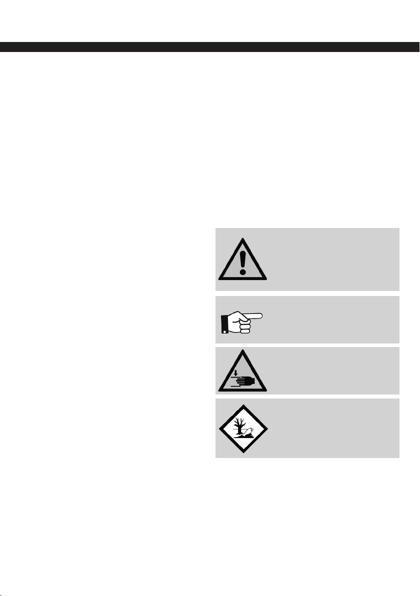
Specic hazards
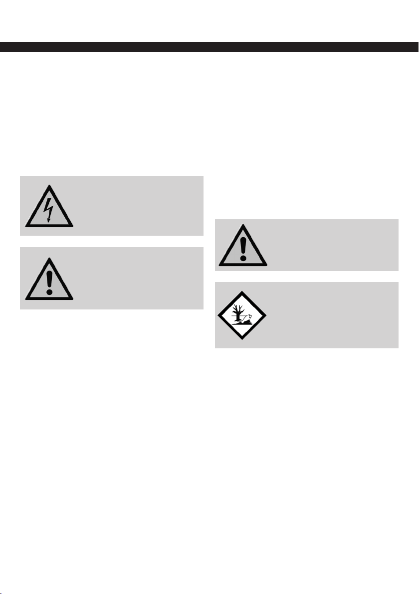
ELECTRICAL VOLTAGE
Warning of electrical hazards that
may lead to physical injury and/or
damage to property.
HYDRAULIC AND PNEUMATIC
SYSTEMS
Warning of hydraulic and pneumatic
hazards that may lead to physical
injury and/or damage to property.
Hazards due to hydraulic and pneumatic energy
Depending on the version, the product works with
high hydraulic or pneumatic pressure (see techni-
cal data). Sections of the system that need to be
opened, such as pressure lines, valves or loads, have
to be de-pressurised before the start of repairs. No
residual pressure is permitted to remain.
Hazard due to electrical voltage
Contact with live components may cause death.
• Turn off the energy supply and secure it against
reconnection prior to assembly, adjustment and
maintenance tasks.
• The electrical connection may only be established
by a licensed electrician.
• Live components have to be covered.
Hazards due to lubricants
The safety notices and instructions of the lubricant
manufacturer have to be observed and followed.
The manufacturer of this product assumes no liability
whatsoever for incidents caused the failure to obser-
ve the provisions, instructions and recommendations
of the lubricant manufacturer.
Maintenance, upkeep and
troubleshooting
• Prescribed adjustment and maintenance tasks
according to the maintenance schedule have to be
carried out in a timely manner.
• Inform the operating personnel about adjustment
and maintenance task.
• The master switch (if any) has to be turned off.
• Disconnect the energy supply from the network and
secure it against unintentional reconnection.
• Pneumatic and/or hydraulic systems must be
de-pressurised.
• Check all threaded connections and ttings for
tightness.
• All safety devices and operating functions have to
be checked after completion of the work
CAUTION
The product always has to be shut
off prior to all work.
ENVIRONMENTAL HAZARDS
The various materials/liquids have to
be handled properly and disposed
of separately according to the
respective applicable national
regulations.
Warranty and liability
Warranty and liability claims for personal injury and
damage to property are excluded when they are due
to one or more of the following causes:
• Improper use of the product.
• Worked carried out by other than qualied person-
nel.
• Improper transportation, storage, assembly,
commissioning, operation and maintenance of the
product.
• Failure to observe the information in the operating
manual regarding safety, transportation, storage,
assembly, commissioning, operation, maintenance
and setup of the product.
• Operating the product with defective protective de-
vices or improperly installed or non-functional safety
and protective devices.
• Structural changes to the product.
• Changing the compression ratios for pressure
protection, and operating at pressures higher than
intended for the product.