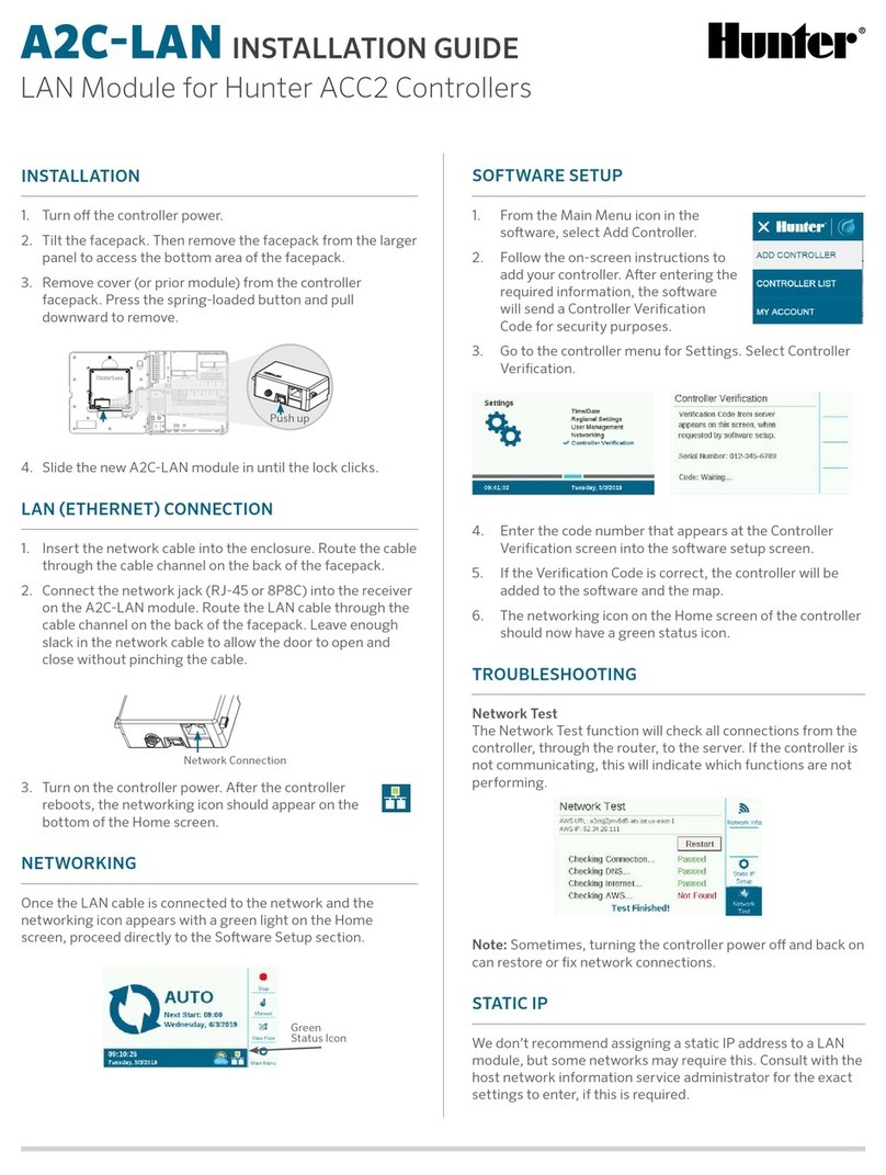
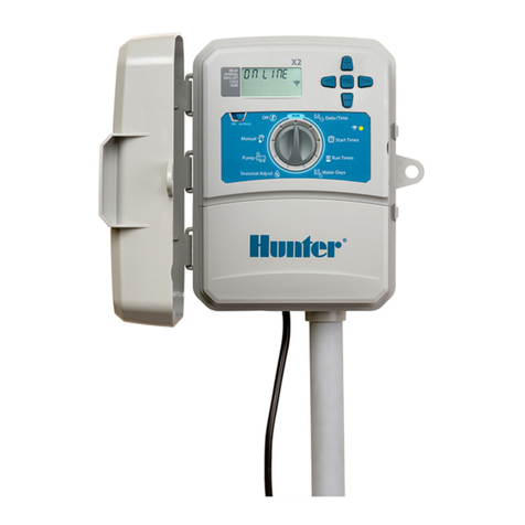
Hunter A2C-LTE User manual

A2C-LTE AND A2C-CELL-E
Installation Guide
Cellular Communication Modules
for Hunter ACC2 Controllers

PREPARATION
The A2C-LTE cellular communication module
is designed for use in North America. The
A2C-CELL-E cellular communication module
is designed for use in other parts of the world.
Each module includes a pre-registered SIM card
for use in Hunter controllers only. The card will
not work in other devices.
This SIM card requires a service plan. The
controller setup process will include simple
steps for entering secure billing and payment
information.
If your organization requires you to use
a different plan or account, the SIM card
must be replaced with one supplied by your
organization. You will be required to enter
the Access Point Name (APN) used by your
organization in the controller setup screens.
The original ACC2 facepack could not support
a cellular module. If the controller detects an
incompatible cell module, a warning message
will appear in the controller display, as shown
at right.
If the module will be used to connect
the controller to the internet, a Hunter
Centralus™ account is required to
complete final controller configuration
in the software application. Visit
centralus.hunterindustries.com to set up
a free Hunter account in advance, so your
installation can be completed and tested.
!

INSTALLATION
Turn off the controller power using the power
switch on the transformer.
Module Installation
Remove the dust cover, or existing module,
from the bottom rear of the controller facepack.
Push up on the spring-loaded button and pull
downward to remove.
Push up
Slide in the new module until the lock clicks.
SIM Card Replacement
The module includes a tool for SIM card removal
or installation. This tool is normally only used
when changing from the Hunter-supplied SIM
to a local SIM.
1. Remove the tool from the receptacle on the
module
2. Insert it in the SIM card slot (domestic
and international SIM slots are in slightly
different locations). Gently press on the
SIM with the tool and release. The SIM will
eject partially. The tool can also be used to
remove the SIM card if necessary.
3. Before inserting a new SIM, verify the
correct orientation of the SIM as indicated
by the icon on the product. Load the SIM
card into the tool and push it gently into the
slot until it clicks into place.
➊ ➋ ➌

Antenna Installation
Plastic controllers: Carefully drill a ½" (13 mm)
hole in the top of the plastic wall mount,
where indicated by the printed circle on top
of the controller. Remove all plastic debris
left behind after drilling.
Remove the nut from the antenna assembly.
Route the antenna cable through the hole and
the nut. Apply RTV sealant around the hole,
filling the gap between the enclosure hole and
the mounting threads. Tighten the nut securely.
Route the antenna cable through the track on
the back of the doorframe to the module in
the facepack. Leave just enough slack to allow
the door to open and close without pinching
the cable.
Connect the cable to the module and tighten
by hand.
Existing metal enclosures: The antenna
must be installed outside the controller
enclosure on a metal bracket. Do not drill
the enclosure directly.
These installations require a Hunter model
10010100 wall bracket to complete the
installation.
The antenna includes approximately 9' (2.8 m)
of cable. Choose a bracket mounting location
that will allow the antenna cable to be routed
through conduit to the openings in the bottom
of the controller, and then through the track on
the doorframe to the cellular module.
Mount the bracket as high as possible to the
wall with mounting hardware appropriate for
the mounting surface.
10010100

Route the antenna cable through the hole in
the bracket. Install the antenna on the bracket
with the nut. Tighten the nut securely.
Route the cable from the bracket through
conduit down, over, and into the controller
enclosure via the conduit holes in the bottom
of the enclosure.
Route the antenna cable through the track on
the back of the doorframe to the module in
the facepack. Leave just enough slack to allow
the door to open and close without pinching
the cable.
Connect the cable to the module and tighten
by hand.
Future metal controllers (available late 2020):
Metal controllers will include a hole plug
assembly in a pre-drilled factory hole on top of
the controller. Remove the nut on the inside of
the controller to remove the plug.
Route the cable through the pre-drilled hole
and the antenna nut. Then tighten the nut on
the antenna securely.
Apply RTV sealant around the hole, filling
the gap between the enclosure hole and the
mounting threads.
Route the antenna cable through the track on
the back of the door frame to the module in
the facepack. Leave just enough slack to allow
the door to open and close without pinching
the cable.
Connect the cable to the module and tighten
by hand.

Plastic pedestal: Plastic pedestal mounting
requires a Hunter model 10010000 plastic
pedestal lid adapter.
Route the antenna cable through the hole in
the bracket. Secure the antenna to the
mounting bracket with the supplied nut.
Use the included screws to install the bracket
so the antenna protrudes into the recess in the
pedestal lid, as shown.
Install the plastic cable guides as shown to
secure the antenna cable and prevent it from
pinching the cable when the lid is closed.
Route the cable down the hole to the side of the
facepack frame. Connect it to the connector on
the LTE module.
Do not allow any metal portion of the
antenna cable to touch metal or earth
ground with the power on.
Turn on the controller power. After the
controller reboots, the networking icon should
appear on the bottom of the Home screen.
!
10010000

The status icon will appear red until the module
is connected to a cellular service. It should
connect automatically within a few minutes,
if a qualifying cell tower is within range. The
connected icon will appear green.
The physical installation is now complete.
Centralus software setup and cellular
billing subscription should be completed
within seven days of module connection.
The following section describes how to set up
the cellular service and add the controller to
Centralus software. This process should be
completed by the controller owner, who will
need to enter billing and payment information
for the cellular data service.
!
CONFIGURATION AND CONNECTION
Press the Main Menu button, and turn the dial
to the Settings menu. Push the dial to select.
Dial down to the Networking selection and
select it by clicking in the dial.
Connection status icon
The Networking screen will display information
about the cell module, including connection
status and the device’s serial number.
Access Point Name (APN): The access point
name tells the module where to connect for
data purposes.
• zipitwireless.com.attz will be pre-selected
for most users in North America.
• International users should press the Edit
APN soft key and select aws.inetd.gdsp
from the menu that appears.

If you plan to use these recommended Hunter
data services, you may skip the next section
and proceed directly to Software Setup.
Using a different service provider: Customers
who plan to use their own service and SIM
card will need to change the SIM card (see
the Installation section for SIM insertion), and
then change the APN to the service that the
organization’s cell provider specifies.
Press the soft key to Edit APN. A list of APN
options will appear. Use the dial to scroll down
to Manual Entry and click the dial to select it.
The keyboard entry screen will appear. Use the
keyboard to enter the APN exactly as specified
by your organization. Press the Symbols
soft key to find periods, slashes, and other
punctuation marks as needed.
When the new APN is complete, review it to
make sure the information is correct. Turn the
dial to Done on the keyboard, and select it.
The screen will return to the Network Info
page, and show the new APN. The module is
now ready to connect in the software.

Use an internet-connected computer or mobile
device to go to centralus.hunterindustries.com.
SOFTWARE SETUP
To add the controller to Centralus, go to your
Centralus account. You must have a free
Hunter account to add a controller.
From the Main Menu icon in the software,
select Add Controller.
Type a name for the controller, and the 10-digit
serial number from the A2C-LTE or A2C-CELL-E
module.
The serial number is printed on the module, and
is also visible on the controller’s Network Info
screen. Enter all zeroes that are included in the
serial number and click Next.
Enter a valid address for the controller location,
and choose the connection type. You must
select “Cellular” or you will be unable to
complete the setup successfully.
The setup process will continue to the billing
and activation screen via Hunter’s secure, third-
party cellular service provider. You will return to
the setup process when this step is complete.

Follow the on-screen instructions to set up
billing and payment. When the billing process
is complete, click to continue with controller
setup.
Enter the controller address. The address
must be a valid address in Google Maps™ to
be accepted. Press Next.
The controller will now be sent a Controller
Verification Code for security purposes.
FIRMWARE VERIFICATION
Go to the controller menu for Settings, and
select Controller Verification. You must select
the Controller Verification screen before
pressing Next, or the code will not be sent (the
software must detect the correct screen in the
display before sending the code).
Enter the code number that appears on the
Controller Verification screen into the software
setup screen.
CONTROLLER VALIDATION SUCCESS!
Control Setup successful!
You can start managing
your controller. Click on the
button below to continue.
CONTINUE
Google Maps is a trademark of Google LLC.

COMPLIANCE AND APPROVALS
Hunter Industries hereby declares that this product is in
compliance with the essential requirements and other
relevant provisions of Directive 2014/53/EU (Radio
Equipment Directive).
FCC Notice
This equipment generates, uses, and can radiate radio
frequency energy and, if not installed and used in
accordance with the manufacturer’s instruction manual,
may cause interference with radio and television reception.
This equipment has been tested and found to comply with
the limits for a Class B digital device, pursuant to part 15
of the FCC Rules. Operation is subject to the following two
conditions:
1. This device may not cause harmful interference.
2. This device must accept any interference received,
including interference that may cause undesired
operation.
The FCC regulations provide that changes or modifications
not expressly approved by Hunter Industries could void
your authority to operate this equipment. These limits are
designed to provide reasonable protection against harmful
interference in a residential installation. However, there is
no guarantee that interference will not occur in a particular
installation. If this equipment does cause harmful
interference to radio or television reception, which can be
determined by turning the equipment off and on, the user
is encouraged to try to correct the interference by one or
more of the following measures:
• Reorient or relocate the receiving antenna.
• Increase the separation between the equipment and
receiver.
• Connect the equipment into an outlet on a circuit
different from that to which the receiver is connected.
If the Verification Code is correct, the controller
will be added to the software and the map.
The networking icon on the Home screen of the
controller should now have a green status icon.
TROUBLESHOOTING
Signal Strength
The maximum signal strength value is -51 dBm. The
signal strength is shown in the upper-right corner of the
Networking screen. The closer the number is to zero, the
better the signal.
Generally, a signal of -85 dBm is adequate for reliable
communications. Readings of -99 dBm or higher will be
unreliable. Signal strength can be improved by elevating
the antenna location with an external bracket (504494),
and/or by ensuring that the antenna is not shielded by
heavy metal objects or excessive foliage.
For complete setup information, scan the QR code or visit
hunterindustries.com.
hunter.direct/centralushelp

• Consult the dealer or an experienced radio/TV
technician for help.
This device complies with Industry Canada license-exempt
RSS standard(s). Operation is subject to the following two
conditions:
1. this device may not cause interference, and
2. this device must accept any interference, including
interference that may cause undesired operation of
the device.
Le présent appareil est conforme aux CNR d’Industrie
Canada applicables aux appareils radio exempts de licence.
L’exploitation est autorisée aux deux conditions suivantes:
1. l’appareil ne doit pas produire de brouillage, et
2. l’utilisateur de l’appareil doit accepter tout brouillage
radioélectrique subi, même si le brouillage est
susceptible d’en compromettre le fonctionnement.
Changes or modifications not expressly approved by
Hunter Industries could void the user’s authority to
operate this device. If necessary, consult a representative
of Hunter Industries Inc. or an experienced radio/television
technician for additional suggestions.
To satisfy FCC RF Exposure requirements for mobile and
base station transmission devices, a separation distance
of 8" (20 cm) or more should be maintained between
the antenna of this device and persons during operation.
To ensure compliance, operation at closer than this
distance is not recommended. The antenna(s) used for
this transmitter must not be co-located or operating in
conjunction with any other antenna or transmitter.
Innovation, Science and Economic Development Canada
(ISED) Compliance Notice
This device contains licence-exempt transmitter(s)/
receiver(s) that comply with Innovation, Science and
Economic Development Canada’s licence-exempt RSS(s).
Operation is subject to the following two conditions:
• This device may not cause interference, and
• This device must accept any interference, including
interference that may cause undesired operation of
the device.
Le présent appareil est conforme aux CNR d’Innovation,
Sciences et Développement économique Canada
applicables aux appareils radio exempts de licence.
L’exploitation est autorisée aux deux conditions suivantes:
L’appareil ne doit pas produire de brouillage, et
L’utilisateur de l’appareil doit accepter tout brouillage
radioélectrique subi, même si le brouillage est susceptible
d’en compromettre le fonctionnement.
Certificate of Conformity to European Directives
Hunter Industries declares that the irrigation
controller complies with the standards of
the European Directives of “electromagnetic
compatibility” (2014/30/EU), “low voltage”
(2014/35/EU) and “radio equipment”
(2014/53/EU).
This symbol means the product must not be
discarded as household waste and should be
delivered to an appropriate collection facility
for recycling. Proper disposal and recycling
help protect natural resources, human health,
and the environment. For more information
on disposal and recycling of this product,
contact your local municipality, disposal service, or the
shop where you bought this product.
© 2020 Hunter Industries Inc. Hunter, the Hunter
logo, and all other trademarks are property of Hunter
Industries, registered in the U.S. and other countries.
RC-004-IG-A2CLTE EN 5/20
This manual suits for next models
1
Table of contents
Other Hunter Control Unit manuals

Hunter
Hunter I-40 User manual

Hunter
Hunter Hydrawise WAND User manual
Hunter
Hunter Hydrawise WAND User manual

Hunter
Hunter DUAL 48M Operating instructions

Hunter
Hunter ACC-COM-LTE User manual

Hunter
Hunter PCM-1600 User manual

Hunter
Hunter HYDRAWISE X2 User manual

Hunter
Hunter A2C-LAN User manual

Hunter
Hunter WVOM User manual
Hunter
Hunter WVL-100 User manual