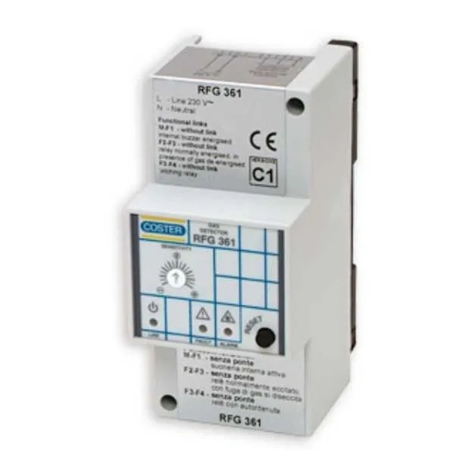
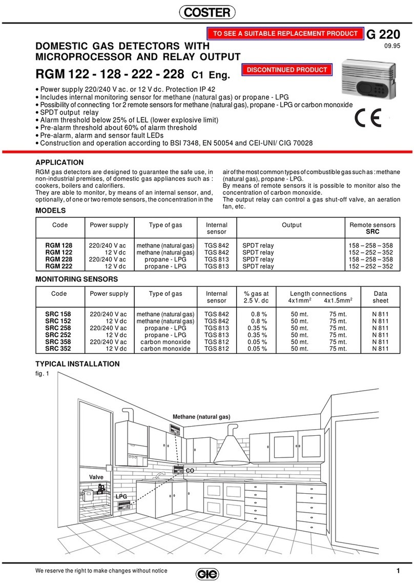
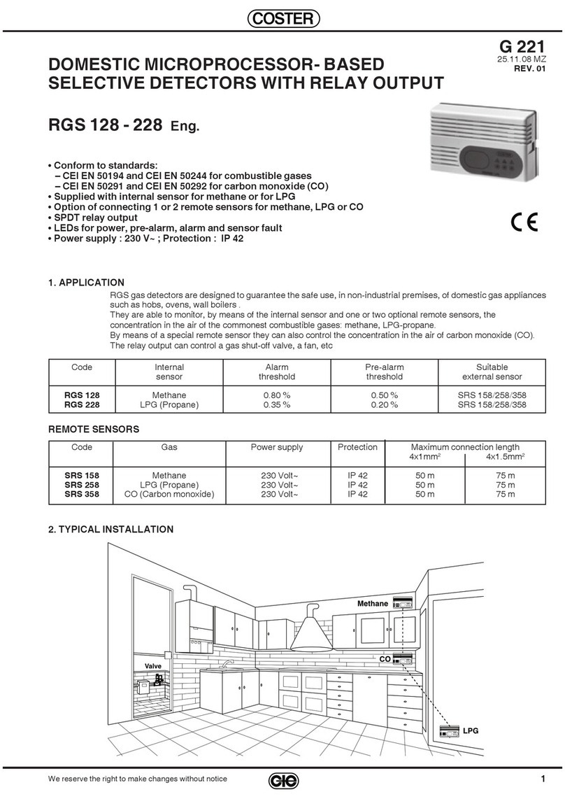
Coster RGS 328 User manual

1
G 227 - RGS 328 Eng.
25.11.08 MZ
REV. 01
We reserve the right to make changes without notice
COSTER
CARBON MONOXIDE (CO) DETECTOR
WITH RELAY OUTPUT
G 227
25.11.08 MZ
REV. 01
RGS 328
Eng.
2. TYPICAL INSTALLATION
•
Conforms to
CEI EN 50291 & CEI EN 50292
standards
•
Incorporates internal sensing element of electrochemical cell type
•
LEDs for power supply, pre-alarm, alarm & sensing element fault
•
SPDT relay output
•
Power supply
230 V~ ; protection IP 42
3. TECHNICAL DATA
Power supply
230 V ~ ± 10%
Frequency
50…60 Hz
Consumption
2,5 VA
Protection
IP 42
Electromagnetic compatibility
CEE 93/68
Ambient temperature
:
–
operating
0…40 °C
–
storage
– 20…+ 60 °C
Permitted ambient humidity
classe F DIN 40040
Weight
250 g
Output SPDT relay
:
– type stagno a gas inerte
–
maximum switching voltage
250 V ~
–
maximum switching current
5 (1) A
Acoustic alarm
85 db / 1 meter
Sensor stabilisation time
120 s
Sensing element
:
–
electrochemical cell
Sixth-Sense ECO-Sure/2e
Alarm & pre-alarm thresholds
:
– alarm "
threshold + time
"
< 50 ppm: no alarm
50…100 ppm: 60 minutes
100…300 ppm: 10 minutes
> 300 ppm:
immediate alarm
– pre-alarm
time between exceeding
threshold and alarm
1. APPLICATION
Carbon monoxide (CO) is undoubtedly one of the most toxic gases for the human body. Its danger, moreover,
is compounded by the fact that it is odourless, colourless and non-irritating and so absolutely undetectable by
human senses.
The RGS 328 detector is able to detect the presence of carbon monoxide in the air and can, therefore, ensure the
safety of persons in domestic spaces where there are gas appliances.
An output relay can activate devices for changing the air and turning off, where possible, the combustion (e.g. by
closing a shut-off valve for appliances operating on combustible liquids or gases).

2
G 227 - RGS 328 Eng.
25.11.08 MZ
REV. 01
We reserve the right to make changes without notice
COSTER
7. SITING
C
arbon monoxide (CO) is produced by the combustion of carbonaceous materials: solids (e.g. carbon, coke); liquids
(e.g. crude oil) or gaseous (e.g. methane, propane-LPG). Various types of gas appliances are normally installed
in domestic premises:e.g. fireplaces, stoves, gas hobs, ovens, water heaters, etc. Lack of or poor maintenance of
the appliances and, above all, of the means of removing the exhaust gases, can create the formation or the return
of carbon monoxide in the spaces themselves, thereby creating an extremely dangerous situation for the persons
present in them.
Large quantities of carbon monoxide are also present in the exhaust gases of automobiles, so that it is important to
check the presence of this gas in public or private garages.
The correct positioning of the gas detector is vital for ensuring its correct operation and, consequently, for
ensuring the safety of the persons present. For this reason you are advised to have the installation carried
out by qualifi ed persons.
Carbon monoxide is a gas with a density very similar to that of air so that it tends to diffuse uniformly.
The detector must be positioned:
–
at a height of 150…200 centimetres from the floor (at eye level).
–
as far as possible from kitchen gas appliances (also in order to avoid contamination of the sensor by
grease and kitchen vapours)
–
at a horizontal distance not less than 2…3 metres from gas boilers or calorifiers
.
The detector must not be positioned
:
–
in the open
;
–
in closed spaces (e.g. behind a curtain, in a corner or in a wardrobe);
–
directly above or below a basin or sink;
–
near doors or windows
;
–
near air extractors
;
– i
n places where the temperature and humidity could be at
variance with those indicated under
3. TECHNICAL DATA
;
–
in places where dust or dirt could block and so render ineffective the sensor
;
–
in places where air movement could be hindered by furniture
;
–
in places where it might be sprayed by water
;
–
in places where it would be especially difficult to reach for checking
.
6. CONSTRUCTION
The detector comprises
:
– Shockproof plastic base (4.
1
, 5.
1
) with two screw-holes at standard spacing (5
.
3
), which permit installation on a
wall or on a standard pattress, and the knockout (5.
4
) for the passage of the electric cables.
– electronic circuit (5.
2
), constructed according to CEI standards, where are housed the terminal block for the
electrical connections (5.
9
and 5.
10
); the gas-detecting sensor (5.
11
); the acoustic alarm (5.
12
); the hermetically-
sealed output relay with its contacts enclosed in inert gas to avoid the sparks from switching coming into contact
with the surrounding atmosphere (5.
8
); the push button for switching off the internal acoustic alarm and the TEST
for the device (4.
6
, 5.
15
); the microprocessor (5.
14
); the LEDs (5.
13
).
– protective cover (4.
2
), in shockproof plastic, which is secured by means of two hinge elements (5.
5
) situated on
the left; and by a cover securing clip (5.
6
) on the right.
4. OVERALL DIMENSIONS
5. BASE
1 – Base
2 –
Cover
3 –
Sensor fault LED
4 –
Alarm & pre-alarm LED
5 –
Power supply LED
6 –
Button for TEST and for
switching off
the internal
acoustic alarm
1 – Base
2 –
Printed circuit
3 –
Holes for fixing screws
4 –
Entry for cables
5 –
Cover hinge elements
6 –
Cover securing clip
7 –
Transformer
8 –
Output relay
9 –
Power supply terminal block
1
0 –
Terminal block operations
(relay switch)
11 –
Gas detecting sensing
element
12 –
Acoustic alarm
13 – LEDs
14 –
Microprocessor
15 –
Button for TEST and
switching off
internal
acoustic alarm

3
G 227 - RGS 328 Eng.
25.11.08 MZ
REV. 01
We reserve the right to make changes without notice
COSTER
8. ELECTRICAL CONNECTIONS
IMPORTANT
:
The detection system must always be in operation and so the electric power must come directly from
the mains supply without the interposition of switches or other devices which could inadvertently
render it inactive
.
For the electric wiring use 1.5 mm
2
section cables
.
9. WIRING DIAGRAMS
Warning:
RGS 328 detector is not fi tted with an alarm latching device so that it cannot be used to control
Normally-closed gas shut-off valves.
B1 –
Internal sensor of detector
M –
Air extract fan
Y1 –
Normally-open solenoid valve with manual reset
Y2 –
Normally-closed solenoid valve with manual reset
Control of an air extract
fan
Control of an air extract
fan
and a normally-open valve
with manual reset
Control of an air extract
fan
& of a normally-closed valve
with manual reset
10. OPERATION
10.
1
Switching on
The detector does not acquire, and therefore does not signal, alarms for the first two minutes of operation.
This is the time necessary for the gas sensing element to reach full working order and become stabilized so that the
reading can be considered correct and reliable.
During this period the green LED (4.
5
), which indicates the presence of power, lights intermittently; after this
stabilization period the green LED remains lit and the detector is ready for the detection of the gas.
Signalling a normal situation
The power supply LED (green) must be lit, whilst the LEDs for signalling a fault (yellow) and pre-alarm-alarm (red)
must be unlit.
The acoustic alarm must be off and the output relay switched off.
10.
2
Preallarm and alarm thresholds for carbon monoxide CO
The danger of carbon monoxide does not lie in its infiammability or potential explosiveness, but in its high toxicity.
Moreover, its danger does not depend only on the concentration of gas in the air but also on the length of time a
person remains in an atmosphere in which this gas is present.
For this reason there are different ways in which the detector can act, that is:
—
concentration <0.005% (50 ppm): the safety of the persons present is ensured for an indefinite time
and so the detector takes no action
—
concentration 0.005…0.01% (50…100 ppm): within this concentration range the sensor and the detector for 60
minutes signal a “pre-alarm” situation; when this period has elapsed
they pass to the “Alarm” condition.
—
concentration 0.01…0.03% (100…300 ppm): within this concentration range the sensor & the detector
for 10 minutes signal a “pre-alarm” situation; after this period has
elapsed they pass to the “Alarm” condition
—
concentration >0.03% (300 ppm): the safety of the persons present is not guaranteed. The sensor and the
detector immediately signal the “Alarm” condition.

4
G 227 - RGS 328 Eng.
25.11.08 MZ
REV. 01
We reserve the right to make changes without notice
COSTER
The values for concentration and exposure time taken into consideration by the sensor and, consequently, by the de-
tector, have been established allowing a large safety margin in order to ensure the safety of the persons involved.
The response of the sensor is of the “Dynamic” type: if the concentration passes from one band to another, the
time count increases or decreases as a consequence, modifying the response of the detector.
If the concentration of gas should return below 0.005% (50 ppm) for more than one minute, the detector
returns to the “Normal” condition, thereby cancelling all the times counted up to that moment.
10.
3
Signalling pre-alarm and alarm
When the detector enters “Pre-alarm” (exceeding the pre-established threshold), the red LED of the detector (4.
4
)
starts to flash.
When the detector enters the “Alarm” state (at the end of the programmed time for exceeding the threshold), the
red LED lights and stays lit, the internal acoustic alarm is switched on and the output relay is switched on.
10.
4
Switchnig off internal buzzer
When the detector is in the alarm state, press the TEST button – silence for about two seconds: the internal buzzer
is switched off (to remove the annoyance), but the detector remains in the alarm state (alarm LED lit and relay
switched on)
.
10.
5
Sensor fault and signalling this
The detector is able to signal a possible fault in the sensing element: this possibility is indicated by the flashing of
the yellow LED on the facia.
11.
PERIODIC MAINTENANCE
To ensure the continuous operation of the detector it is necessary to check its operation at least once every
three or four months according to the instructions in 11.
1
and 11.
2
below.
At least once a year, a check by a specialist technician is advisable.
11.
1
Check detector (TEST)
Keep the TEST button (4.
6
& 5.
15
) pressed for about 5 seconds until the detector enters the pre-alarm condition
and then that of alarm. Check that
:
–
the red LED lights and stays lit indicating presence alarm
–
the internal acoustic alarm is switched on
,
–
the external switch is switched on (relay switched on)
.
Release the
push-button
:
–
after about 5 seconds the alarm ceases and the detector returns to its normal operating condition
,
–
if the detector is connected to a solenoid valve with manual reset, it is necessary to re-open it with the reset le-
ver
.
11.
2
Life cycle of sensing element
On the cover of the detector is a plate showing the date of the last servicing.
After this date the life cycle of the sensing element comes to an end and the element must, therefore, be replaced
by a new one. It is necessary to carry out the calibration of the new sensing element and a complete overhaul of
the detector. These operations must be carried out in the manufacturer’s workshop.
12. WARNING:
IN THE EVENT OF AN ALARM
!!
Carbon monoxide is produced by the faulty operation of a gas appliance or by a defective flue.
It is absolutely odourless and therefore it is impossible to detect its presence: this makes it extremely
dangerous.
The only means of detecting the presence of carbon monoxide in the air is a gas detector.
For the above reasons, if the detector triggers the alarm, act as follows:
–
turn off all naked flames
–
turn off all the gas appliances;
–
open the windows and the doors to ventilate the rooms.
If the cause of the alarm is found and definitely eliminated, the detector can be re-set and the gas supply turned
on again.
D 33285
COSTER TECNOLOGIE ELETTRONICHE S.p.A.
Sede Legale: 20132 Milano - Via San G.B. De La Salle, 4/a
E-mail: [email protected] Web: www.coster.eu
COSTER
CONTROLLI
TEMPERATURA
ENERGIA
Head Offi ce & Sales
Via San G.B. De La Salle, 4/a
Tel. +39 022722121
20132 - Milano Fax +39 022593645
Orders Fax +39 0227221239
Reg. Off. Central & Southern
Via S. Longanesi, 14
Tel. +39 065573330
00146 - Roma Fax +39 065566517
Shipping
Via Gen. Treboldi, 190/192
Tel. +39 0364773200
25048 - Edolo (BS) Tel. +39 0364773202
ISO 9001:2000
®
THE INTE RNATIONAL CE RTIFICATION NETWOR K
Registration Number: IT - 34674
CSQ - Certificate N. 9115.COEE
Amendment to data sheet
Date
Revision No.
Page
Section
Amendment description
25
.11.08 MZ
01
3
10.2
Pre-alarm and alarm thresholds for carbon monoxide (CO)
Ad
just
CO concentra
tion
value
Other Coster Gas Detector manuals
Popular Gas Detector manuals by other brands

Perry Electric
Perry Electric 1GA 51917MET/P Installation and operating instructions

EDS
EDS NEPTUNE EGIM installation manual

E+E Elektronik
E+E Elektronik CO2 Guard 10 quick guide

PNI
PNI SafeHouse HS110 user manual

FHF
FHF YL 6 Installation

SENSIT Technologies
SENSIT Technologies 906-00000-08 instruction manual