Gas Sense GS-300.A User manual

GS-300.A
GS-300.N
GAS DETECTORS
Operation Manual
Revision: A.2

Copyrig t 2016 by Invest Electronics
All rights reserved. Reproduction in any form, in whole or in part, without the
express written consent of Invest Electronics is strictly prohibited.
Due to ongoing research and development, the specifications of this product
may be changed at any time without notice.
I VEST ELECTRO ICS Ltd
145, Brezovsko shose Str
Plovdiv 4003
Bulgaria
Tel. +359-32-960143
Fax: +359-32-960144
www.gassense.eu

Table of Contents
1.General Information ..................................................................................................................................
2.Safety Warnings .........................................................................................................................................
3.Symbols........................................................................................................................................................
4.Important Information ..............................................................................................................................
5.Limitation of liability .................................................................................................................................
5.Warranty .....................................................................................................................................................
6.Tec nical specifications...............................................................................................................................
6.1.General describtions ..................................................................................................................................
6.2.Mesuring method ......................................................................................................................................
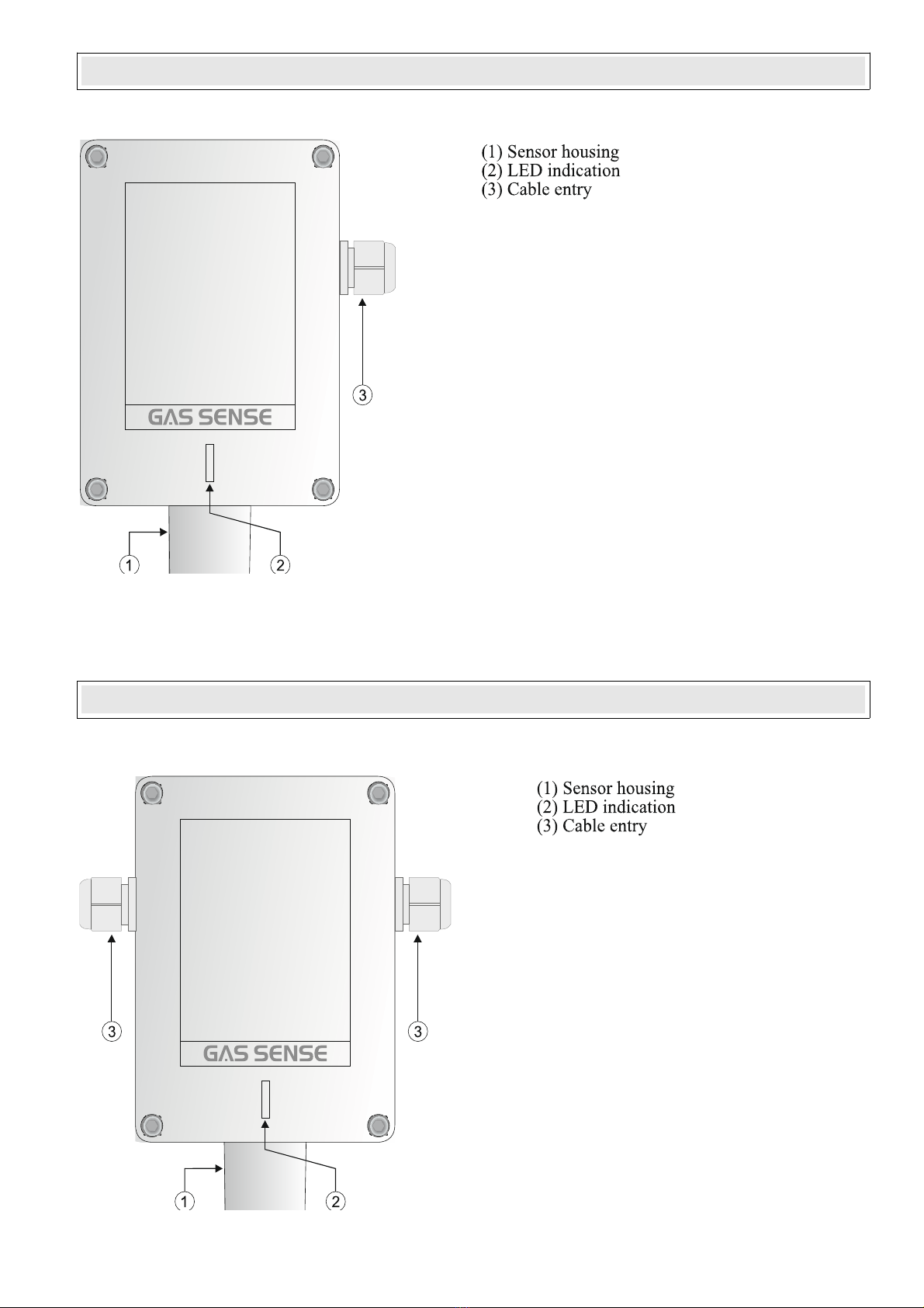
7.Front view....................................................................................................................................................
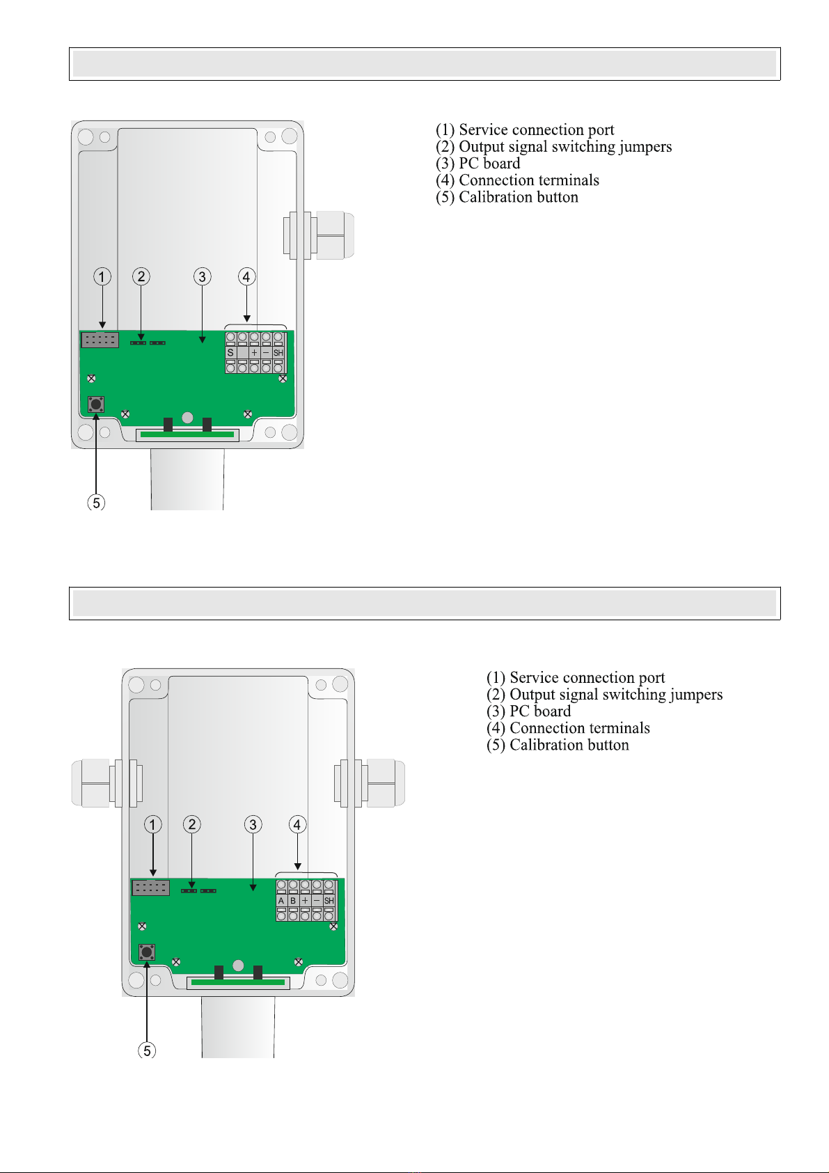
8.Inside view....................................................................................................................................................
9.Installation and wiring...............................................................................................................................
9.1.Mounting the sensor ..................................................................................................................................
9.2.Mechanical mounting ................................................................................................................................
9.3.Electrical connection .................................................................................................................................
9.4.Analogue gas detector GS-300.A ..............................................................................................................
9.5.Addressable gas detector GS-300. .........................................................................................................
10.Operating instructions .............................................................................................................................
10.1.Initial stabilisation ...................................................................................................................................
10.2.Working mode .........................................................................................................................................
10.3.Alarm 1 ...................................................................................................................................................
10.4.Alarm 2 ...................................................................................................................................................
10.5.Alarm 3 ...................................................................................................................................................
10.6.FAULT ....................................................................................................................................................
11.Sensor callibration ...................................................................................................................................
12.Maintenance and servicing......................................................................................................................
Cleaning ..........................................................................................................................................................
Servicing .........................................................................................................................................................
Servicing frequency ........................................................................................................................................
13.Ordering codes .........................................................................................................................................
14.Declaration of Conformity.......................................................................................................................

General Information
This manual is designed to provide users with simple and precise information. Manufacturer shall not be
held responsible or liable for any misinterpretation that may result from the reading of this manual.
Although every effort is made to ensure accuracy, this manual may contain unintentional technical
inaccuracies.
Please read the following notice carefully before installation and start-up, paying particular attention to
the end - user safety instructions. This user’s guide should be distributed to every individual involved in
the start-up, use, maintenance or repair of the product. The information contained in this manual, the data
and technical drawings are correct as of the date of publication. For additional information, please
contact Invest Electronics Ltd.
Manufacturer reserves the right to modify the technical characteristics of its equipment without notice to
improve product performance. This user manual and its contents are the inalienable property of Invest
Electronics Ltd
Safety Warnings
Installation and electric connections should be performed by a qualified professional, according to
Manufacturer's specifications and to the standards of authorities in the field. Failure to observe these rules
may result in serious injury. Accuracy, particularly regarding electricity and assembly (couplings, network
connections) is imperative.
Icons have been placed on the sensor to call attention to general use safety precautions. These labels are
an integral component of the sensor. The meanings of these labels are described below.
Symbols
Please refer to the instructions.
Caution: In the current operating mode, failure to adhere to the instructions preceding this symbol can
result in a risk of electric shock or death.
T is equipment must be grounded

Safety grounding terminal. A cable of adequate diameter must ground any terminal with this signal.
The accordance with Directive DEEE (2002/96/EC) this product may not be disposed with household
waste. Dispose of this product at a collection site intended for electrical waste.
Important Information
Gas detectors must be checked for correct functioning by a qualified person after the installation but
before putting into operation. The detector was checked for correct functioning prior to delivery. The
calibration was performed with suitable calibration gases. This does not release the user from the
obligation to perform a check with test gas when the transmitter is put into operation after the installation
and before putting into operation.
Limitation of liability
either Invest Electronics Ltd nor any other affiliated organization shall be held liable under any
circumstances for any damage whatsoever including, without limitations, damages for loss of production,
interruption of production, loss of information, controller failure, personal injury, loss of time, money, or
materials, or for any indirect or consecutive consequence of loss occurring during the use of the product
or the inability to use the product, even in the event that Invest Electronics Ltd had been informed of such
damages.
Warranty
We hereby guarantee that gas detectors GS-300.A/GS-300. have been manufactured and tested to the
highest quality standards.
We warrant above products to be free from materials and work defects for the period of 24 months from
the date of purchase. If such defects appears during the warrantee period products will be repaired or
replaced with new products without charge.

Tec nical specifications
General describtion:
A stationary gas detection system consists of a detector (transmitter) and a central controller. The detector
and the controller are connected with a cable. The detector converts gas concentration into an electric
measurement signal and transmits it via the cable for processing to the controller.
Gas detectors GS-300.A/GS-300. are intended for detection of explosive and toxic gases. They are
suitable for detection of different gases depending on gas detection element.
Measuring met od:
The following mesuring methods are used:
1.Cathalityc sensors for mesurement of explosive gases.
2.Electrochemical sensors for toxic gases.
3.Infrared sensors for CO2.
4.Semiconductor sensors for refrigerant gases.
Tabl.1
DETECTED GASES See Tabl. Ordering codes
Gas feed Diffusion
POWER SUPPLY
Working voltage 12 – 30 VDC
Power consumption 3W
OUTPUT SIGNAL
GS-300.A 4-20mA
GS-300. RS485
ENVIRONMENTAL CONDITIONS
Working temperature -20 - +50oC
Humidity range 10 – 90 % R.H.
Atmospheric pressure range 800 – 1100 hPa
MECHANICAL
Dimensions 159 x 120(150) x 50 mm
Weight 0,320kg
Enclosure material ABS
Ingress protection IP65
Cable connection Cable gland(s) M16 (M20)
CERTIFICATION
Conformity mark CE
Applied standards E 50270

Front view – gas detector GS-300.A
Front view – gas detector GS-300.N

Inside view – gas detector GS-300.A
Inside view – gas detector GS-300.N

Installation and wiring
Mounting t e detector
Gas detector for monitoring of flammable gases and leakages of toxic gases should be installed close to
potential sources of release. For gases heavier than air below and for gases lighter than air above the
source of release. Detaectors for monitoring at working places are installed at face / respiration level.
When deciding on the position for the transmitter, make sure that it is always accessible for service
and maintenance.
Mec anical mounting
Gas detector is attached to the wall via 4 mounting screws. Sensor opening to be placed downwards. Drill
4 holes according to the Drilling diagramme.
Drilling diagramme:
Electrical connections
The electrical connection must be carried out by a specialist and (with the controller) with the power
supply disconnected.
Analogue gas detector GS-300.A
Use shielded cable 3 x 1.5 mm2. The cross section of the cable depends on the cable length. For short
distances up to 200 m it may be sufficient to use 0.75 mm2 instead of 1.5 mm2. For longer distances the
cross section must be 1.5 mm2. The cable length must not be more than 1000 m.

CONNECTION DIAGRAME GS-300.A- ANALOGUE GAS DETECTOR 4-20mA
Addressable gas detector GS-300.N
The addresable gas detector GS-300. has 2 cable glands – for input and for output cable.
Gas detectors must be connected using shielded cable with twisted pair for communication A and B
terminals and another pair for the power supply of gas detectors.
The end of line resistor must be connected in the last device by placing of a end of line jumper.
Cable shielding must be connected to the cable shielding terminal of the gas controller.
CONNECTION DIAGRAME GS-300.N - ADDRESSABLE GAS DETECTOR RS485

Operating instructions
The gas detector GS-300.A/GS-300. has the following operation modes:
1.Initial stabilisation
Preheating and initial testing of gas sensing element.
Indication: Green LED is flashing quickly.
2.Working mode
In this mode sensor is ready to detect gas concentration.
Indication: Green LED is flashing slowly.
3.Alarm 1
First alarm level is reached.
Indication: Red LED is flashing slowly.
4.Alarm 2
Second alarm level is reached.
Indication: Red LED is flashing quickly.
5.Alarm 3
Third alarm level is reached.
Indication: Red LED lights permanently.
6.FAULT
Sensor element fault.
Indication: Orange LED is flashing.
Sensor calibration
Gas detectors must to be calibrated and periodically checked to ensure detector accuracy and system
integrity. It is important to install stationary gas detectors at locations where the calibration can be
performed easily. The intervals between calibration can be different from sensor to sensor. However, it is
good general practice to check the detector during the first 30 days after installation. During this period, it
is possible to observe how well the detector is adapting to its new environment. If the detector functions
properly for 30 continuous days, this provides a good degree of confidence about the installation. Any
possible problems can be identified and corrected during this time. Experience indicates that a detector
surviving 30 days after the initial installation will have a good chance of performing its function for the
duration expected. Most problems such as an inappropriate detector location, interference from other
gases, or the loss of sensitivity will arise during this time. Afterward, a maintenance schedule, including
calibration intervals, should be established.
ormally, a 6-monthly calibration period is adequate to ensure the effectiveness and sensibility of each
sensor. This check will also afford you the opportunity to maintain the system’s accuracy.
CALIBRATION PROCEDURE
Calibration of the gas detector includes two steps. First the “zero” must be set and then the “span” must
be calibrated.
1.To initiate calibration pres and hold the tactile button on the PCB or place the magnetic gas calibration
cup.
2.After 5sec all LED’s will flash.

3.After 2 more sec yellow LED will turn OFF, red LED is O and green LED is flashing once every
second for the period of 30seconds. In this case you may chose from the following:
-To calibrate the sensor - continue holding the button and apply zero gas;
-To refuse calibration on ZERO air - release the button (remove the magnetic cap) - red LED will flash for
2 sec.
4.Green LED and red LED start to flash alternately. ow you must apply the span gas and again pres and
hold the button or place the magnetic gas calibration cup. ow the alarm levels are automatically
adjusted. Red LED lights and green LED are flashing twice at every 2 seconds for 30 seconds. In this case
you may chose from the following:
-To calibrate the sensor - continue applying span gas for 30 seconds and red LED will flash for 2 seconds
confirming alarm levels setting;
-To refuse calibration of alarm levels - release the button or remove the magnetic cap and red LED will
flash for 2 seconds.
5.When you complete the above steps calibration is finished and all LED’s will flash for 5 seconds.
OTE: If during the calibration you release the button or remove the magnetic cap for more than 4
minutes calibration will be terminated and previously saved values for pure air and alarm levels will be
recovered.
Maintenance and servicing
Cleaning
If necessary, clean the exterior of the enclosure with a damp cloth. Do not use alcohol or ammonia based
liquids to clean the detector.
Servicing
We recommend the user to periodically inspect the proper triggering of alarm and fault relays, the buzzer
and indications on the front panel of the controller. Test must be done by applying etalone gas mixture to
the gas detectors.
The adjustment operations of the gas detection system must be done only by authorized, trained personnel
because they may compromise gas detection detection system reliability.
Servicing frequency
Invest Electronics recommends regular testing of fixed gas detection installations. The type of test
consists of injecting a standard gas mixture of sufficient concentration into the detector to set off the
preadjusted alarms. This test does not, replace a full calibration of the detector. Frequency of gas testing
depends on the industrial application in which the detectors are used. Inspection should be done
frequently during the first months after installation startsup, later it may be spaced out if no problem is
observed.
If a detector does not react upon contact with gas, it must be calibrated. The frequency of calibration will
depend on tests (humidity, temperature, dust, etc.); calibration should occur at least once every year. We
also recommend calibrating the detector after exposure to high gas concentrations. The site manager is
responsible for implementing the safety procedures on his site. Invest Electronics is not responsible for
implementing safety procedures.

Ordering codes
Analogue gas detectors GS- 300.A for combustible gases
Model – ordering code Detected gas Gas concentration
GS-300.A.MET.100 METHA E 0 - 100% LEL
GS-300.A.LPG.100 LPG 0 - 100% LEL
Analogue gas detectors GS- 300.A for toxic gases
Model – ordering code Detected gas Gas concentration
GS-300.A.CO.500 Carbon monoxide 0 - 500 ppm
GS-300.A. O2.30 itrogen dioxide 0 - 30 ppm
GS-300.A.H2S.100 Hydrogen sulphide 0 - 100 ppm
GS-300.A.AMM.100P Ammonia 0 - 100 ppm
GS-300.A.CL2.10 Chlorine 0 - 10 ppm
GS-300.A.O2.25 Oxygen 0 - 25%v
Analogue gas detectors GS- 300.A for refrigerant gases
Model – ordering code Detected gas Gas concentration
GS-300.A.AMM.2000 Ammonia 0 - 2000 ppm
GS-300.A.134A.2000 R-134a 0 - 2000 ppm
GS-300.A.404A.2000 R-404a 0 - 2000 ppm
GS-300.A.407C.2000 R-407c 0 - 2000 ppm
GS-300.A.410A.2000 R-410a 0 - 2000 ppm
GS-300.A.290.2000 R-290 0 - 2000 ppm
Addressable gas detectors GS- 300.N for combustible gases
Model – ordering code Detected gas Gas concentration
GS-300. .MET.100 METHA E 0 - 100% LEL
GS-300. .LPG.100 LPG 0 - 100% LEL
Addressable gas sensors GS- 300.N for toxic gases
Model – ordering code Detected gas Gas concentration
GS-300. .CO.500 Carbon monoxide 0 - 500 ppm
GS-300. . O2.30 itrogen dioxide 0 - 30 ppm
GS-300. .H2S.100 Hydrogen sulphide 0 - 100 ppm
GS-300. .AMM.100P Ammonia 0 - 100 ppm
GS-300. .CL2.10 Chlorine 0 - 10 ppm
GS-300. .02.25 Oxygen 0 - 25%v

Addressable gas sensors GS- 300.N for refrigerant gases
Model – ordering code Detected gas Gas concentration
GS-300. .AMM.2000 Ammonia 0 - 2000 ppm
GS-300. .134A.2000 R-134a 0 - 2000 ppm
GS-300. .404A.2000 R-404a 0 - 2000 ppm
GS-300. .407C.2000 R-407c 0 - 2000 ppm
GS-300. .410A.2000 R-410a 0 - 2000 ppm
GS-300. .290.2000 R-290 0 - 2000 ppm
This manual suits for next models
1
Table of contents
Other Gas Sense Gas Detector manuals