Absco Industries Assembly Instruction Manual
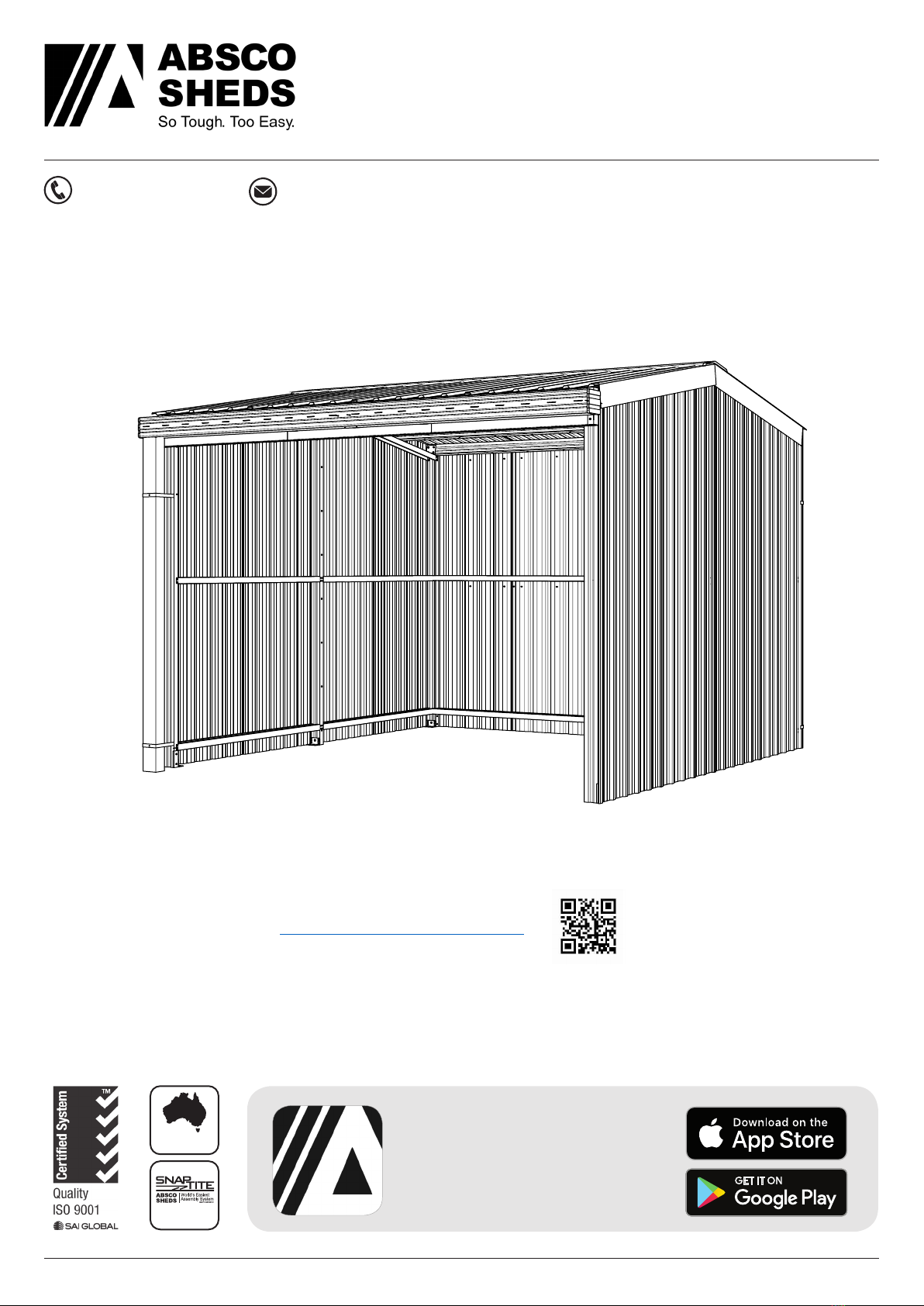
ABSCO RURAL SHED
MODEL: 3030RS-PTX
9’ 9 5/16” W x 9’ 9 5/16” D x 8’ 7/16” H
Model: 3030RS-PTX 19/07/2019 1.10 6
Guide for Connecting Frame Sections
Absco sheds’ frame assemblies are supplied with
10-16x16 self drilling wafer head phillips drive tek
screws
The wafer head minimises distortion to the sheet
cladding once it is fitted to the frame
Ensure that driver bits used to fasten these screws
is phillips drive, as similar alternatives (EG. Pozi
drive) increases the risk of stripping the head of
these screws.
Some holes are pre-punched in Absco sheds’ frame
sections, however the wide range of positions that
most fasteners are required for means that the
remainder have to be drilled as per the connection
being made
A 3mm drill bit is supplied for pre-drilling holes
where self drilling screws may be more difficult to
establish holes with (EG. Fitment of purlin brackets).
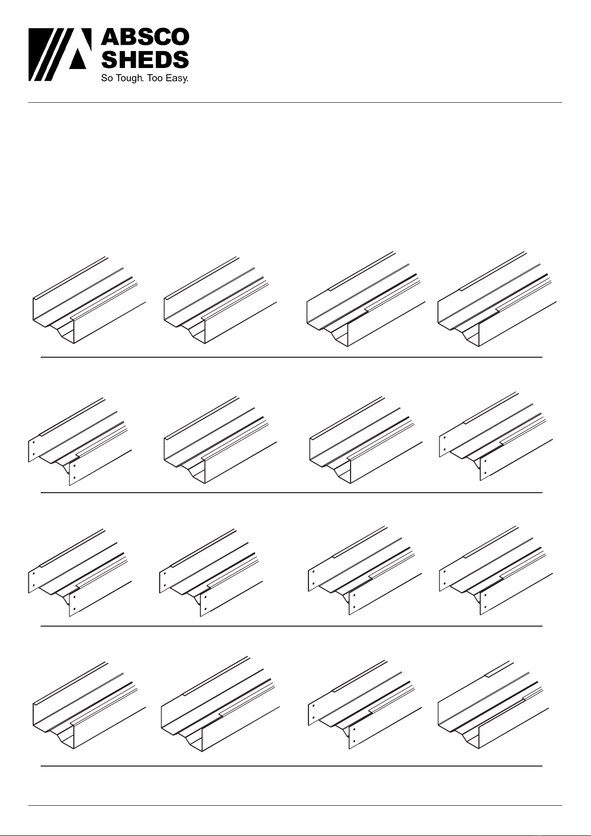
Absco sheds’ frame sections are manufactured
from light gauge steel, enabling for the notched
ends or lengths of one frame section to be spread
over the sides of another frame section, boxed
frame section or H-section.
Absco sheds’ frame sections are designed to nest
into one another to create boxed frame sections
Boxed frame sections are only required in some
parts of the entire frame assembly
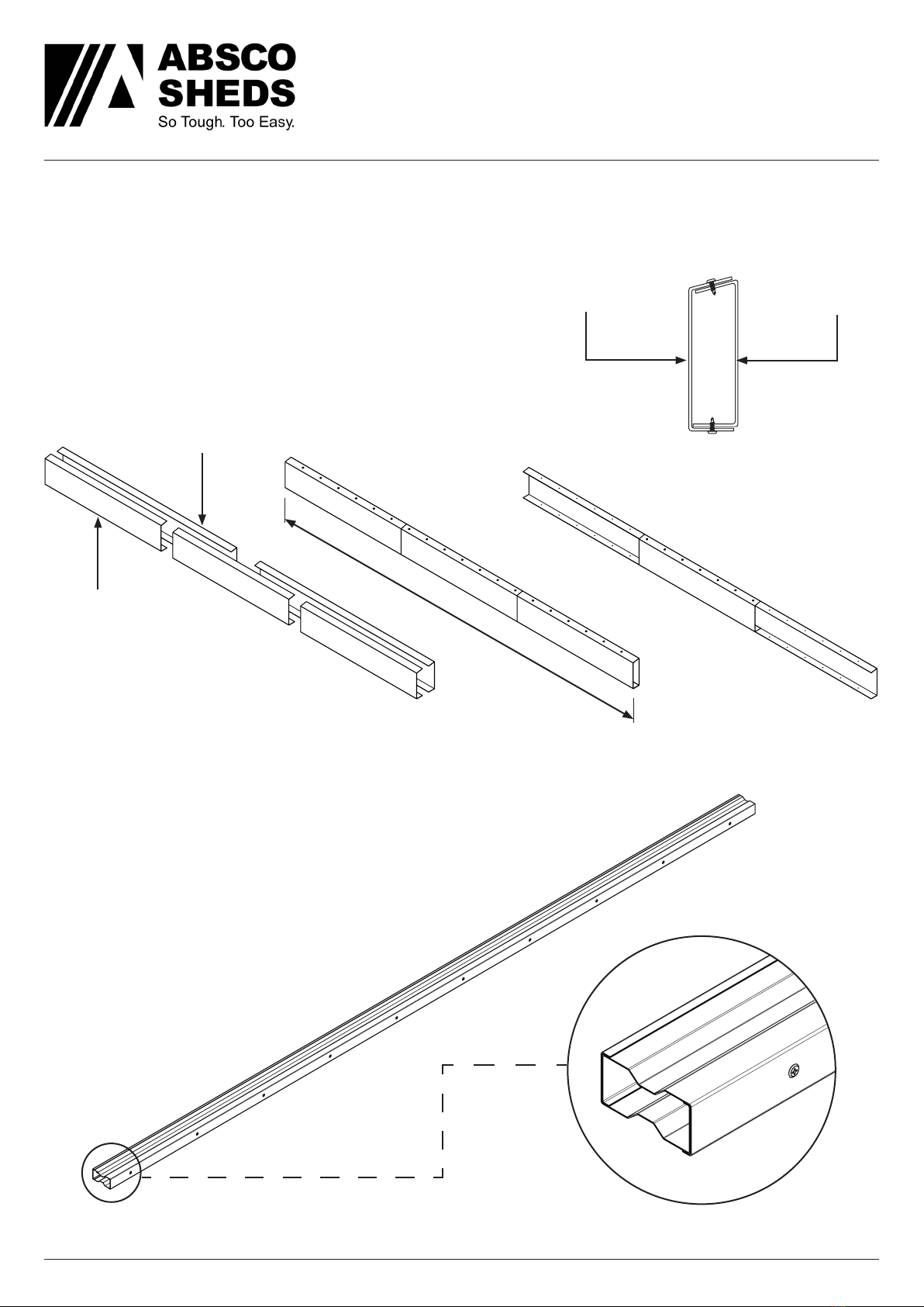
Boxed frame sections are fastened together using
the FAST014 tek screws supplied at 11 13/16”
centres along the length of each boxed frame
section
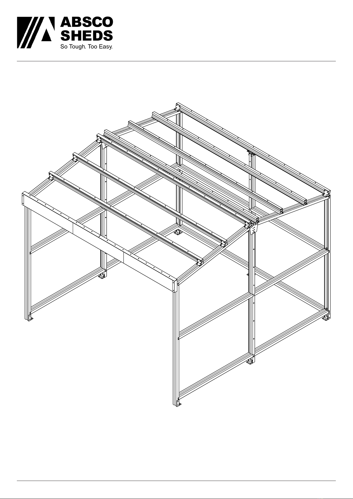
Some connections are designed to fasten more than two parts together. Connections may also not
feature a defined alignment or physical stop.
For these reasons, focus on arranging all parts of a frame assembly or subassembly together (to
the overall sizes and check measurements nominated) using minimal screws. This allows for easier
adjustment to various connections which may be necessary to achieve the overall dimensions and
check measurements that are nominated.
Fit the remaining screws once the frame assembly or subassembly is assembled as per the overall
dimensions and check measurements that are nominated
Boxing Frame Sections
A B
HIGH SIDE A
HIGH SIDE B
LOW SIDE B
LOW SIDE A FAST014
FAST014
HIGH SIDE
HIGH SIDE
(PRINT)
(PRINT)
LOW SIDE
LOW SIDE