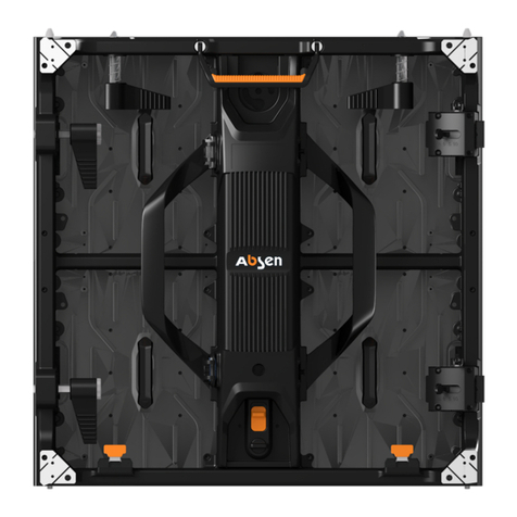
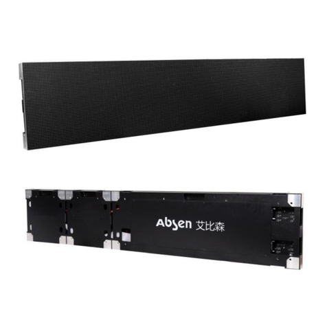
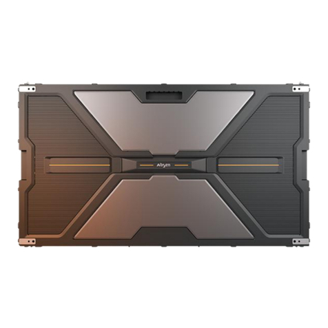
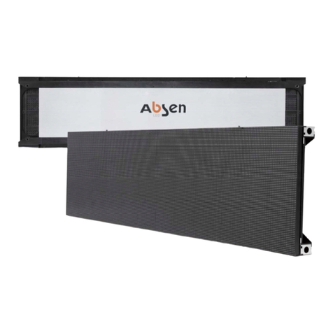
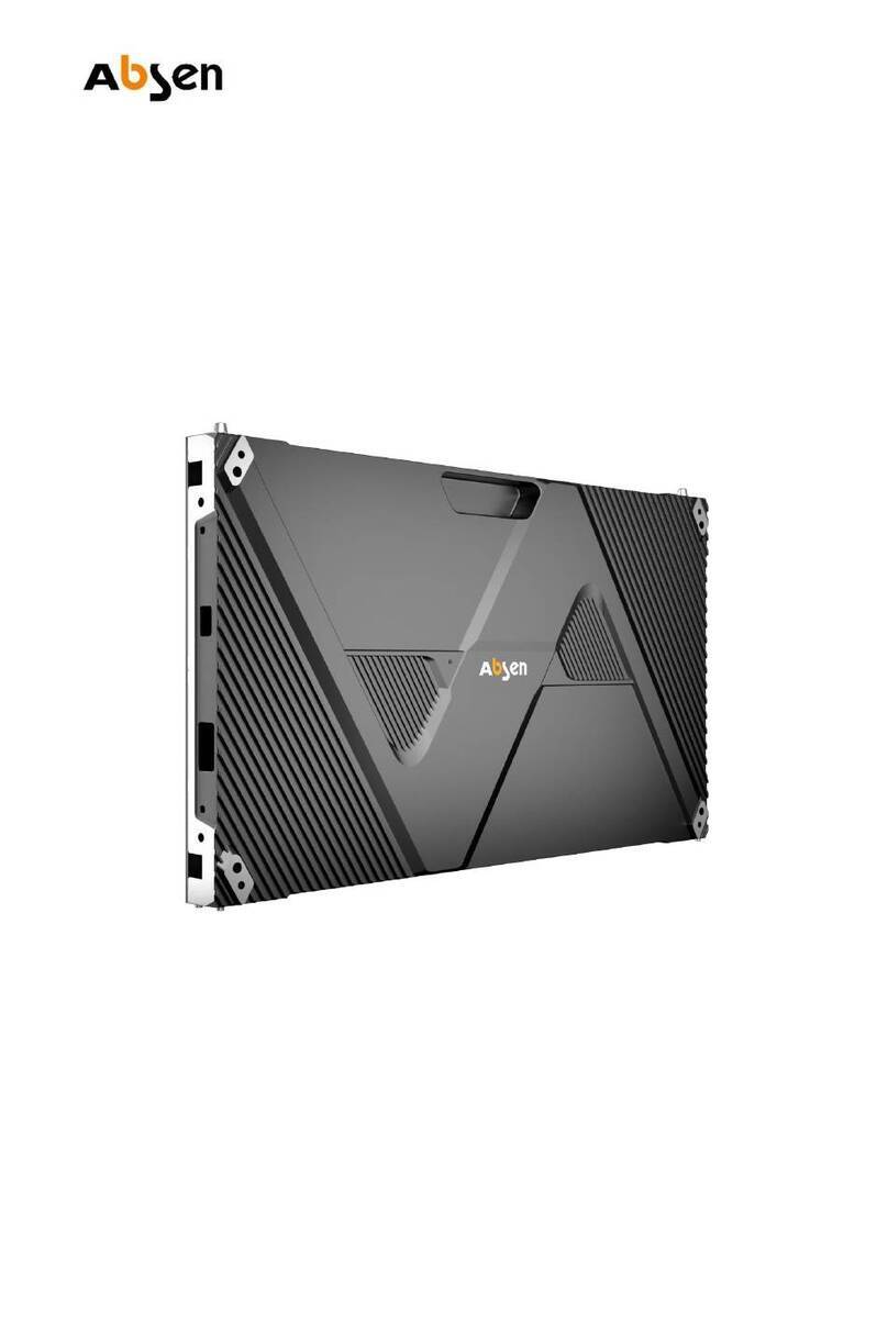
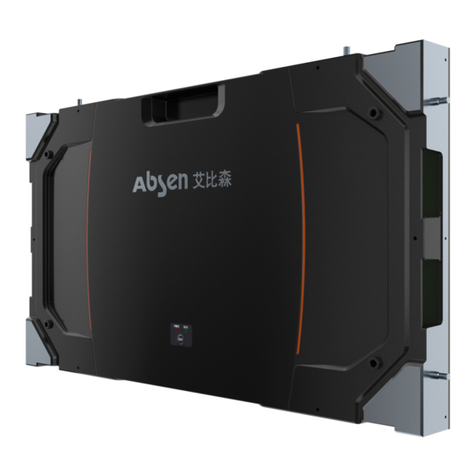
Absen HC Series User manual

New HC Series User Manual
Shenzhen Absen Optoelectronic Co.,Ltd.

- 2 - New HC Series User Manual
Catalogue
1. Product Introduction......................................................................................................................- 6 -
1.1Product Key Feature .................................................................................................................- 6 -
1.2 Product Specifications .............................................................................................................- 8 -
1.3Cabinet dimension figure ..........................................................................................................- 9 -
1.4Module dimension figure...........................................................................................................- 9 -
2. Product Components..................................................................................................................- 10 -
2.1 Cabinet Introduction...............................................................................................................- 10 -
2.2 Product Component Drawing.................................................................................................- 10 -
2.2.1 Mounting frame: used for wall mounting, including single and double frames .............- 10 -
2.2.2 Connector plates and bolts are used for installations with steel structure....................- 10 -
2.2.3 Flatness adjusting screw .............................................................................................- 11 -
2.2.4 Wire .............................................................................................................................- 11 -
2.2.5 Standard packaging:....................................................................................................- 11 -
3. Product Installation .....................................................................................................................- 12 -
3.1 Mounting Frame Installation...................................................................................................- 12 -
3.2 Connecting Plate Installation .................................................................................................- 13 -
3.3 Flatness adjustment mechanism ...........................................................................................- 15 -
3.3.1 Three-axis and six-way adjustment(Cabinet)...............................................................- 15 -
3.3.2 Three-axis and six-way adjustment(Module) ...............................................................- 16 -
4. Product Cabling ..........................................................................................................................- 17 -
4.1 Power Supply Wiring..............................................................................................................- 17 -
4.2 Signal Cable Wiring ...............................................................................................................- 18 -
4.3 Schematic diagram of system connection topology ...............................................................- 19 -
4.4 Power-on test.........................................................................................................................- 20 -
5. Maintenance ...............................................................................................................................- 20 -
5.1 Preparation Tools...................................................................................................................- 20 -
5.2 Maintenance Instructions .......................................................................................................- 20 -
5.2.1 Module Maintenance ...................................................................................................- 20 -
5.2.2 HUB board/Receiving card/Power supply maintenance ..............................................- 21 -
6. Common faults and troubleshooting ...........................................................................................- 23 -
New HC Series User Manual - 3 -
Safety Information
The following marks on the product and in this manual indicate important safety measures.
WARNING: Be sure to understand and follow all safety guidelines, safety instructions,
warnings and precautions listed in this manual. This product is for professional use only!
This product may result in serious injury or death due to fire hazard, electric shock, and
crushing hazard.
Please read this manual carefully before installing, powering up, operating and
maintenance of this product. Follow safety instructions in this manual and on the product.
If you have any questions, please seek help from Absen.
Beware of Electric Shock!
•To prevent electric shock the device must be properly grounded during installation. Do
not ignore using the grounding plug, or else there is a risk of electric shock.
•During a lightning storm, please disconnect the device’s power supply, or provide other
suitable lightning protection. If the equipment is not in use for a long time, please unplug
the power cord.
•When performing any installation or maintenance work (e.g. removing the fuses, etc.,)
make sure to turn off the master switch.
•Disconnect AC power when the product is not in use, or before disassembling, or
installing the product.
•The AC power used in this product must comply with local building and electrical codes,
and should be equipped with overload and ground fault protection.
•The main power switch should be installed at a location near the product and should be
clearly visible and easily reached. This way in case of any failure the power can be promptly
disconnected.
•Before using this product check all electrical distribution equipment, cables and all
connected devices, and make sure all meet current requirements.
•Use appropriate power cords. Please select the appropriate power cord according to the
required power and current capacity, and ensure the power cord is not damaged, aged or

- 4 - New HC Series User Manual
wet. If any overheating occurs, replace power cord immediately.
•For any other questions, please consult a professional.
Beware of Fire!
•Use a circuit breaker or fuse protection to avoid fire caused by power supply cables
overloading.
•Maintain good ventilation around the display screen, controller, power supply and other
devices, and keep a minimum 0.1 meter gap with other objects.
•Do not stick or hang anything on the screen.
•Do not modify the product, do not add or remove parts.
•Do not use the product in case ambient temperature is over 55 ℃.
Beware of Injury!
•Warning: Wear a helmet to avoid injury.
•Ensure any structures used to support, fix and connect the equipment can withstand at
least 10 times the weight of all the equipment.
•When stacking products, please hold products firmly to prevent tipping or falling.
•Ensure all components and steel frames are securely installed.
•When installing, repairing, or moving the product, ensure the working area is free of
obstacles, and ensure the working platform is securely and stably fixed.
•In the absence of proper eye protection, please do not look directly at the lit screen from
within a 1 meter distance.
•Do not use any optical devices that have converging functions to look at the screen to
avoid burning the eyes.
WARNING: Beware of suspended loads.
LED lamps used in the module are sensitive and can be damaged by ESD (electrostatic
discharge). To prevent damage to LED lamps, do not touch when the device is running or
switched off.
WARNING: manufacturer shall not bear any responsibility for any incorrect, inappropriate,
irresponsible or unsafe system installation.
Product Disposal
•Any component that has a recycling bin label can be recycled.
•For more information on collecting, reusing and recycling, please contact the local or
regional waste management unit.
•Please contact us directly for detailed environmental performance information.

New HC Series User Manual - 5 -
WARNING: Changes or modifications to this unit not expressly approved by the party responsible for
compliance could void the user’s authority to operate the equipment.
NOTE: This equipment has been tested and found to comply with the limits for a ClassB digital device,
pursuant to part 15 of the FCC Rules. These limits are designed to provide reasonable protection
against harmful interference in a residential installation.
This equipment generates, uses and can radiate radio frequency energy and, if not installed and used
in accordance with the instructions, may cause harmful interference to radio communications.
However, there is no guarantee that interference will not occur in a particular installation. If this
equipment does cause harmful interference to radio or television reception, which can be determined
by turning the equipment off and on, the user is encouraged to try to correct the interference by one
or more of the following measures:
—Reorient or relocate the receiving antenna.
—Increase the separation between the equipment and receiver.
—Connect the equipment into an outlet on a circuit different from that to which the receiver is
connected.
—Consult the dealer or an experienced radio/TV technician for help.

- 6 - New HC Series User Manual
1. Product Introduction
The new HC series products are high-definition and small pitch LED display screens specially
developed for control room. The size of the cabinet is 600x337.5mm, it is designed in a ratio of
27-inch 16:9, and the main pixel pitches are P1.5,P1.2,P0.9,P0.7, which can better display the
image details.
The products are primarily used in the field of professional control rooms, meeting room, high-
end business display.
1.1 Product Key Feature
The new HC series has 5 products: HC0.7 Pro Ⅱ,HC0.9 Pro Ⅱ,HC1.2 Pro Ⅱ,HC1.2 Ⅱ,HC1.5
Ⅱ, of which HC1.2 Ⅱ,HC1.5 Ⅱadopt the traditional 3-in-1 SMD surface patch technology
and common anode design, and HC0.7 Pro Ⅱ,HC0.9 Pro Ⅱ,HC1.2 Pro Ⅱadopt the 4in1
integrated encapsulation and HBB energy-saving technology design.
Advantages of 4 in 1 integrated encapsulation:
1. Better air tightness, which can improve the moisture resistance of products;
2. 4in1 pixel integration technology reduces solder points by 50%, and the stability of
product is better;
3. The adhesive force of the lamp is enhanced, the anti-collision capability is improved by
about 2.5 times, and the Probability of knocking off the lamp is greatly reduced;
4. Compared with SMD, 4 in 1 can make the flatness effect of the product better.
HC0.7 Pro Ⅱ,HC0.9 Pro Ⅱand HC1.2 Pro Ⅱadopt HBB energy-saving technology, which
can control the voltage of the drive chip more accurately, reduce the power consumption
of the product by 20%, and enhance the heat dissipation performance and high contrast
ratio.
The cabinet is integrally formed by die casting and made of aluminum alloy, which has the
characteristics of high precision, good flatness, difficult deformation, good heat dissipation,
etc.
The cabinet adopts honeycomb design,, and have hidden wire cover design. The whole is
beautiful and the integration effect is excellent after splicing.
The cabinet is designed in a ratio of 27 inches 16:9, and can be seamlessly spliced into
FHD/4K/8K display screen. FHD adopts HC1.5 Ⅱcabinet arrangement 5x5(135

New HC Series User Manual - 7 -
inches),HC1.2 Ⅱ/HC1.2 Pro Ⅱcabinet arrangement 4x4(108 inches) and HC0.9 Pro Ⅱ
cabinet arrangement 3 x 3 (81 inches).
Floating connectors are used between the module and the HUB, which can realize fine
adjustment of the splicing gap after assembly to ensure no bright and dark lines.
The magnetic attraction module is wirelessly connected, and the module can be assembled
and disassembled without screwing or detaching wires, thus being quick and convenient.
New HC series supports backup of dual power supplies and dual receiving cards. MTBF ≥
5000H, meeting the requirement of 7*24 hours. The product has strong anti-interference
capability, high reliability and stability, low radiation, safety and stability.
The product satisfies IEC TR62778-2014 Blue Light Hazard and EN62471:2008
Photobiological Safety Test, does not damage eyes and is not fatigued after long-term
viewing.
The cabinet and power supply have no fan design, and the quiet technology of < 25db
creates a comfortable working environment.
New HC series supports full front maintenance, module, power supply, receiving card and
HUB can be maintained from the front.
High gray scale, high refresh, high gray in the low light, high contrast, no ghosting and
caterpillar phenomenon, showing excellent display effect.
Support Absen new generation point-by-point correction technology (A5C+), with more
uniform and better picture. The module has its own correction data memory, and the
replacement module directly and automatically imports correction data.
Black Screen Automatic Energy Saving Technology: Black screen and some black screen
images automatically enter Energy Saving Mode for high efficiency and saving energy.
Support fixed installation mode,, quick and flexible installation.

- 8 - New HC Series User Manual
1.2 Product Specifications
Remark: Power consumption tolerance: ±15%, according to the actual situation.
Parameter
HC0.7 Pro Ⅱ
HC0.9 Pro Ⅱ
HC1.2 Pro Ⅱ
HC1.2 Ⅱ
HC1.5 Ⅱ
Physical
Parameter
LED Type
IMD 4in1
IMD 4in1
IMD 4in1
SMD1010
SMD1212
Pixel Pitch (mm)
0.78
0.93
1.25
1.25
1.56
Panel Dimensions
(WxHxD)/(mm)
600x337.5x50
Pixel Per Panel
768×432
640x360
480x270
480x270
384×216
Panel Weight (kg)
5.9
5.7
5.2
5.2
5.2
Panel Material
Al Die-Casting
Module Dimensions
(WxH)/(mm)
150 x 168.75
150 x 168.75
150 x337.5
150 x337.5
150 x337.5
Optoelectronic
Parameter
Brightness (nit)
600
Refresh Rate (Hz)
3840
2880
3840
3840
3840
gray scale(bit)
15
14
Contrast Ratio
4200:1
4500:1
5000:1
3000:1
3000:1
Color Temperature(K)
6500
Viewing Angle (H/V) (°)
160/120
160/125
160/120
160/120
160/140
Driving Type
1/32
1/60
1/46
1/45
1/48
AC Operating Voltage (V)
100~240
Power Consumption
(Max./Avg.)(W/m²)
340/115
680/225
510/170
520/175
420/140
Application
Parameter
Storage Temperature (℃)
-40~+60
-10~+40
Operating Temperature (℃)
-10~+40
Storage Humidity (RH)
10%~85%
Operating Humidity (RH)
10%~80%
IP Rating (Front/Rear)
IP40/IP21
Module Maintenance
Front
PSU & Others Maintenance
Front
Panel Installation Type
Fixed
Certificate
FCC,CE etc.

New HC Series User Manual - 9 -
1.3 Cabinet dimension figure
Unit: mm
1.4 Module dimension figure
Unit: mm
HC0.7 Pro Ⅱ/HC0.9 Pro ⅡHC1.2 Pro Ⅱ/HC1.2 Ⅱ/HC1.5 Ⅱ

- 10 - New HC Series User Manual
2. Product Components
2.1 Cabinet Introduction
Power port connection mode: The input end of the power cable is connected to the PWR IN interface, and
the output end is connected to the PWR OUT interface;
Signal port connection mode: Single card version, connect the signal line to DATA1 port; Dual card version
(backup) : DATA1 port is the main card signal cable port, and DATA2 port is the backup signal cable port.
2.2 Product Component Drawing
2.2.1 Mounting frame: used for wall mounting, including single and double frames
2.2.2 Connector plates and bolts are used for installations with steel structure.
1×1 Single frame
1×2 Double frame
Rear cover
(Power Port)
Anti-knock positioning mechanism
connection strap /rack hole
Cabinet connecting screw
Flatness adjustment hole
Handle
Rear cover
(Signal Port)
Test button/Indicator
钮/指示灯
Flatness adjustment hole
Screw

New HC Series User Manual - 11 -
2.2.3 Flatness adjusting screw
M6×10mm
2.2.4 Wire
Item
Figure
Connecting network cable
( upper and lower) 0.5m
Connecting network cable
( left and right) 0.8m
Connecting power wire
( upper and lower) 0.3m/0.5m
Connecting power wire
( left and right) 0.9m
Main power wire 10m
2.2.5 Standard packaging:
Carton packing, modules are assembled on cabinet and package together in carton
Package dimensions: 660×405×125 mm.
M6x30mm
M6x60mm
Cabinet connecting plate
Fixed connecting plate

- 12 - New HC Series User Manual
3. Product Installation
Installation type Supports mounting or steel structure.
3.1 Mounting Frame Installation
Step
Diagram
Step 1:
Use M6 tapping screws or M6
expansion screws to fix the
hanging plate on the flat wall.
Take the 1×2 double frame as an example
Step 2:
Install the screws in the
mounting holes on the back of
the cabinet.
Install 4 screws per cabinet.
Step 3:
Install the cabinet (without
module) on the frame: install it
layer by layer from bottom to
top.
Note: The left and right sides
and the upper and lower sides of
the cabinet are fixed with
locking screws.

New HC Series User Manual - 13 -
Step 4:
After all the cabinets assembled,
connect all the power and data
cables.
Step 5:
The installation module should
be installed according to the
corresponding number of the
module and the cabinet.
From the front view, module XX-
1 is installed on the leftmost side
of the cabinet, and module XX-4
is installed on the rightmost side
of the cabinet. (Note: "XX"
represents for cabinet number).
3.2 Connecting Plate Installation
Step
Diagram
Step 1:
Remove the cabinet from the
packaging and remove the
anti-knock screws that need to
be installed in the bottom row
of the whole screen. The anti-
knock screws are at the bottom
of the cabinet, 4 for each
cabinet.
XX-1 module
XX-4 module

- 14 - New HC Series User Manual
Step 2:
Using an M6×30mm socket hex
screw, pass through the front
mounting hole of the cabinet
from the front and lock into the
screw hole of the cabinet
connecting plate on the back.
Step 3:
The M6*60mm screws through
the cabinet connecting plate,
and connected with the fixed
connecting plate.
Step 4:
Install the second layer of
cabinet, and lock the screws
between the upper and lower
cabinet.
(Tighten the screws using the
soft sleeve tool)

New HC Series User Manual - 15 -
Step 5:
Lock the cabinet with
M6*30mm to the cabinet
connecting plate.
Step 6:
Repeat the preceding steps to
install the next cabinet.
3.3 Flatness adjustment mechanism
3.3.1 Three-axis and six-way adjustment(Cabinet)
When the stitching between the cabinets is not smooth and needs to be adjusted, the
position can be fine-tuned by the flatness adjustment screw. The positions of adjusting screws
are designed on the top (2 pcs), side (2 pcs) and back (4 pcs) of each cabinet (red circle in the
following picture). Use flatness adjustment screw and 3mm L-shaped hexagon adjustable
wrench to fine tune the cabinet position.
Vertical view
Back view

- 16 - New HC Series User Manual
3.3.2 Three-axis and six-way adjustment(Module)
When there is unflatness between the modules and needs to be adjusted, the magnet adjustment tool can
be used to adjust the height of the magnet on the cabinet to achieve the flatness of the Z axis, and slightly
move the modules by hand to achieve fine adjustment of the X/Y axis position.
X axis direction
adjustment
hole
Y axis direction adjustment hole
Z axis direction adjustment hole
Flatness adjusting screw
Local view
The floating connector between the module and the HUB
enables the module to be fine-tuned on the X/Y axis.
Z axis adjustment can be
realized by adjusting the
height of the magnet on the
cabinet with a special magnet
adjustment tool.

New HC Series User Manual - 17 -
4. Product Cabling
Preparation before cabling
Before applying power and signal source to the screen, please check power and data cables
connections carefully and make sure they are wired correctly. Use a multimeter to test the L, N
and PE lines in AC power input port and make sure the three lines are not short-circuited.
Power cable connection instructions: Please calculate and select the appropriate model of
distribution cabinet or socket according to the maximum power consumption. Please consult your
electrician or distribution cabinet manufacturer for specific selection scheme. The input voltage
of the cabinet is 100-240V/AC. The 3×1.5 mm2power cable is used from the distribution box to
the cabinet. Please confirm the input voltage, the number of cabinets loaded on each power cable
will be different upon different voltages and product models. (Please feel free to contact our
after-sales service department if you cannot confirm).
4.1 Power Supply Wiring
Taking a [4x4] HC1.2 Ⅱcabinet for example, data and power wiring schematics are shown
below:
The total power of 16 HC1.2 Ⅱcabinets is 16 x 0.6 x 0.3375 x 520W=1.7kW. First, connect the
cabinets in series with connecting power lines, and the 3×1.5 mm2power cable is used for
connecting from the cabinet of bottom layer to the distribution box or socket.
NOTE:WHEN THE INPUT VOLTAGE IS 220V, EACH 3×1.5 MM
2POWER CABLE CAN CARRY UP TO 16 CABINETS.WHEN THE INPUT
VOLTAGE IS 110V, EACH POWER CABLE CAN CARRY UP TO 8CABINETS.
Screen-connected power cable
Cabinet-connected power cable

- 18 - New HC Series User Manual
4.2 Signal Cable Wiring
The signal cable of standard version uses RJ45 CAT5 network cable(The HC0.7 Pro Ⅱuses CAT6A
network cable or above), and the network cable interface of the cabinet can be used for input and
output. For the "S" type of up down connection, please calculate the resolution according to the
pixels of each cabinet and connect the signal cables according to the loading range of the sending
card.
When the cabinet is single-card version, DATA1 is in use and DATA2 is vacant.
When the cabinet is dual-card version, If signal backup is required, DATA1 port is the signal
network port on the main card and DATA2 port is the signal network port on the backup card.
Note: The range of loaded pixels of each net port cannot exceed 655360 points(except HC0.7 Pro
Ⅱ).
Take the single power/single receiving card version as an example:
Model name
Standard cabinet size
power consumption
(Max)
Number of
cabinets with
load for power
cable (220V)
Number of
cabinets with
load for power
cable (110V)
HC0.7 Pro Ⅱ
600x337.5x50mm
340 W/㎡
26
13
HC0.9 Pro Ⅱ
680 W/㎡
13
6
HC1.2 Pro Ⅱ
510 W/㎡
17
8
HC1.2 Ⅱ
520 W/㎡
16
8
HC1.5 Ⅱ
420 W/㎡
20
10
Model name
Standard cabinet
size
Cabinet
resolution
Number of cabinets
with load for single
network cable
Remark
HC0.7 Pro Ⅱ
600x337.5x50mm
768×432
Cabinets≤6
A single network cable can
load 1080P resolution, and
16 network cables can
load the standard 8K
resolution.
HC0.9 Pro Ⅱ
640x360
Cabinets≤2
To calculate the maximum
number of cabinets carried
by a single network cable,
calculate the number of
cabinets in the rectangular
area carried by the
network cable
HC1.2 Pro Ⅱ
480x270
Cabinets≤5
HC1.2 Ⅱ
480x270
Cabinets≤5
HC1.5 Ⅱ
384x216
Cabinets≤7

New HC Series User Manual - 19 -
4.3 Schematic diagram of system connection
topology
This product cannot store or display video content solely on itself. To perform normal work , the
screen requires video source from the output device such as PC, laptop, media player, etc. and
Computer
Main signal cables
Main signal cable
Main signal cable
Main signal cable
Main signal cable
Main power cables
USB control cable
HDMI-DVI cable
Distribution
box

- 20 - New HC Series User Manual
one or more sending box to receive and feed the source to it.
4.4 Power-on test
After the cabinet connection is completed, please use a multimeter to measure whether there is
short circuit at the AC input (L/N/PE) and DC output (VCC/GND) of the power supply. If a short
circuit is found, please check the circuit carefully. After ensuring the cable is normal, switch on the
power to electrify the cabinets to work.
Note: Please refer to the software user manual for software operation.
5. Maintenance
5.1 Preparation Tools
Preparation tools include: module front service tool, cross screwdriver, multimeter, etc.
Maintenance
Tool List
Tools type
function
Diagram
Module front
service tool
Installation and removal LED
module
PH2 cross
screwdriver
Installation and removal HUB,
receiving card, power supply
PH00 cross
screwdriver
Installation and removal the
AC fixing screws on the
power supply
multimeter
Measure power cables and
distribution boxes
5.2 Maintenance Instructions
5.2.1 Module Maintenance
Put the front service tool onto the surface of the module, then press the button of the tool to
suck out the module, hold the module by hand and release the button.
Take HC1.2 Pro Ⅱas an example(HC0.7 Pro Ⅱand HC0.9 Pro Ⅱare designed with small size
PCB, which requires the use of a dedicated small PCB module maintenance tool):
This manual suits for next models
5
Table of contents
Other Absen Monitor manuals

Absen
Absen K Series User manual

Absen
Absen JP Series User manual

Absen
Absen A27 Pro Series User manual

Absen
Absen CR Series User manual

Absen
Absen AX Series User manual

Absen
Absen X3 User manual

Absen
Absen A27 Plus Series User manual

Absen
Absen N4 User manual

Absen
Absen N Plus Series User manual

Absen
Absen K Plus Series User manual