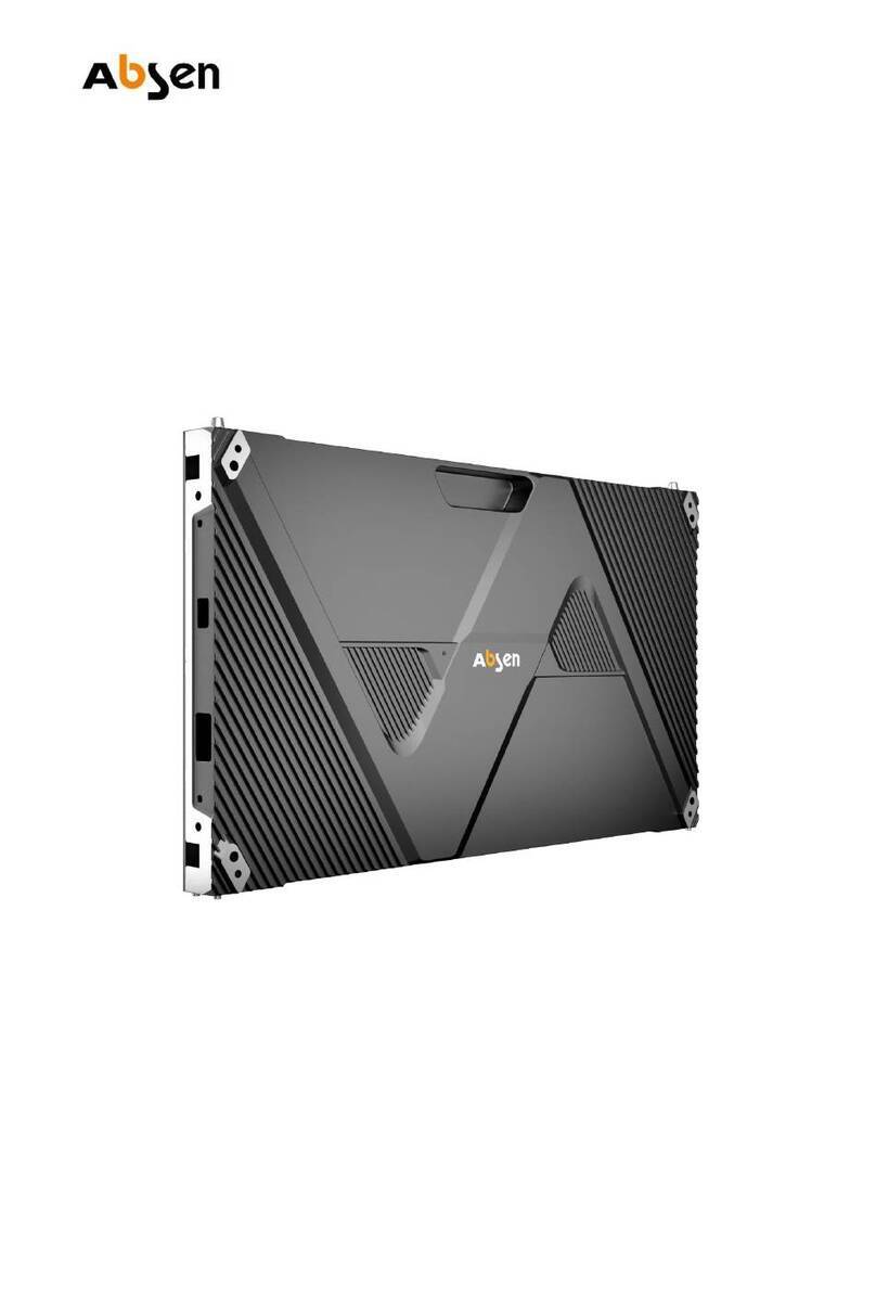
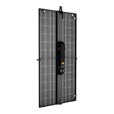
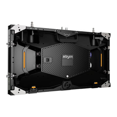
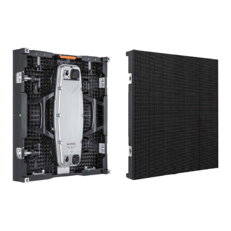
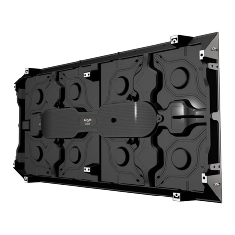
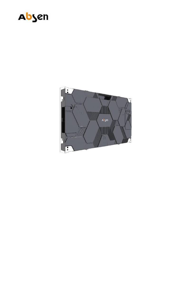
Absen N4 User manual

LeadingLEDApplications
User Manual
NSeries
Easy Maintenance Fast Installation
Slim &
Light Weight
Front & Rear
Servicing
High Grayscale Intelligent Monitor
N3/N4/N4W/N5

- 01 - N Series User Manual
Table of Contents
02-03
04
04
06
07
Safety Information
Product Introduction
About N Series
Product Specifications
05
Product Dimensions
Product Value Features
08
08-10
11
Product Components
Product Structure / Electronic Components Details
08
Cabinet Introduction
Product Installation
13-14
Front Installation Instructions (Wall-mounting)
15
16
16
17
17
18
Product Wiring
11
Front Installation / Rear Installation
Power Cable Wiring
Power Supply Wiring
Network Cable Wiring
15
12
13
Floor Installation
Wall-mounting Solution
12
Use Sub-frame for Fast Installation
Maintenance
Preparation Tools
Module Front & Rear Maintenance
18
Check for Power Supply Short Circuit
Leading LED Applications

N Series User Manual - 02 -
Safety Information
The following marks on the product and in this manual indicate important safety measures.
WARNING!
Safety Risk!
Might cause
equipment damage
Or safety risk.
WARNING!
Please read the
manual before
operating.
WARNING!
Dangerous Voltage!
Might cause
equipment damage
or electric shock.
WARNING!
Hot Surface!
Do not touch.
WARNING!
Flammable! WARNING!
Possible damage
to eyes.
WARNING!
Please read the Safety Measures listed in this section carefully before
installing, switching on, operating and maintenance of this product.
Beware of Electric Shock!
• To prevent electric shock the device must be properly grounded during installation. Do not ignore
using the grounding plug, or else there is a risk of electric shock.
• During a lightning storm, please disconnect the device’s power supply, or provide other suitable
lightning protection. If the equipment is not in use for a long time, please unplug the power cord.
• When performing any installation or maintenance work (e.g. removing the fuses, etc.,) make sure to
turn off the master switch.
• Disconnect AC power when the product is not in use, or before disassembling, or installing the
product.
• The AC power used in this product must comply with local building and electrical codes, and should
be equipped with overload and ground fault protection.
• The main power switch should be installed at a location near the product and should be clearly
visible and easily reached. This way in case of any failure the power can be promptly disconnected.
• Before using this product check all electrical distribution equipment, cables and all connected
devices, and make sure all meet current requirements.
• Use appropriate power cords. Please select the appropriate power cord according to the required
power and current capacity, and ensure the power cord is not damaged, aged or wet. If any
overheating occurs, replace power cord immediately.
• For any other questions, please consult a professional.
Leading LED Applications
WARNING: Be sure to understand and follow all safety guidelines, safety instructions, warnings and
precautions listed in this manual.
This product is for professionals use only!
This product may result in serious injury or death due to fire hazard, electric shock or on dropping.
Please read this manual carefully before installing, powering up, operating and maintenance of this
product.
Follow safety instructions in this manual and on the product. If you have any questions, please seek
help from Absen.

- 03 - N Series User Manual
Leading LED Applications
WARNING: Beware of suspended loads.
LED lamps used in the module are sensitive and can be damaged by ESD (electrostatic discharge).
To prevent damage to LED lamps, do not touch when the device is running or switched off.
WARNING: The manufacturer shall not bear any responsibility for any incorrect, inappropriate,
irresponsible or unsafe system installation.
Beware of Fire!
• Use a circuit breaker or fuse protection to avoid fire caused by power supply cables overloading.
• To avoid fire caused by power supply cables overloading, do not connect to the same power supply
point for more than 8 cabinets(N4W 6 cabinets)at a voltage of 100-120V, or 16 cabinets(N4W 12
cabinets)at a voltage of 200-240V.
• Maintain good ventilation around the display screen, controller, power supply and other devices, and
keep a minimum 0.1 meter gap with other objects.
• Do not stick or hang anything on the screen.
• Do not modify the product, do not add or remove parts.
• Do not use the product in case ambient temperature is over 40℃.
Beware of Injury!
• Warning: Wear a helmet to avoid injury.
• Ensure any structures used to support, fix and connect the equipment can withstand at least 10
times the weight of all the equipment.
• When stacking products, please hold products firmly to prevent tipping or falling.
• Ensure all components and steel frames are securely installed.
• When installing, repairing, or moving the product, ensure the working area is free of obstacles, and
ensure the working platform is securely and stably fixed.
• In the absence of proper eye protection, please do not look directly at the lit screen from within a 1
meter distance.
• Do not use any optical devices that have converging functions to look at the screen to avoid burning
the eyes.
Product Disposal
• Any component that has a recycling bin label can be recycled.
• For more information on collecting, reusing and recycling, please contact the local or regional waste
management unit.
• Please contact us directly for detailed environmental performance information.

- 04 -
Product Introduction
About N Series
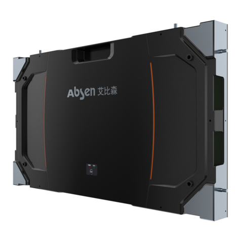
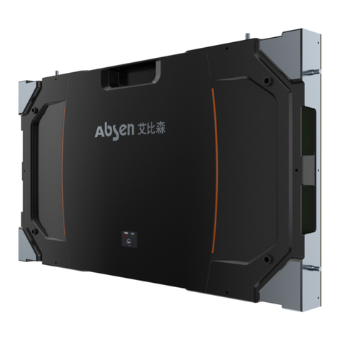
N3/N4/N4W/N5 are indoor fixed mounted high-definition display with unique competitive advantages. Designed in a long
rectangle shape with full aluminum structure, it looks like a tablet. Its cabinets are light and thin, only 8.8kg/cabinet(N4W
9.2kg), and only 54mm thickness. The thin cabinets are made of aluminum, use magnetic modules, support complete
front and rear installation and complete front and rear maintenance, and don’t require a maintenance channel.
The product is equipped with smart monitoring system, and uses a fan-less design for cabinet and power supply,
ensuring it is super-quiet, with exceptional heat dissipation. It features highly flat and smooth display plane, precision
cabinet and module assembly, and very strong structure. Standard Cabinet Dimension is: 1152X288X54mm.
The product is primarily used at hotel ballrooms, TV stations, commercial chain stores, branded snack stores, transpor-
tation hubs, supermarkets, banks, churches, airports, railway stations, theaters, company lobbies, high-end clubhouses,
museums, large conference rooms, and for various other applications.
Nowadays, with the LED display industry becoming severely standardized, N Series stands out among all similar
products with its delicate appearance, thin and light structure, excellent display effect, full-featured functions, easy
maintenance, smart monitoring and other unique advantages, providing good business opportunities for capable and
influential contractors, service providers and advertisers.
N Series User Manual
Leading LED Applications
Front
Rear

- 05 - N Series User Manual
Leading LED Applications
288mm
1152mm
Cabinet Dimension
Module Dimension
54mm
288mm
288mm
L E D
Product Dimensions

- 06 -
Product Specifications
Pixel Configuration
Physical
Parameters
Electronic
Parameters
Optical
Parameters
Electrical
Parameters
Environmental
Parameters
Product
Installation
Color Grayscale (Bit)
SMD 2121 SMD 2121 SMD 2121SMD 1921
3.2 4 4 5.14
360×90 288×72 288×72 224×56
288×288 288×288 288×288 288×288
Aluminum
16
65536
1920
1/15 1/12 1/12 1/7
50/60
1000 1000 4000 1000
7500 7500 7500 7500
160
140
2000:1 3000:1 3800:1 3000:1
100~240
50/60
-40~+60℃
450
150
450
150
540
180
450
150
Pixel Pitch (mm)
Grey Scale per Color (Level)
Refresh Rate (Hz)
Pixel Matrix per Cabinet
Drive Mode
Module Size (L×W)/ (mm)
Frame Frequency (Hz)
Cabinet Dimension (L×W×H) / (mm)
Cabinet Material
Color Temperature (K)
Brightness (cd/m
2
)
Horizontal Viewing Angle (°)
Vertical Viewing Angle (°)
Contrast Rate
AC Input Voltage (V)
AC Input Frequency (Hz)
Maximum AC Input Power (W/m
2
)
Average AC Input Power (W/m
2
)
Storage Temperature (℃)
Working Temperature (℃)
Storage Humidity (RH)
Working Humidity (RH)
IP Rating (Front/Rear)
Typical Life (hrs)
-10~+40℃
IP50/IP51
10%~90% non-condensing
100,000
Cabinet Installation Method Fixed Installation
1152×288×54
N Series User Manual
Leading LED Applications
Technical Specifications N3 N4 N4W N5
Cabinet Weight (kg) 8.8 8.8 9.2 8.8
UTP cable: <100 m; Single-mode fiber: <10 kmSignal Transmission Distance

- 07 - N Series User Manual
Leading LED Applications
Product Value Features
• Stylish and sophisticated appearance. Looks like a tablet, and the rectangular appearance makes it easy to change
dimensions.
• Light and thin product. Cabinet dimension 1152x288mm, weighs only 8.8kg/cabinet(N4W 9.2kg), with only 54mm
thickness, with more than 25% reduction in weight and over 35% reduction in thickness compared to similar products in
the market.
• Brand new smart monitoring. Monitoring card not required to monitor signal receiving cards, modules, cables, tempera-
ture, LED, etc. Abreakthrough from traditional architecture, reducing wiring and failure points.
• Supports PCs, tablets, mobile phones and other smart terminals to connect to the display for monitoring screen
operation.
• Smart Modules: Module can store ID number, production date, order information, usage duration, color coordinates,
current and other information. More convenient and practical.
• Complete front or rear maintenance. Perfect for environments where only rear maintenance is available like window
display, but also perfect for environments where only front maintenance is allowed, such as wall mounted installation at
malls.
• Complete front installation and maintenance can be adopted for wall-mounted installation, with magnetic modules,
power supply, signal receiving card, HUB, cable wirings, etc., accessible from the front, ensuring easy and fast
servicing, and zero maintenance channel requirement.
• Magnetic modules enable fast and convenient module installation and disassembly without screws.
• Cabinets can be installed both horizontally and vertically. The module can be rotated along with cabinets by 90 degrees
for assembly (rotating the module and cabinet together does not affect the viewing angle), ensuring the screen can be
installed vertically, to meet customers’ different installation requirements.
• Sub-frame enables faster installation.
• Fan-less design for cabinets and power supply, eliminating noise and reducing power consumption. More energy
savings.
• Uses crystal head sockets and reliable power plug sockets for signal and power cable connections between cabinets
and signal source, and power plug and socket, for faster and safer connections.
• Easy cabinet testing and operating status monitoring with external test button and indicators.
• High definition ensures excellent and super clear display effect. No ghost shadows or caterpillar problems, with high
grayscale, high refresh rate, and high grayscale at low brightness, highlighting exceptional display affect.
• Super large viewing angle, high contrast ratio: 160/140 no dark spots phenomenon. Uses TOP type SMD LED,
combined with light trap mask design, ensuring excellent optical effects.
• Supports Absen’s 3rd Generation Pixel-by-Pixel Correction (A3C) technology, ensuring even images. Different batches
produced within one year can be mixed and used together. Module is designed with built-in data correction memory, so
that users can directly replace modules without cumbersome setup, and can easily import and calibrate data.
- 08 -
NSeries User Manual
LeadingLED Applications
Product structure consists of two parts: Cabinet and module.
Product Components
Cabinet Introduction
Product Structure / Electronic Components Details
Cabinet structure: Full aluminum cabinet is extremely thin and light. Cabinet can be installed either horizon-
tally or vertically.
Mounting holes
Positioning Column
Power output
Test button
Indicator
Power input
Signal Input/Output
Horizontal Installation
Vertical Installation

- 09 - N Series User Manual
Leading LED Applications
Up and down signal cable, 0.3m length:
Left and right signal cable, 1.5m length:
Up and down power cable, 0.3m length:
Screen long power cable, 10m length:
Modular structure: Magnetic modules. Relative to the cabinet structure, modules can be rotated by 90
degrees for installation, so that the cabinet can be installed vertically or horizontally. When installed
vertically, the module needs to be rotated by 90 degrees, so as not to affect left and right viewing angle.
287.7mm
16.1mm
30.6mm
287.7mm
87°
N
L
E
N
L
E
L
N
L
N

- 10 -
Packaging
Installation-use connecting plates and mounting bolts
4-in-1 Carton Packing
100mm
74mm
4mm
100mm
70mm
Connecting Plates M8x60 Bolts
Wooden Case Packing
1218.0mm
324.0mm
N Series User Manual
Leading LED Applications

- 11 -
Module Module
Various installation methods are available for this product: front installation, rear installation, floor installa-
tion, using sub-frame for fast installation, as well as wall-mounted installation.
Remove the modules from left and right sides of the cabinet, use M6x60 bolt at the front mounting holes to
fix it to the steel structure. After it is fixed properly, connect power cord and signal lines, and then restore
the removed modules.
Use M8x60 bolts and connecting plates to fix onto the 40X40 square hollow bars.
Front Installation
Rear Installation
Product Installation
Remove modules
from both sides module
Connecting Plates M8X60 Bolt
M6X60 bolt fixed
on steel structure
Steel construction
40X40 square hollow bars
Front Installation Hole
N Series User Manual
Leading LED Applications

- 12 -
N Series User Manual
Leading LED Applications
Sub-frame
A floor support stand is required for floor installation, so that cabinets can be mounted onto the support
stand.
When installing, first fix 4 (2 to 4) cabinets onto the sub-frame, and then mount the sub-frame onto the steel
structure or wall, to achieve fast installation.
Note: Front or rear installation can also be used for sub-frame installation.
Floor Installation
Use Sub-frame for fast installation
Front installation hole
Rear installation hole

- 13 - N Series User Manual
Leading LED Applications
Sub-frame
Front installation hole
Sub-frame
Wall-mounting Solution
Front Installation Instructions (Wall-mounting)
Install cabinets onto the sub-frame or fixed structure, and then directly mount the sub-frame onto the wall,
to achieve wall-mounting installation.
Step 1:
Install cabinets onto the sub-frame and splice 2 to 4 cabinets. Number of cabinets is based on actual
requirements at installation site.
Wall Wall mounting device

Cabinet installation is completed with sub-frame
- 14 -
N Series User Manual
Leading LED Applications
M10 Expansion
screws
Wall
Step 2:
Take a properly spliced cabinet, remove modules
from four corners, mark installation positions on the
wall according to the mounting holes on the
sub-frame.
Step 3:
According to the installation positions marked on
the wall, install M10 expansion screws.
Sub-frame
Module
Installation
hole
Mark
Step 5:
After wiring is completed, insert modules back at
the four empty corners. Repeat the same proce-
dures to install the next spliced cabinet.
Step 4:
Install the cabinet: Mount cabinets onto the wall
corresponding to the M10 expansion screw positions,
and then lock M10 nut (flat cushion + spring washers)
M10 nut (flat cushion
+ spring washers)

- 15 -
• Preparation before wiring
Before connecting to power supply and switching on control signal to the entire screen, please carefully
check the power supply and signal cable connections. Please carefully check the "L" line, "N" line and "PE" of
each cabinet’s AC inlet, and ensure there is no short circuit between the three lines (Use multimeter to
measure).
• Power Supply Cabling Instructions
Please calculate and select the power distribution box or socket type based on 450 w/m2 (N4W 540w/m2)
maximum power consumption. Please consult your power distribution box manufacturer to specifically match.
Cabinet’s input voltage is 100-240V/AC, and 3X1.5mm2power cable is used to connect from distribution box
to cabinet. When input voltage is 220V, each power supply can be used to supply power for maximum 16
cabinets. When the input voltage is 110V, each power supply can be used to supply power for maximum 8
cabinets.
• Cabinet terminal connection diagram
Take 2x4 cabinets for example; following are the instructions for power and signal cable connection method:
Product Wiring
Power Supply Wiring
Indicators: Green is signal indicator,
Red is power indicator Cabinet self-test button
Signal interfaces,
no difference for input and output
Power female plug,
power output Power male plug,
power input
N Series User Manual
Leading LED Applications

- 16 -
Power Cable Wiring
Total power for 8 cabinets with size 1152x288mm each is: 8x1.152x0.288x450w=1.2kw, arranged in 2x4
with 2 cabinet columns, and 4 cabinets for each column connected to power supply in series. In this case
use a 3X1.5mm2power cable to connect from the distribution box or socket to the bottom of the cabinet.
N Series User Manual
Network Cable Wiring
The network cable is connected from up to down in "S" shape. Please calculate the resolution as per
288x72 pixels for each cabinet, and connect signal cables in accordance with the Signal Sending Card’s
load range. Please note that the load pixel range for each network interface is not more than 650,000
pixels.
Power Cable
Signal Cable
Leading LED Applications
DVI or HDMI plug
USB plug
Laptop
Signal Sending Box

- 17 -
Front Maintenance Tools
Screwdriver
Multimeter
• Tools: front maintenance tools, multimeter, screwdriver etc.
Maintenance
Preparation Tools
N Series User Manual
Leading LED Applications

- 18 -
N Series User Manual
Back cover screws
• Module Front Maintenance
• Module Rear Maintenance
Module Front & Rear Maintenance
After completing the cabinet wiring, please use a multimeter to check if there is any short circuit at the AC
input power supply (L / N / PE) and DC output terminal (VCC / GND). If there is a short circuit, please
carefully investigate the wirings. Make sure all wirings are normal, and only then connect power to operate
the unit.
Check for Power Supply Short Circuit
Leading LED Applications

Shenzhen Absen Optoelectronic Co., Ltd. Absen American Inc.
Absen Building, Huawei Industrial Park, Bantian,
Longgang District, Shenzhen 518129, P.R.China
7703, Kingspointe Parkway, Suite 600, Orlando,
FL 32819
Absen GmbH
Eisenstrasse 5, 65428 Russelsheim (Frankfurt),
Germany
T: +86-755-89747399
F: +86-755-89747599 W: www.absen.com
V2.0 Nov. 2015
All rights reserved by Shenzhen Absen Optoelectronic Co., Ltd.
Shenzhen Absen Optoelectronic Co., Ltd. reserves the rights to modify contents without any further notice.
F: +49 (0) 6142 920 87 57
W: www.absen.com W: www.absen.com
T: +1-407-203-8870
F: +1-407-203-8873
This manual suits for next models
3
Table of contents
Other Absen Monitor manuals

Absen
Absen N Plus Series User manual

Absen
Absen KLCOB V2 Series User manual

Absen
Absen A27 Pro Series User manual

Absen
Absen PL Lite Series User manual

Absen
Absen A27 Plus Series User manual

Absen
Absen K Series User manual

Absen
Absen K Plus Series User manual

Absen
Absen NX Series User manual

Absen
Absen HC Series User manual

Absen
Absen AX Series User manual