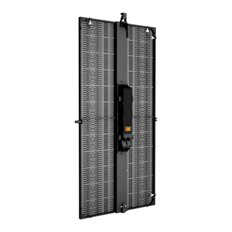
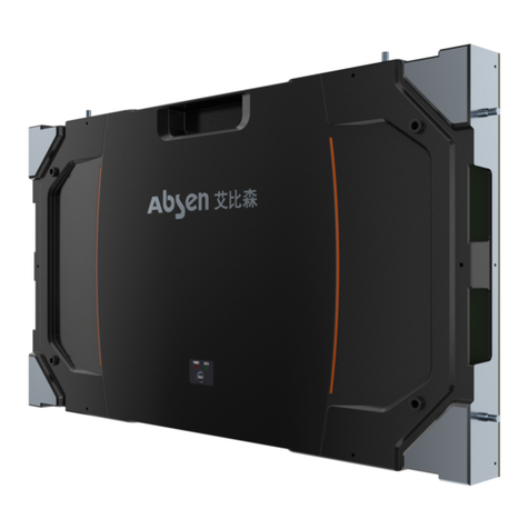
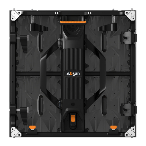
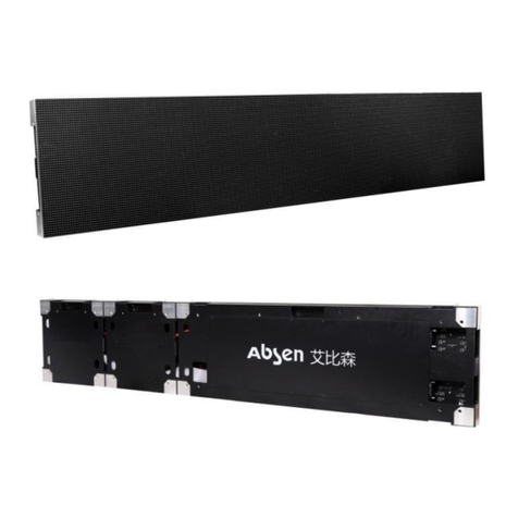
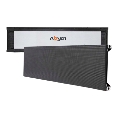
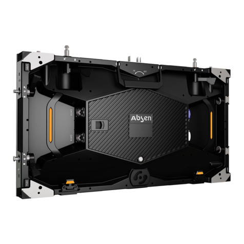
Absen X3 User manual

X3/X5/X7
OUTDOOR & INDOOR
YOUR CHOICE
User Manual
LeadingLEDApplications
High Refresh
Rate
Back-up
Power Supply Easy Installation
ETL
R
FCCPatented Product TUV-CE
High IP Rating
High Brightness Front Servicing

- 01 - X3/X5/X7 User ManualZ
Table of Contents
02-03
04
04
04
05
06
07
09
10
10
11
Safety information
Product Introduction
About X3/X5/X7
Product Dimensions
Product Specifications
Product Value Features
Product Components
Product Assembly
Cabinet Installation and Dissassembly
Rigging Bar Installation
Cabinet Mounting
17
17
18
19
19
20
Product Wiring
Power Cord Cabling Instructions
Cable Wiring Instructions
Maintenance
Preparation Tools
Module Front & Rear Maintenance
Leading LED Applications

X3/X5/X7 User ManualZ - 02 -
Safety Information
The following marks on the product and in this manual indicate important safety measures.
WARNING!
Safety Risk!
Might cause
equipment damage
Or safety risk.
WARNING!
Please read the
manual before
operating.
WARNING!
Dangerous Voltage!
Might cause
equipment damage
or electric shock.
WARNING!
Hot Surface!
Do not touch.
WARNING!
Flammable!
WARNING!
Possible damage
to eyes.
WARNING!
Please read the Safety Measures listed in this section carefully before
installing, switching on, operating and maintenance of this product.
Beware of Electric Shock!
• To prevent electric shock the device must be properly grounded during installation. Do not ignore
using the grounding plug, or else there is a risk of electric shock.
• During a lightning storm, please disconnect the device’s power supply, or provide other suitable
lightning protection. If the equipment is not in use for a long time, please unplug the power cord.
• When performing any installation or maintenance work (e.g. removing the fuses, etc.,) make sure to
turn off the master switch.
• Disconnect AC power when the product is not in use, or before disassembling, or installing the
product.
• The AC power used in this product must comply with local building and electrical codes, and should
be equipped with overload and ground fault protection.
• The main power switch should be installed at a location near the product and should be clearly
visible and easily reached. This way in case of any failure the power can be promptly disconnected.
• Before using this product check all electrical distribution equipment, cables and all connected
devices, and make sure all meet current requirements.
• Use appropriate power cords. Please select the appropriate power cord according to the required
power and current capacity, and ensure the power cord is not damaged, aged or wet. If any
overheating occurs, replace power cord immediately.
• For any other questions, please consult a professional.
Leading LED Applications
WARNING: Be sure to understand and follow all safety guidelines, safety instructions, warnings and
precautions listed in this manual.
This product is for professionals use only!
This product may result in serious injury or death due to fire hazard, electric shock or on dropping.
Please read this manual carefully before installing, powering up, operating and maintenance of this
product.
Follow safety instructions in this manual and on the product. If you have any questions, please seek
help from Absen.
X3/X5/X7 User ManualZ
X3/X5/X7 User Manual
- 03 -
Leading LED Applications
WARNING: Beware of suspended loads.
LED lamps used in the module are sensitive and can be damaged by ESD (electrostatic discharge).
To prevent damage to LED lamps, do not touch when the device is running or switched off.
WARNING: The manufacturer shall not bear any responsibility for any incorrect, inappropriate,
irresponsible or unsafe system installation.
Beware of Fire!
• Use a circuit breaker or fuse protection to avoid fire caused by power supply cables overloading.
• To avoid fire caused by power supply cables overloading, do not connect to the same power supply
point for more than 12 cabinets at a voltage of 100-120V, or 24 cabinets at a voltage of 200-240V.
• Maintain good ventilation around the display screen, controller, power supply and other devices, and
keep a minimum 0.1 meter gap with other objects.
• Do not stick or hang anything on the screen.
• Do not modify the product, do not add or remove parts.
• Do not use the product in case ambient temperature is over 55 ℃.
Beware of Injury!
• Warning: Wear a helmet to avoid injury.
• Ensure any structures used to support, fix and connect the equipment can withstand at least 10
times the weight of all the equipment.
• When stacking products, please hold products firmly to prevent tipping or falling.
• Ensure all components and steel frames are securely installed.
• When installing, repairing, or moving the product, ensure the working area is free of obstacles, and
ensure the working platform is securely and stably fixed.
• In the absence of proper eye protection, please do not look directly at the lit screen from within a 1
meter distance.
• Do not use any optical devices that have converging functions to look at the screen to avoid burning
the eyes.
Product Disposal
• Any component that has a recycling bin label can be recycled.
• For more information on collecting, reusing and recycling, please contact the local or regional waste
management unit.
• Please contact us directly for detailed environmental performance information.

X3/X5/X7 User ManualZ
X3/X5/X7 User Manual - 04 -
Product Introduction
About X3/X5/X7
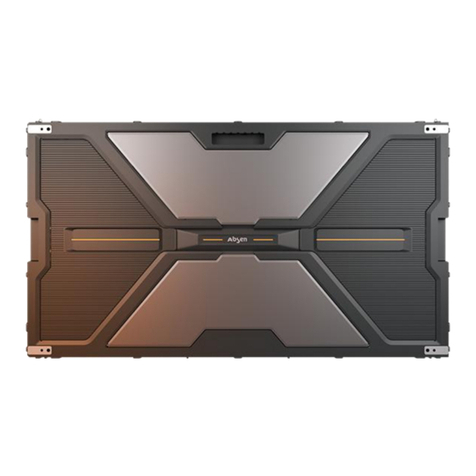
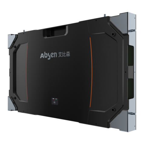
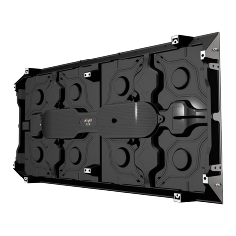
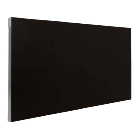
X3/X5/X7 display is a product specially designed for stage rental use. It is mainly used in rental applications for large
concerts, shows, auto shows, business activities&etc., as a medium for video broadcast, information release, and so on.
the product series has 3.9mm,5.2mm,7.8mm pixel pitch, and is a high-definition display for both indoor and outdoor
rental use. The product uses die-cast aluminum cabinet, and the cabinet design is modern, slim and light. The display
has excellent flatness, high quality cabinet and module finish, and high structural strength. The cabinet dimension is:
500 X 562.5 X 94 mm.
Product Dimensions
500mm
562.5mm
94mm
Leading LED Applications

X3/X5/X7 User Manual- 05 -
Product Specifications
Technical Specifications X5X3 X7
Leading LED Applications
Pixel Pitch
Pixels
Panel Resolution
Module Size
Panel Dimensions (WxHxD)
Panel Weight
Panel Material
Brightness
Contrast Ratio
Refresh Rate
Pixel Density
Viewing Angle (horizontal / vertical)
IP Rate (front / rear)
Power (maximum / average)
Input Voltage (AC)
Operating Temperature
SMD1921 SMD2727
Die casting Aluminum Die casting Aluminum Die casting Aluminum
160/90 deg. 160/90 deg. 120/100 deg.
IP65/IP54 IP65/IP54 IP65/IP54
615/205 w/sq.m 555/185 w/sq.m 555/185 w/sq.m
100~240 100~240 100~240
-20~﹢50 -20~﹢50 -20~﹢50
4500nits 5000nits 5000nits
3800:1 4500:1 6800:1
≥1,920 Hz ≥3000 Hz ≥1,920 Hz
65536 Pixels/sq.m 36,864 Pixels/sq.m 16384 Pixels/sq.m
3.9mm 5.2 mm 7.8 mm
SMD2727
250×281.25 mm 250 x 281.25 mm 250×281.25 mm
500×562.5×94 mm 500 x 562.5 x 94 mm 500×562.5×94 mm
10.6kg 10 kg 10 kg
128×144 pixels 96 x 108 pixels 64×72 pixels
Cabinet Installation Type
Maximum Number of
Cabinet for Hanging
Rental/ Fix Rental/ Fix Rental/ Fix
16 16 16

X3/X5/X7 User Manual - 06 -
Product Value Features
• Modular design, magnetic module structure: Module and cabinet frame have modular design and magnetic
modular structure, making product assembly, installation and maintenance as simple as building blocks.
• Independent waterproof module design: Independent waterproof module, ingress protection IP65 / IP54,
suitable for both indoor and outdoor use.
• Dual power supply backup design: When one power supply fails, the other power supply automatically
intervenes, ensuring display’s normal operation is not effected; reliable and worry-free.
• Front and Rear module maintenance: Replacing the module for maintenance takes just 5 seconds; directly
enhances maintenance efficiency by more than 3 times.
• Fast upper and lower installation, left and right, straight and arc splicing: Supports , -5 ˚, 0 ˚, +5˚, +10˚straight
screens or curved splicing, to meet requirements for creative and flexible shapes.
• Excellent display effect: Uses light-trapping mask design techniques; uses black eye black light, with high
contrast ratio of 3000:1.
• Over 5,000nit brightness, above 3,000Hz refresh rate, 15bit grayscale, low-light high grayscale.
• Dual power supply backup design: When one power supply fails, the other power supply automatically
intervenes, ensuring display’s normal operation is not effected; reliable and worry-free.
• High module flatness, good cooling effect: "Pyramid" structure bottom shell design, ensures stable structure,
not easy to deform, and good cabinet flatness.
Leading LED Applications

X3/X5/X7 User Manual- 07 -
Product Components
Rigging Bar
Cabinet cable, 500mm length
Screen cable, 10m length
8
11
8
Leading LED Applications
Single Hoist Rigging Bar
Twin Hoist Rigging Bar

X3/X5/X7 User Manual - 08 -
Cabinet power cord, 500mm length
Screen power cord, 10m length
Note: Input connectors for screen power cord are optional, and based on customers’ requirements, such as triangular
plug, aviation head and connecting terminals, etc.
Cabinet Flight Case (6-in-1)
Inner size: 850 * 550 * 595mm
Leading LED Applications

X3/X5/X7 User Manual
Angle assembly structure
Upper locking base
- 09 -
Product Assembly
Rigging Bar Introduction
Cabinet Introduction
Handle
Angle assembly structure
Handle
Leading LED Applications
Upper-lower connector
Horizontal splicing left-right Inside- outside arc connector
Upper positioning pin

X3/X5/X7 User Manual - 10 -
Leading LED Applications
• Flat Assembly: Place the other rigging bar from top to bottom through M5 shaft, align left and right rigging
bar’ scale to 0˚, and tighten M8 locking screw to complete rigging bar assembly.
Cabinet Installation and Disassembly
Connect the single hoist rigging bar
to the truss or steel structure through this handle
Unlock M8 screw
Step 3: Tighten M8 locking screw
• First, unlock the M8 screw on the rigging bar. First, unlock the M8 screw on the rigging bar.
Step 1: Through M5 shaft
Step 2: Align to 0˚on the scale

X3/X5/X7 User Manual
• Arc Assembly: Place the other rigging bar from top to bottom through M5 shaft, adjust left and right rigging
bar scale to -10˚/-5˚/5˚/10˚angles, tighten M8 locking screw.
• You can install the screen cabinet unit after the rigging bar is installed. First, lift up the spring pin,
and ensure the round hole on the locking plate is aligned with the through hole on the locking plate.
(As shown below)
- 11 -
Leading LED Applications
Step 1: Lift up the spring pin
Cabinet and Rigging Bar Installation
Cabinet Mounting
Step 3:Tighten M8 locking screw
Plane assembly is completed
Arc assembly is completed
Step 1: Through M5 shaft
Step 2: Align to -10˚on the scale
Step 2: Move the locking plate, align the
cross holes on rigging bar with
the locking plate round hole

X3/X5/X7 User Manual
• Lock the handle in the position as shown in the picture. Insert cabinet rigging bar pin into the rigging bar
locking plate hole, and pull the locking plate up to move the rigging bar pin until its straight-edge round
hole locks into the rigging bar pin slot.
- 12 -
Move cabinet connector
to "release" position
Insert the cabinet unit rigging bar
pin into the locking plate hole
Leading LED Applications
Move the locking plate in horizontal
direction, to ensure its straight-edge round
hole locks into the rigging bar pin slot

X3/X5/X7 User Manual
• After the locking plates are locked, rotate the handle lock nut, to lock the unit screen cabinet onto the
rigging bar.
Hold the screen cabinet unit B’s two lifting pins with both hands, insert according to the above method by
aligning to unit screen A’s locking plate hole, and then push the locking plate with both hands, to push the
locking plate straight-edge round hole into the rigging bar pin slot, release both hands from the unit screen,
then rotate the locking nut to lock the two screens.
- 13 -
Leading LED Applications
Horizontal Connection between Cabinets
Rotate the handle nut to tighten,
lock the screen cabinet unit
attached to the rigging bar
Move cabinet connector
to "release" position
Rigging bar and Cabinet installation is completed

X3/X5/X7 User Manual - 14 -
• For assembling left and right cabinet units, insert the left and right connector into the other cabinet unit’s
hole, and rotate the handle 90˚upwards, as shown below.
Leading LED Applications
Step 1:
Insert the rigging bar pin
of cabinet unit into the
locking plate hole
Step 2:
Use hand to push the locking plate,
to make its straight-edge round hole
enter the rigging bar pin slot

V1.0 July 2015
All rights reserved by Shenzhen Absen Optoelectronic Co., Ltd.
Shenzhen Absen Optoelectronic Co., Ltd. reserves the rights to modify contents without any further notice.
Shenzhen Absen Optoelectronic Co., Ltd. Absen Inc.
18-20F Building 3A, Cloud Park, Bantian, Longgang
District, Shenzhen 518129, P.R.China
7120 Lake Ellenor Drive Orlando, Florida
32809, USA
Absen GmbH
Eisenstrasse 5, 65428 Russelsheim (Frankfurt),
Germany
T: +86-755-89747399
F: +86-755-89747599 W: www.absen.com
F: +49 (0) 6142 78935-29W: www.usabsen.com W: www.absen.com
T: +1-407-203-8870
F: +1-407-203-8873

X3/X5/X7 User Manual
Step 2: Rotate to tighten the locking
nut, and lock the cabinet.
• Finally, rotate to tighten the nut to lock the two screens.
• Adjust rigging bar’s mounting angle according to shape requirement, at -10˚/ -5˚/ +5˚/ +10˚optional inside
and outside arc angles.
- 15 -
Leading LED Applications
Arc Connection between Cabinets
Step 1: Turn the handle 90˚
Cabinets’ left and right connection is completed

X3/X5/X7 User Manual
Leading LED Applications
- 16 -
• Complete upper and lower cabinet connections as per instructions in point 4.2.2.
• The left and right cabinets do not need left-right connectors. Simply join the left-right arc connector
according to the rigging bar angle. Follow the appropriate curvature, and turn the arc-shaped connector’s
screw into the corresponding angle screw holes.
This manual suits for next models
2
Table of contents
Other Absen Monitor manuals

Absen
Absen A27 Pro Series User manual

Absen
Absen K Series User manual

Absen
Absen K Plus Series User manual

Absen
Absen N4 User manual

Absen
Absen KLCOB V2 Series User manual

Absen
Absen JP Series User manual

Absen
Absen CR Series User manual

Absen
Absen NX Series User manual

Absen
Absen AX Series User manual

Absen
Absen PL Lite Series User manual