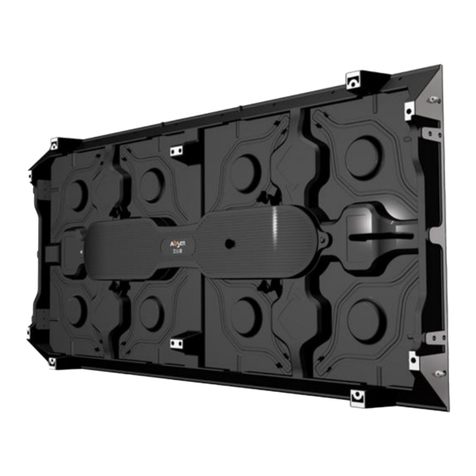
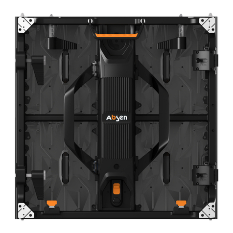
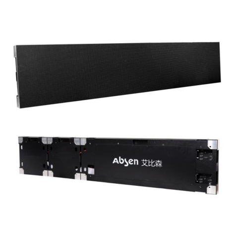
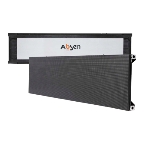
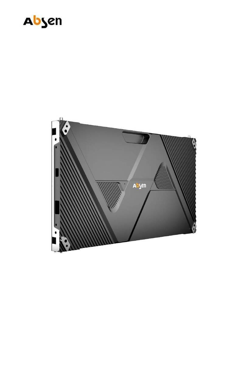
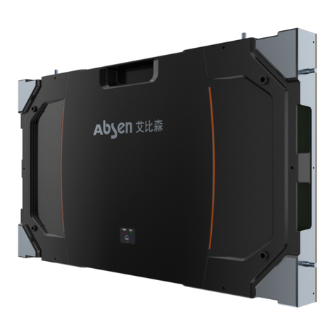
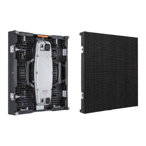
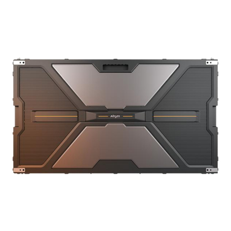
Absen AX Series User manual

AX series User Manual
ST EP
Simple Operation Panel Weight Cooling System Fast Assembly High Brightness Front Servicing High Refre

Table of content
Safety Information 03
Product Introduction 06
About AX series 06
Product Specifications 07
Basic Wiring Overview for Hanging Installation and Stacking Installation
Locking System 09
Product Assembly 11
Hanging Bar/Rigging Bar 15
Service and Maintenance 15
Accessories 19
Flight Cases 20

Safety Information
在安装、供
电、运行、调试本产品之前,请务必阅读本节
The following marks on the product and in this manual indicate important safety
measures.
Warning: Be sure to understand and follow all safety guidelines, safety
instructions, warnings and precautions listed in this manual.
This product is for professionals use only!
This product may result in serious injury or death due to fire hazard,
electric shock or on dropping.
Please read this manual carefully before installing, powering up,
operating and maintenance of this product.
Follow safety instructions in this manual and on the product. If you
have any questions, please seek help from Absen.
WARNING!
Please read the Safety Measures listed in this section carefully before
installing, switching on, operating and maintenance of this product.
WARNING!
Safety Risk!
Might cause
equipment
damage
Or safety risk
WARNING!
Please read the
manual before
operating
WARNING!
Dangerous
Voltage!
Might cause
equipment
damage or
electric shock
WARNING!
Hot Surface!
Do not touch
WARNING!
Flammable!
WARNING!
Possible damage
to eyes

Beware of Electric Shock!
To prevent electric shock the device must be properly grounded during
installation. Do not ignore using the grounding plug, or else there is a
risk of electric shock.
During a lightning storm, please disconnect the device’s power
supply, or provide other suitable lightning protection. If the equipment
is not in use for a long time, please unplug the power cord.
When performing any installation or maintenance work (e.g. removing
the fuses, etc.,) make sure to turn off the master switch.
⚫Disconnect AC power when the product is not in use, or before
disassembling, or installing the product.
⚫The AC power used in this product must comply with local building
and electrical codes, and should be equipped with overload and
ground fault protection.
⚫The main power switch should be installed at a location near the
product and should be clearly visible and easily reached. This way in
case of any failure the power can be promptly disconnected.
⚫Before using this product check all electrical distribution equipment,
cables and all connected devices, and make sure all meet current
requirements.
⚫Use appropriate power cords. Please select the appropriate power
cord according to the required power and current capacity, and
ensure the power cord is not damaged, aged or wet. If any
overheating occurs, replace power cord immediately.
⚫For any other questions, please consult a professional.
Beware of Fire!
⚫Use a circuit breaker or fuse protection to avoid fire caused by power
supply cables overloading.
⚫Maintain good ventilation around the display screen, controller,
power supply and other devices, and keep a minimum 0.1 meter gap
with other objects.
⚫Do not stick or hang anything on the screen.
⚫Do not modify the product, do not add or remove parts.
⚫Do not use the product in case ambient temperature is over 50 ℃.
Beware of Injury!
⚫Warning: Wear a helmet to avoid injury.
⚫Ensure any structures used to support, fix and connect the
equipment, can withstand at least 10 times the weight of all the
equipment.
⚫When stacking products, please hold products firmly to prevent
tipping or falling.
⚫Ensure all components and steel frames are securely installed.
⚫When installing, repairing, or moving the product, ensure the
working area is free of obstacles, and ensure the working platform is
securely and stably fixed.
⚫In the absence of proper eye protection, please do not look directly
at the lit screen from within a 1 meter distance.
⚫Do not use any optical devices that have converging functions to
look at the screen to avoid burning the eyes.
Product Disposal
⚫Any component that has a recycling bin label can be recycled.
⚫For more information on collecting, reusing and recycling, please
contact the local or regional waste management unit.
⚫Please contact us directly for detailed environmental performance
information.
WARNING: Beware of suspended loads.
LED lamps used in the module are sensitive and can be damaged by ESD
(electrostatic discharge). To prevent damage to LED lamps, do not touch
when the device is running or switched off.
WARNING: The manufacturer shall not bear any responsibility for any
incorrect, inappropriate, irresponsible or unsafe system installation.

01 Product Introduction
1. Product
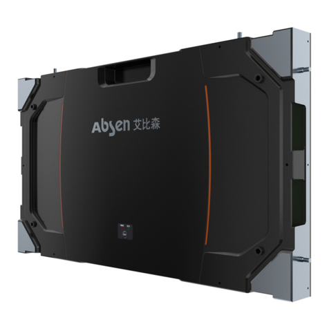
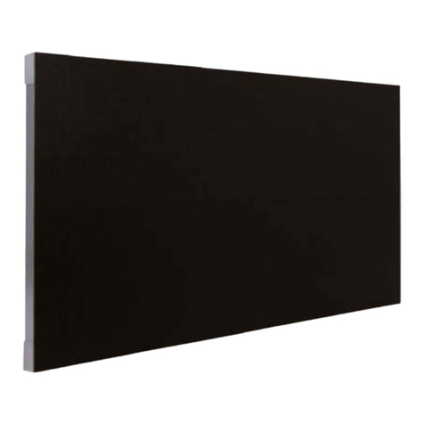
AX series display is a product specially designed for stage rental use. It is mainly used
in rental applications for auto show, TV studio,large concerts, business activities, etc.,
as a medium for video broadcast, information release, and so on.
The product has a 1.58mm and 1.27mm pixel pitch, and is high-definition display for
indoor rental use. The AX series uses die-cast aluminum structure, and the cabinet
design is modern, slim and light. The display has excellent flatness, high quality
cabinet and module finish, and high structural strength. The cabinet dimension is:
610 X 343 X 80mm.

Magnetic
Locking system
Locking system
Locking system
Power box
Protection corner

AX1.5 Product Specifications
Parameters
Specifications
Physical
Parameters
Pixels
IMD 4 in 1 1.58
Pixel Pitch (mm)
1.58
Cabinet Pixels
384×216
Pixel Density (Pixels / m2)
396424
Module size (L ×W ×H)/(mm)
152.5×343
Module size (L ×W ×H)/(mm)
610×343×80
Cabinet Material
Die-cast Aluminum
Cabinet Weight (㎏/Cabinet)
7.8
Electronic
Parameters
Color Processing Depth (Bit)
14
Grayscale
16384
Refresh Rate (Hz)
3840
Drive Mode
1/36
Picture Frame Frequency (Hz)
50/60
Signal Transmission Distance (m)
UTP cable:<100 m; Single-mode fiber:<10 km
Optical
Parameters
Brightness (nit)
800
Horizontal Viewing Angle (°)
160
Vertical Viewing Angle (°)
140
Electrical
Parameters
AC Input Voltage (V)
100~240
AC Input Frequency (Hz)
50/60
Maximum AC Input Power (W/m2)
860
Average AC Input Power (W/m2)
285
Environmental
Parameters
Storage Temperature (˚C)
-40~+60
Working Temperature (˚C)
-10~+40
Storage Temperature (RH)
10%~90% Non-condensing
Working Humidity (RH)
10%~90% Non-condensing
Ingress Protection
IP40/IP21
Product Life (hrs)
100000

Leasing
Product
Installation
Cabinet Installation Method
hanging, stacking
Maximum number of hoisted cabinets
25
AX1.2 Product Specifications
Parameters
Specifications
Physical
Parameters
Pixels
IMD 4 in 1 1.27
Pixel Pitch (mm)
1.27
Cabinet Pixels
480×270
Pixel Density (Pixels / m2)
619414
Module size (L ×W ×H)/(mm)
152.5×343
Module size (L ×W ×H)/(mm)
610×343×80
Cabinet Material
Die-cast Aluminum
Cabinet Weight (㎏/Cabinet)
7.8
Electronic
Parameters
Color Processing Depth (Bit)
14
Grayscale
16384
Refresh Rate (Hz)
3840
Drive Mode
1/46
Picture Frame Frequency (Hz)
50/60
Signal Transmission Distance (m)
UTP cable:<100 m; Single-mode fiber:<10 km
Optical
Parameters
Brightness (nit)
600
Horizontal Viewing Angle (°)
160
Vertical Viewing Angle (°)
140
Electrical
Parameters
AC Input Voltage (V)
100~240
AC Input Frequency (Hz)
50/60
Maximum AC Input Power (W/m2)
650
Average AC Input Power (W/m2)
215
Environmental
Parameters
Storage Temperature (˚C)
-40~+60
Working Temperature (˚C)
-10~+40
Storage Temperature (RH)
10%~90% Non-condensing
Working Humidity (RH)
10%~90% Non-condensing
Ingress Protection
IP40/IP21

Product Life (hrs)
100000
Leasing
Product
Installation
Cabinet Installation Method
hanging, stacking
Maximum number of hoisted cabinets
25
2. Basic Wiring Overview for Hanging Installation and Stacking Installation
Notes:
6 panels high
12 panels high

1、Hanging bars can load a max height of 25panels, and the stacking system can load a max of 15panels.
2、At an input voltage of 220V, one power cable can load 12 panels of AX1.5(AX1.2); at an input voltage of 110V, one
power cable can load 6 panels of AX1.5(AX1.2).
02 Locking System
2.1 Standard Locking
Auto-Lock and Auto-Eject systems
Auto-locking Vertical Lock System With Magnetic Auto-connection For Fast and Easy 1
Man Installation With Ultimate Safty And Pixel Protection.
Auto-ejection Side Lock System Enables Super Fast, East And Convenient Disconnection
Of Panels.
⚫Take out the panel from the flight case
⚫Pressing the four corners “push ”of the box
⚫Auto Retracting corner protector
⚫Panels will be attached together by magnets automatically

⚫Hold the bottom of the Panels upward
⚫Pull the knob of top lock system to lock the Panels
2.1 Horizontal Locking Procedures
Inner and outer curve lock systems
Innovative integrated repositionable curve connection block system maintains the
highest level of alignment accuracy in both flat of curve configuration.
Curve connection blocks are available to support any increment of curve +2.5 degree
concave giving users unlimited design flexibility and control.

03 Product Assembly
3.1 Procedure
Stacking

Hanging
3.2 Hanging Installation
Fix the Hanging Bar on the Truss
Turn the adjustment screw to make the clamps close. The hanging bar should be directly affixed
to the truss.

Connect and assemble tiles.
3.2 Stacking system

3.2 hanging bar
0.61m hanging bar
1.22m hanging bar

04 Service and Maintenance
Module Front Maintenance
1.Take off the failure module

Step1:Attach the vacuum maintenance tool to the module and press the maintenance tool switch
before vacuum for 5 seconds. Pull it vertically and pull the module off the panel.
Step 2:Unload the module safety rope and remove the failure module
Easy Maintenance for Power Box

Step1:Push the switch upwards and turn on the power box.
Step2:After removing 2 pcs screws,remove the recevied card;
Step3: After removing 4 pcs screws,remove the power supply.
05 Accessories

Name:Power Cable
Dimension: 1m
Max Current :16A
Name:long Power Cable
Dimension: 10m
Max Current :16A
Name:Display DATA cable
Dimension: 20m
Name:Panle DATA cabel
Dimension: 1m
Name: Sending card Box
Dimension:
W480×H45×D240mm
Name:Flight case
Dimension:
1036x664x576mm
Max Capacity :8 in 1
Name:Front Maintenance
tool
Name:base stand
Dimension: 0.68m,1.22m
Name: Adjustable Beam
Connector-Different
Dimension: 0.9~1.3M
Name:ladder
Dimension: 0.686m,0.43m
Name: Outrigger
Dimension: 0.8m
Name: Clamp between
the tile and the ladder
06 Flight case
This manual suits for next models
2
Table of contents
Other Absen Monitor manuals

Absen
Absen CR Series User manual

Absen
Absen N Plus Series User manual

Absen
Absen A27 Pro Series User manual

Absen
Absen KLCOB V2 Series User manual

Absen
Absen A27 Plus Series User manual

Absen
Absen HC Series User manual

Absen
Absen K Plus Series User manual

Absen
Absen N4 User manual

Absen
Absen NX Series User manual

Absen
Absen PL Lite Series User manual