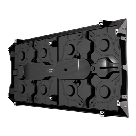
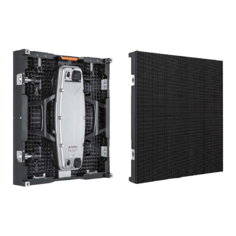
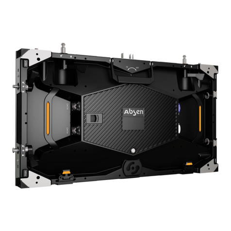
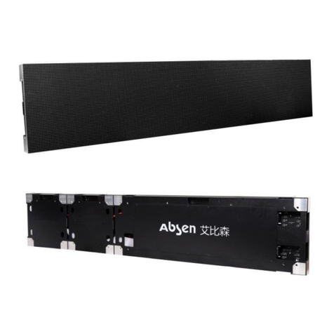
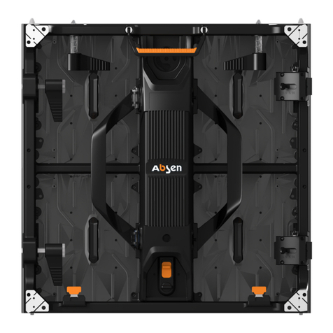
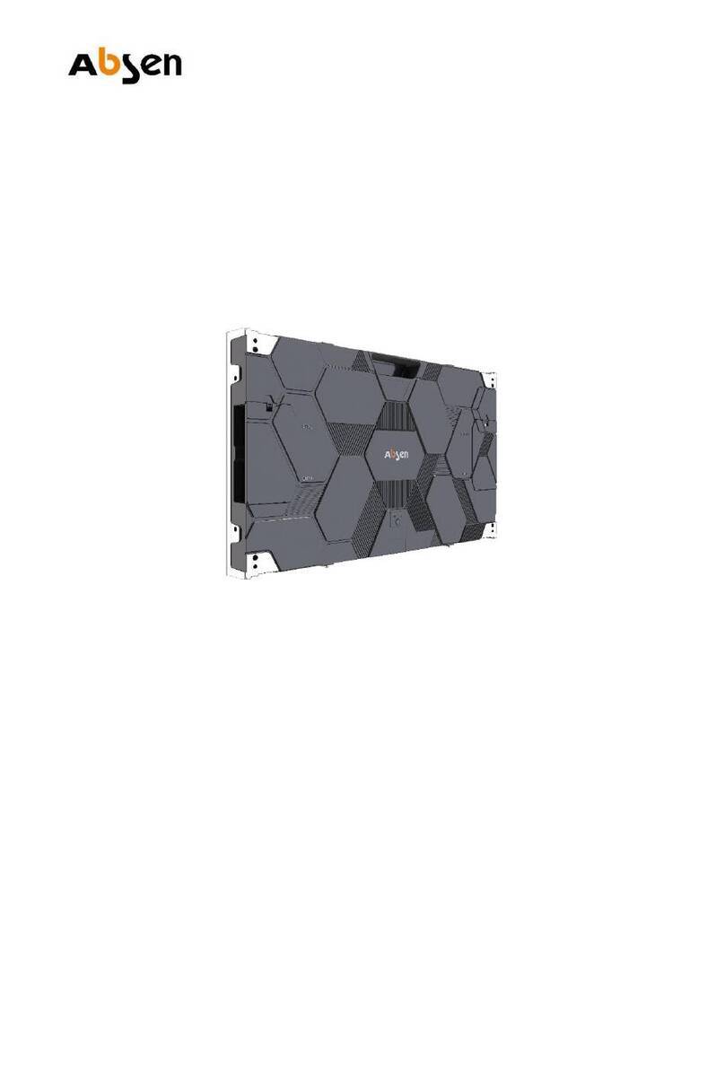
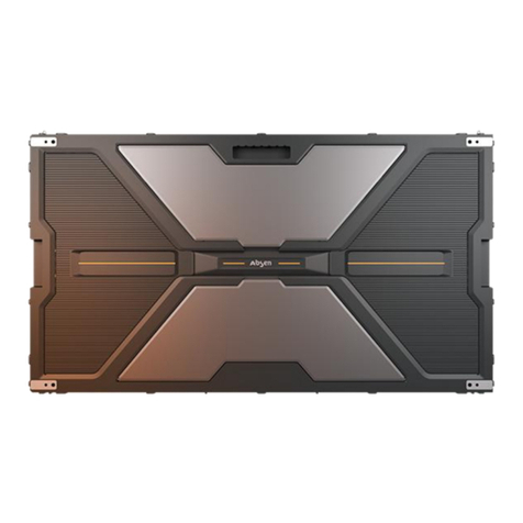
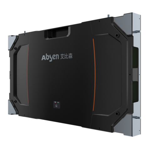
Absen CR Series User manual

LeadingLEDApplications
CRSeriesUserManual
ETL
R
FCC CCC
TUV-CE
16:9HD&4K
pixel-to-pixel
resolution
CrystalView
technology
Powerand
Receivingcard
redundancy
SimpleRear
Maintenance

Leading LED Applications
- 01 -
Table of Contents
CRSeriesUserManual
02-03
04
04
05
06
06
07
08
Safety Information
1、ProductIntroduction
1.1ProductMainFeatures
1.2ProductSpecifications
1.2.1ProductParameter
1.2.2CabinetDimensionDrawing
1.2.3ModuleDimensionDrawing
08
2.1CabinetIntroduction
08-10
2.2ProductStructure/ElectronicComponentsDetails
2、ProductComponents
11-12
3、ProductInstallation
13
14
15-16
17
17
17
4、ProductCabling
4.1PowerCabling
4.2DataCabling
5、Maintenance
5.1PreparationTools
5.2Maintenance
17
5.3TestforShortCircuit

Leading LED Applications
- 02 -
CRSeriesUserManual
Safety Information
The following marks on the product and in this manual indicate important safety measures.
WARNING!
Safety risk! Might
cause equipment
damage or safety risk.
WARNING!
Please read the
manual before
operating.
WARNING!
Dangerous voltage!
Might cause
equipment damage
or electric shock.
WARNING!
Hot surface!
Do not touch.
WARNING!
Flammable! WARNING!
Possible damage
to eyes.
WARNING!
Please read the safety measures listed in this section carefully before installing,
powering on, operating, or doing maintenance on this product.
Beware of Electric Shock!
• To prevent electric shock the device must be properly grounded during installation.Do not ignore
using the grounding plug, or else there is a risk of electric shock.
• During a lightning storm, please disconnect the device’s power supply, or provide other suitable
lightning protection. If the equipment is not in use for a long time, please unplug the power cord.
• When performing any installation or maintenance work (e.g. removing the fuses, etc.,) make sure to
turn off the master switch.
• Disconnect AC power when the product is not in use, or before disassembling, or installing the
product.
• The AC power used in this product must comply with local building and electrical codes, and should
be equipped with overload and ground fault protection.
• The main power switch should be installed at a location near the product and should be clearly
visible and easily reached. This way in case of any failure the power can be promptly disconnected.
• Before using this product check all electrical distribution equipment, cables and all connected
devices, and make sure all meet current requirements.
• Use appropriate power cords. Please select the appropriate power cord according to the required
power and current capacity, and ensure the power cord is not damaged, aged or wet. If any
overheating occurs, replace power cord immediately.
• For any other questions, please consult a professional.
WARNING: Be sure to understand and follow all safety guidelines, safety instructions, warnings
and precautions listed in this manual.
This product is for professional use only!
This product may result in serious injury or death due to fire hazard, electric shock, and crushing
hazard.
Please read this manual carefully before installing, powering up, operating and maintenance of this
product.
Follow safety instructions in this manual and on the product. If you have any questions, please seek
help from Absen.
Leading LED Applications
- 03 - CRSeriesUserManual
WARNING: Beware of suspended loads.
LED lamps used in the module are sensitive and can be damaged by ESD (electrostatic discharge).
To prevent damage to LED lamps, do not touch when the device is running or switched off.
WARNING: The manufacturer shall not bear any responsibility for any incorrect, inappropriate,
irresponsible or unsafe system installation.
Beware of Fire!
• Use a circuit breaker or fuse protection to avoid fire caused by power supply cables overloading.
• Maintain good ventilation around the display screen, controller, power supply and other devices, and
keep a minimum 0.1 meter gap with other objects.
• Do not stick or hang anything on the screen.
• Do not modify the product, do not add or remove parts.
• Do not use the product in case ambient temperature is over 55 ℃.
Beware of Injury!
• Warning: Wear a helmet to avoid injury.
• Ensure any structures used to support, fix and connect the equipment can withstand at least 10
times the weight of all the equipment.
• When stacking products, please hold products firmly to prevent tipping or falling.
• Ensure all components and steel frames are securely installed.
• When installing, repairing, or moving the product, ensure the working area is free of obstacles, and
ensure the working platform is securely and stably fixed.
• In the absence of proper eye protection, please do not look directly at the lit screen from within a 1
meter distance.
• Do not use any optical devices that have converging functions to look at the screen to avoid burning
the eyes.
Product Disposal
• Any component that has a recycling bin label can be recycled.
• For more information on collecting, reusing and recycling, please contact the local or regional waste
management unit.
• Please contact us directly for detailed environmental performance information.

Leading LED Applications
CRSeriesUserManual - 04 -
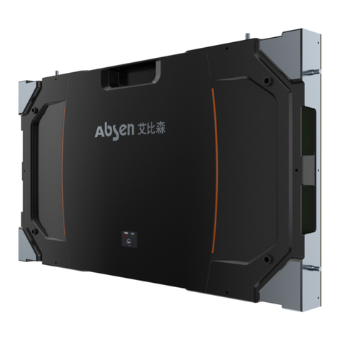
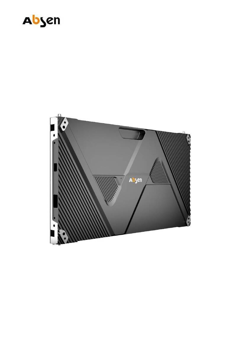
CR series products are indoor fixed and high-definition display line, specially designed for control rooms. The dimension
of its cabinet is 610mm*343mm (precise cabinet dimension is 609.92mmx343.08mm). Each cabinet features a 27.5
inches diagonal with a 16:9 ratio, a 2*2 cabinet layout will make a perfect seamless 55 inch display, which can be used to
replace a traditional LCD video wall with bezels.
This product is primarily used in government, army, large-scale enterprise, control room, command center, conference
room and so on.
1. Product Introduction

Leading LED Applications
CRSeriesUserManual
- 05 -
1.1 Product Main Features
• CR series products features integrated die-cast cabinets using aluminum alloy, actualizing precision with great screen
surface flatness, enhanced heat dissipation and strengthened structural integrity.
• With 16:9 27.5’’ diagonal cabinet design, any 16:9 FHD/4K pixel to pixel screen can be easily assembled. Achieving a
FHD display is as simple as assembling a [4*4] CR1.2 (110’’ diagonal), a [5*5] CR1.5 (137.5’’ diagonal), a [6*6] CR1.9
(165’’ diagonal).
• High gray scale, high refresh rate, high gray scale retention at low brightness setting, great contrast ratio and fantastic
viewing angle. Exhilarating visual performance with great coverage of color space.
• Safety and Stability: The dual-power-supply and dual-receiving-card system ensures safety and stability of the
screens (Single-power-supply and single-receiving-card system is also available), highly advanced designs of circuit
layout and heat dissipation, electromagnetic-compatibility and protection, high-performance power, long service life.
• Total Plug wireless technology: Internal wireless design, hot-swappable module design, pluggable power supply and
receiving card.
• Sequence and Calibration Technology: set up sequence for installation and debugging, detection for malfunction,
automatically identify the signal flow of the screen and each cabinet will get serialized.
• Fan-less design for LED cabinet and power supply: eliminate noise and reducing power consumption, more ener-
gy-efficient.
• Reliable data and power cable design for quick connections.
• External test button and indicator light provide clear product operating status at a glance.
• Absen 3rd Generation Pixel-level Correction (A3C+) support enhancing the image quality and color uniformity.
Automatic readback of calibration data stored on the newly replaced modules.
• Automatic energy-saving mode turns on when display total or partial black screen.

Leading LED Applications
CRSeriesUserManual - 06 -
1.2 Product Specifications
1.2.1 Product Parameter
Remark: Power consumption tolerance: ±15%, it varies from case to case.
Parameters
CR1.9 CR1.5 CR1.4 CR1.2
Physical
Parameters
LED Type BLACK SMD1010 BLACK SMD1010
BLACK SMD1010
BLACK SMD1010
Pixel Pitch (mm)
1.906
1.58
1.46
1.27
Panel Dimensions
(WxHxD)/(mm)
610×343×67
610×343×67
610×343×67
610×343×67
Pixel per Panel
320×180
384×216 416×234 480×270
Panel Weight (kg)
6
6
6
6
Panel Material
Die-cast
Aluminum
Die-cast
Aluminum
Die-cast
Aluminum
Die-cast
Aluminum
Module Dimensions (WxH)/(mm)
152.5×171.5
152.5×171.5 152.5×171.5 152.5×171.5
Optoelectronic
Parameter
Brightness (nit)
800
650
600
600
Refresh Rate (Hz)
1,920 1,920 1,920 1,920
Contrast RaƟo
4,500:1
4,000:1
3,000:1 3,000:1
Color Temperature (K)
6,500
6,500
6,500
6,500
Viewing Angle (H/V)(°)
160/140
160/140
160/140
160/140
Driving Type
1/20
1/24
1/26
1/27
AC OperaƟng Voltage(V)
100~240
100~240
100~240
100~240
Power ConsumpƟon (Max./Avg.)
(W/m²)
610/203
610/203
610/203
610/203
ApplicaƟon
Parameter
Storage Temperature (℃)
﹣
40~
﹢
60
OperaƟng Temperature (℃)
﹣
10~
﹢
40
Storage Humidity (RH)
10
﹪
~90
﹪
OperaƟng Humidity (RH)
10
﹪
~90
﹪
IP RaƟng (Front/Rear)
IP40/IP21
LED LifeƟme (H)
100,000
Module Maintenance Front/Rear
PSU & Others Maintenance
Rear
Panel InstallaƟon Type Stack, Rear InstallaƟon
CerƟficate
TUV-CE+RoHS/ETL+FCC/CCC

Leading LED Applications
CRSeriesUserManual
1.2.2 Cabinet Dimension Drawing
1.2.3 Module Dimension Drawing
- 07 -
NN
NN
NN
NN
NN

Leading LED Applications
CRSeriesUserManual
2. Product Components
2.2 Product Elements
- 08 -
2.1 Product Specifications
Screw
Poweroutput
Testbuttonandindicatorlight
Powerinput
Dowelpin
DATA2
Righthandle
Lefthandle
Screwholes
DATA1
Handle
2.2.1Datacableforverticalconnectionsinbetweenthecabinets,0.5mlong.
8
11
8
2.2.2Datacableforhorizontalconnectionsinbetweenthecabinets,0.8mlong.
8
11
8

Leading LED Applications
CRSeriesUserManual
- 09 -
2.2.3Powercableforverticalconnection,lengthis0.25m:
2.2.6Mainpowercable,lengthis10m:
2.2.7Standardpackage:cartonboxforeachcabinet,packagedsize:710x440x150mm(L*W*H),
weight:about7kg
2.2.4Powercableforhorizontalconnection,lengthis0.8m:
2.2.5Maindatacablefromscreentotheprocessor,lengthis30m;
Notes:MainPowercableissuitableforplugsorterminals.
MEAS:710*440*150mmG.W:KG
QTY: PCS N.W:KG

Leading LED Applications
CRSeriesUserManual - 10 -
2.2.8Connectorandboltforinstallation.
M8x120full-lengththreadedboltStructureconnector
105mm
88mm
16mm
Threadedhole
foradjustingZAxis
Verticalconnectorforthecabinets
Connectorbetweencabinets
Horizontalconnectorforthecabinets
Threadedhole
forfixingcabinet
Modulescrewhole
Holeforfixing
structureconnector
41mm
105mm
88mm
49.5mm

Leading LED Applications
CRSeriesUserManual
This CR series products are suitable for fixed installation on steel frame, like the figure shows below.
Suggested Installation Procedure:
Installing the first two lines of cabinets at the bottom of the steel frame, then install cabinets layer by layer to top.
You need to use cabinet connector plates, structure connectors and screws-M8 to mount the panels on to the
frames.
Notes: You need to keep the space of 42mm between steel frame and cabinets connectors, in case there is no
space for reaching module fixing screws, which brings trouble to dismounting of cabinets and modules.
- 11 -
3. Product Installation
Cabinetconnector 40x40mmstructure

Leading LED Applications
CRSeriesUserManual - 12 -
Notes:Duringtheinstallation,theZ-Axisadjustmentboardisdesignedforadjustingthepositionofthe
cabinets.
SteelStructureConnector
M8X120full-lengththreadedbolt
150
125
42

Leading LED Applications
CRSeriesUserManual
· Preparation before wiring
Before supplying power and signal source to the screen, please check power and data cables connections carefully
and make sure they are wired correctly. Use a multimeter to test the L, N and PE lines in AC power input port and
make sure the tree lines are not short-circuited.
· Power cable connection description
Calculate the maximum power consumption and make sure enough power will be provided. Please consult with your
electrician or power distro manufacturers for specific setup. Input voltage of cabinet is 100-240V/AC. 3X1.5mm2
power supply cable is used to connect the cabinets to the power distros. Maximum 16 cabinets per a 220V circuit,
and 8 cabinets per a 110V circuit..
· Cabinet data ports diagram:
Notes: Single-receiving-card cabinet has two RJ45 as video signal input and output, DATA2 does not need to be
utilized. Double receiving card cabinet have two RJ45 for both DATA1 and DATA2, each with two RJ45 ports used
as signal input and output.
4. Product Cabling
- 13 -
DATA2:RJ45videosignalinput
DATA1:RJ45videosignal

Leading LED Applications
CRSeriesUserManual
16 CR1.5 has a max power consumption of 16 x 0.61 x 0.343 x 520W=1.7kW. Connect the cabinets using the power
jumpers, and use the main power cables to power each circuit.
Note: a main power run will carry a maximum of 16 cabinets per 220V circuit, and 8 cabinets per 110V circuit.
- 14 -
Using4x4CR1.5setupasanexample,seebelowfordataandpowercablingmethods.
Poweroutput
Pilotlamp
Testbutton
Powerinput
4.1 Power Cabling
Input100-240V Longpowerline
Powerline

Leading LED Applications
CRSeriesUserManual
The product uses RJ45 CAT5 data interface with no designated input and output ports. The cabinets are cascaded in
the form of “S” using data jumper cables. Calculate total pixel load based on the resolution of the screen, and cable
the screen accordingly. Each CAT5 port must not exceed 655,360 pixel load as illustrated down below.
4.2.1 Cabling for single-receiving-card version
As for this version, both input and output of signal are for DATA1, and DATA1 have two RJ45 ports which are
identical.
Notes: During installation, cabinet magnet fixed screw helps to adjust the seams between the modules.
- 15 -
4.2 Signal Cabling
Computer
HDMI
USB
RJ45Signalline
Sendingbox

Leading LED Applications
CRSeriesUserManual
4.2.2 Cabling for double-receiving-card version
As for this version, route A is for DATA1, route B is for DATA2. DATA1 and DATA2 both have two identical RJ45
ports.
- 16 -
Computer
HDMI
USB
RJ45signalline
Sengdingbox

Leading LED Applications
CRSeriesUserManual
Preparation tools: Multi-meter, Module front service tools, Screwdriver, etc.
Remove the back cover and HUB board from the back side of the cabinet to access the PCB board as the
modules can be accessed from the front. All the power supply, receiving card, and the HUB board can be
serviced by removing back cover.
After finishing cabling the cabinets, use a multi-meter to test the AC input (L/N/PE) and DC output (VCC/GND) to
determine whether there is a short circuit. If a short circuit has been found, please examine the circuit carefully.
Power up the cabinets only after making sure all the circuits are working properly.
5. Maintenance
- 17 -
5.1 Preparation Tools
5.2 Rear Maintenance
5.3 Test for short circuit
Back cover Power box HUB board Adapter plate
Panel
Light board
Receiving card

V1.0 Aug. 2017
All rights reserved by Shenzhen Absen Optoelectronic Co., Ltd.
Shenzhen Absen Optoelectronic Co., Ltd. reserves the rights to modify contents without any further notice.
This manual suits for next models
5
Table of contents
Other Absen Monitor manuals

Absen
Absen JP Series User manual

Absen
Absen N Plus Series User manual

Absen
Absen HC Series User manual

Absen
Absen K Plus Series User manual

Absen
Absen PL Lite Series User manual

Absen
Absen AX Series User manual

Absen
Absen N4 User manual

Absen
Absen X3 User manual

Absen
Absen NX Series User manual

Absen
Absen KLCOB V2 Series User manual