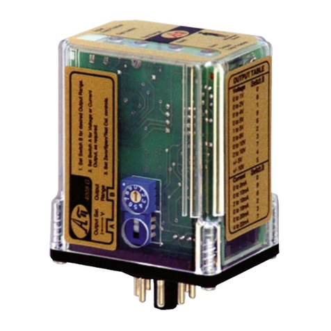
Absolute Process Instruments APD 4008 User manual

Potentiometer Input to DC Transmitters, Isolated, Field Rangeable APD 4008
Input: 100 Ωto 1 MΩPotentiometers, 0 to 90% Offset
Output: 0-1 V to ±10 VDC, or 0-2 mA to 20 mADC
OOne Minute Setup for Hundreds of I/O Ranges
OExternal Switches & Table for Range Selection
ORemovable Plugs for Faster Installation
OFull 1200 V Input/Output/Power Isolation
OInput and Output LoopTracker®LEDs
OFunctional Output Test Button
OSelectable Sink/Source for Current Output
QOver, Under, Out-of-Range Position Monitoring
QRemote Control of Positioning Devices
QSimplify Control of Potentiometer Outputs
Applications
Options–add to end of model number
DF Fast response time, consult factory. DF option will
cause output noise levels to be greater than
standard specifications.
UConformal coating for moisture resistance
Accessory—order as separate line item
API BP4 Spare 4-terminal plug, black
All models are field rangeable
Models can be pre-set to your specifications.
Order APD 4008 D for operation on low voltage power.
Model Input Output Power
APD 4008 Field configurable—specify range if
factory is to set switches
Field configurable—specify range if
factory is to set switches
85-265 VAC, 50/60 Hz or
60-300 VDC
APD 4008 D 9-30 VDC or 10-32 VAC
Description
The APD 4008 accepts a resistance input from potentiometer,
slidewire, linear position, displacement, or rotational devices
and provides an optically isolated DC voltage or current output
that is linearly related to the potentiometer position.
The APD 4008 will accept any potentiometer with a value of
0-100 Ωthrough 0-1 MΩwithout recalibration and without
affecting accuracy. The APD 4008 output can be field-con-
figured via external rotary and slide switches. Offsets and/or
input ranges other than 0 to 100% of the potentiometer range
can also be selected.
The full 3-way (input, output, power) isolation makes this mod-
ule useful for ground loop elimination, common mode signal
rejection or noise pickup reduction.
Sink/Source Output
The APD 4008 has a 20 VDC loop excitation supply for the
output. This power supply can be used to power a passive mA
device. If not required, the APD 4008 output can be wired as
a passive output. Sinking/sourcing versatility allows the APD
4008 to produce a powered or unpowered mA output allowing
it to work with powered or unpowered mA devices.
LoopTracker
API exclusive features include two LoopTracker LEDs (green for
input, red for output) that vary in intensity with changes in the
process input and output signals. These provide a quick visual
picture of your process loop at all times and can greatly aid in
saving time during initial startup and/or troubleshooting.
Output Test
An API exclusive feature includes the test button to provide a
fixed output (independent of the input) when held depressed.
The test output level is potentiometer adjustable from 0 to
100% of output span.
The output test button greatly aids in saving time during initial
startup and/or troubleshooting.
How to Order
Please specify
Model
Input range (if factory is to pre-set)
Output range (if factory is to pre-set)
Options as required
Potentiometer Input
Field selectable ranges via switch settings
See table for complete listing
3 wire connection required
Minimum: 0-100 Ω
Maximum: 0-1 MΩ
Input span: 10-100% of potentiometer range
Input offset: 0-90% in 10% increments
Input Impedance
10 MΩminimum
Common Mode Rejection
120 dB minimum
LoopTracker
Variable brightness LEDs indicate I/O level and status
DC Output Ranges
Field selectable ranges via switch settings
See table for complete listing
Voltage: 0-1 VDC to 0-10 VDC, 10 mA max
Bipolar voltage: ±5 VDC or ±10 VDC
Current: 0-2 mADC to 0-20 mADC
20 V compliance, 1000 Ωat 20 mA
Output Logic
Normal
Output Calibration
Multi-turn zero and span potentiometers
±15% of span adjustment range typical
Output Loop Power Supply
20 VDC nominal, regulated, 25 mADC, <10 mVRMS max. ripple
May be selectively wired for sinking or sourcing mA output
Output Test
Front button sets output to test level when pressed
Potentiometer adjustable 0-100% of span
Output Ripple and Noise
Less than 10 mVRMS
Linearity
Better than ±0.1% of span
Ambient Temperature Range and Stability
–10°C to +60°C operating ambient
Better than ±0.02% of span per °C stability
Response Time
70 milliseconds typical
1 millisecond typical with DF option
Isolation
1200 VRMS minimum
Full isolation: power to input, power to output, input to output
Housing and Connectors
IP 40, requires installation in panel or enclosure
For use in Pollution Degree 2 Environment
Mount vertically to a 35 mm DIN rail
Four 4-terminal removable connectors, 14 AWG max wire size
Power
85-265 VAC, 50/60 Hz or 60-300 VDC, 2 W maximum
D versions: 9-30 VDC or 10-32 VAC 50/60 Hz, 2 W maximum
Removable Plugs
Dimensions
0.89" W x 4.62" H x 4.81" D
22.5 mm W x 117 mm H x 122 mm D
Height includes connectors
Minute
Setup!
1
Universal
Power
Output LoopTracker
LED
Input LoopTracker
LED
Output Test
Function
Front Zero and Span
Connect mA Output
for Sink or Source
Use Any
Potentiometer
Free Factory
I/O Setup!
HHHHHH
HHHHH
HHHHHH
HHHHH
HHHHHH
HHHHH
HHHHHH
HHHHH
HHHHHH
Made in USA
File E145968
85-265 VAC, 60-300 VDC
model only
© 10-18
api-usa.com
1220 American Way Libertyville, IL 60048
Phone: 800-942-0315 Fax: 800-949-7502
ABSOLUTE PROCESS INSTRUMENTS
1 2 3 4
5 6 7 8
9 10 11 12
13 14 15 16
See Wiring
Diagrams on
Next Page

Precautions
WARNING! All wiring must be performed by a qualified electrician
or instrumentation engineer. See diagram for terminal designa-
tions and wiring examples. Consult factory for assistance.
WARNING! Avoid shock hazards! Turn signal input, output, and
power off before connecting or disconnecting wiring, or remov-
ing or installing module.
Précautions
ATTENTION! Tout le câblage doit être effectué par un élec-
tricien ou ingénieur en instrumentation qualifié. Voir le dia-
gramme pour désignations des bornes et des exemples de
câblage. Consulter l'usine pour assistance.
ATTENTION! Éviter les risques de choc! Fermez le signal
d'entrée, le signal de sortie et l'alimentation électrique avant
de connecter ou de déconnecter le câblage, ou de retirer ou
d'installer le module.
Range Selection
See model/serial number label for any applicable options or
custom ranges. It is generally easier to select ranges before
wiring and installation.
See table on next page for module range settings. From the
table, find the rotary switch setting that matches your input
and output range.
For most applications 0-100% of the potentiometer range is
used. The APD 4008 can be set up to use part of the potenti-
ometer range.
Input switch Bcontrols the percent of the potentiometer range
to use.
Input switch Ccontrols the percent of the range offset from zero.
Switch Dcontrols output offset.
Make sure to set the V—I switch for voltage or current output
respectively.
Electrical Connections
Polarity must be observed for output wiring connections. If the
output does not function, check switch settings and wiring polarity.
Input
The potentiometer must be connected to all three signal input
terminals as shown. The APD 4008 utilizes a stable 1 VDC
source to excite the potentiometer.
Output
Polarity must be observed when connecting the signal output.
If your device requires a current input, determine if it provides
power to the current loop or if it must be powered by the APD
module.
Use a multi-meter to check for voltage at your device input
terminals. Typical voltage may be in the range of 9 to 24 VDC.
In this case, wire the device to module terminals 2 and 3.
Module Power
Check model/serial number label for module operating voltage
to make sure it matches available power.
When using DC power, either polarity is acceptable, but for
consistency with similar API products, positive (+) can be wired
to terminal 13 and negative (–) can be wired to terminal 16.
Calibration
Front-mounted Zero and Span potentiometers are used to
calibrate the output to compensate for load and lead variations.
Note: Perform the following calibration procedure any time
switch settings are changed.
1. Apply power to the module and allow a minimum 20 minute
warm up time.
2. Set the input potentiometer to its minimum value to provide
a minimum input to the module.
3. Connect an accurate measurement device to the module
output. Adjust the module’s Zero potentiometer for the
exact minimum output desired. The Zero control should
only be adjusted when the input signal is at its minimum
to produce the corresponding minimum output signal. For
example: 4 mA for a 4-20 mA output or –10 V for a ±10V
output.
4. Set the input potentiometer at its maximum, and then
adjust the module’s Span pot for the exact maximum output
desired. The Span control should only be adjusted when the
input signal is at its maximum. This will produce the cor-
responding maximum output signal. Example: for 4-20 mA
output signal, the Span control will provide adjustment for
the 20 mA or high end of the signal.
5. Repeat adjustments for maximum accuracy.
Output Test Function
The output test potentiometer is factory set to provide approxi-
mately 50% output. When the test button is depressed it will
drive the output side of the loop with a known good signal that
can be used as a diagnostic aid during initial start-up or trou-
bleshooting. When released, the output will return to normal.
The Test Cal. potentiometer can be used to set the test output
to the desired level. It is adjustable from 0 to 100% of the
output span. Press and hold the Test button and adjust the Test
Cal. potentiometer for the desired output level.
Operation
The APD 4008 utilizes a stable 1 VDC source to excite the
potentiometer. This voltage is stabilized against the potentiom-
eter resistance value variations over the entire operating range.
The resulting potentiometer wiper voltage is amplified and
passed through an optical coupler to the output stage where it
is scaled to the desired output range.
The green LoopTracker®input LED provides a visual indication
that a signal is being sensed by the input circuitry of the mod-
ule. It also indicates the input signal strength by changing in
intensity as the process changes from minimum to maximum.
If the LED fails to illuminate, or fails to change in intensity as
the process changes, check the module power or signal input
wiring. Note that it may be difficult to see the LEDs under bright
lighting conditions.
The red LoopTracker output LED provides a visual indication
that the output signal is functioning. It becomes brighter as
the input and the corresponding output change from minimum
to maximum.
For current outputs, the red LED will only light if the output loop
current path is complete. For either current or voltage outputs,
failure to illuminate or a failure to change in intensity as the
process changes may indicate a problem with the module
power or signal output wiring.
Installation and Setup APD 4008
Potentiometer Input Terminal
Full scale or high side of potentiometer 9 (+1 VDC)
Zero or low end of potentiometer 10 (–)
Potentiometer wiper arm 11 65 7 8
13 Power AC or DC +
14 Earth Ground
16 Power AC or DC –
1413 15 16
Test Cal.
Span
Zero
Test
Output
Input
Loop
Tracker
APD 4008
Potentiometer to DC
Isolated Transmitter
Loop
Tracker
109 11 12
9 Full Scale
11 Wiper Arm
10 Minimum
Potentiometer
Type of Device for Output – Terminal + Terminal
Measuring/recording device
accepts a voltage input. 3 (–)
4 (+)
switch E
set to “V”
Device accepts a mA (current)
input and the input is unpow-
ered or passive. APD module
provides the loop power.
3 (–)
4 (+20 V)
switch E
set to “I”
Device accepts a mA (current)
input and provides power to the
current loop.
2 (–)
3 (+)
switch E
set to “I”
21 3 4
Voltage Output
– +
+
–
Voltage
Device
2134
– +
Powered
4-20 mA
Device
Current Sinking Output
switch Eset to “I”
External device provides
loop power
Current Sinking Output
switch E set to “I”
External loop supply
2134
– +
+–
Loop
Power
Source
+
–
4-20 mA
Device
Ri
Cu 60/75°C
conductors
14 AWG
max.
To maintain full isolation
and avoid malfunctions,
do not connect power
supplies in common
with input, output or unit
power.
Do not connect anything
to unused terminals.
12 3 4
5 6 7 8
9 10 11 12
13 14 15 16
Input
Not used
Output
Power
Do not connect
anything to
unused terminals
21 3 4
Current Sourcing Output
Set switch Eto “I”
Passive
Current
Device
+20 V
– +
Not used
Wire terminal
torque
0.5 to 0.6
Nm or
4.4 to 5.3
in-lbs
API maintains a constant effort to upgrade and improve its products.
Specifications are subject to change without notice. See api-usa.com for
latest product information. Consult factory for your specific requirements.
WARNING: This product can expose you to chemicals includ-
ing nickel, which are known to the State of California to cause
cancer or birth defects or other reproductive harm. For more
information go to www.P65Warnings.ca.gov
Module mA output is
unpowered
Module mA output is
unpowered
Module powers mA output loop
Switch Settings APD 4008
APD 4008 Range Selection Table
The module side label lists common ranges. Use the table
below for a complete selection of I/O ranges for your applica-
tion. See the model/serial number label for module information,
options, or if a custom range was specified.
It is generally easier to select ranges before installation.
Switch B controls the percent of potentiometer range to use.
Switch C controls the percent of input offset.
Switch D controls output offset.
Switch E is for voltage or current output selection.
For ranges that fall between the listed ranges use the next
highest setting and trim the output signal with the zero and
span potentiometers.
Output 0-1 V 0-2 V 0-4 V 1-5 V 0-5 V 0-8 V 2-10 V 0-10 V ±5 V ± 10 V 0-2 mA 0-4 mA 0-8 mA 2-10 mA 0-10 mA 0-16 mA 4-20 mA 0-20 mA
Switches BCDE BCDE BCDE BCDE BCDE BCDE BCDE BCDE BCDE BCDE BCDE BCDE BCDE BCDE BCDE BCDE BCDE BCDE
Input
0-100% 000V 008V 001V 006V 009V 002V 007V 003V 004V 005V 000I 008I 001I 006I 009I 002I 007I 003I
10-100% 910V 918V 911V 916V 919V 912V 917V 913V 914V 915V 910I 918I 911I 916I 919I 912I 917I 913I
0-90% 900V 908V 901V 906V 909V 902V 907V 903V 904V 905V 900I 908I 901I 906I 909I 902I 907I 903I
20-100% 820V 828V 821V 826V 829V 822V 827V 823V 824V 825V 820I 828I 821I 826I 829I 822I 827I 823I
10-90% 810V 818V 811V 816V 819V 812V 817V 813V 814V 815V 810I 818I 811I 816I 819I 812I 817I 813I
0-80% 800V 808V 801V 806V 809V 802V 807V 803V 804V 805V 800I 808I 801I 806I 809I 802I 807I 803I
30-100% 730V 738V 731V 736V 739V 732V 737V 733V 734V 735V 730I 738I 731I 736I 739I 732I 737I 733I
20-90% 720V 728V 721V 726V 729V 722V 727V 723V 724V 725V 720I 728I 721I 726I 729I 722I 727I 723I
10-80% 710V 718V 711V 716V 719V 712V 717V 713V 714V 715V 710I 718I 711I 716I 719I 712I 717I 713I
0-70% 700V 708V 701V 706V 709V 702V 707V 703V 704V 705V 700I 708I 701I 706I 709I 702I 707I 703I
40-100% 640V 648V 641V 646V 649V 642V 647V 643V 644V 645V 640I 648I 641I 646I 649I 642I 647I 643I
30-90% 630V 638V 631V 636V 639V 632V 637V 633V 634V 635V 630I 638I 631I 636I 639I 632I 637I 633I
20-80% 620V 628V 621V 626V 629V 622V 627V 623V 624V 625V 620I 628I 621I 626I 629I 622I 627I 623I
10-70% 610V 618V 611V 616V 619V 612V 617V 613V 614V 615V 610I 618I 611I 616I 619I 612I 617I 613I
0-60% 600V 608V 601V 606V 609V 602V 607V 603V 604V 605V 600I 608I 601I 606I 609I 602I 607I 603I
50-100% 550V 558V 551V 556V 559V 552V 557V 553V 554V 555V 550I 558I 551I 556I 559I 552I 557I 553I
40-90% 540V 548V 541V 546V 549V 542V 547V 543V 544V 545V 540I 548I 541I 546I 549I 542I 547I 543I
30-80% 530V 538V 531V 536V 539V 532V 537V 533V 534V 535V 530I 538I 531I 536I 539I 532I 537I 533I
20-70% 520V 528V 521V 526V 529V 522V 527V 523V 524V 525V 520I 528I 521I 526I 529I 522I 527I 523I
10-60% 510V 518V 511V 516V 519V 512V 517V 513V 514V 515V 510I 518I 511I 516I 519I 512I 517I 513I
0-50% 500V 508V 501V 506V 509V 502V 507V 503V 504V 505V 500I 508I 501I 506I 409I 502I 507I 503I
60-100% 460V 468V 461V 466V 469V 462V 467V 463V 464V 465V 460I 468I 461I 466I 469I 462I 467I 463I
50-90% 450V 458V 451V 456V 459V 452V 457V 453V 454V 455V 450I 458I 451I 456I 459I 452I 457I 453I
40-80% 440V 448V 441V 446V 449V 442V 447V 443V 444V 445V 440I 448I 441I 446I 449I 442I 447I 443I
30-70% 430V 438V 431V 436V 439V 432V 437V 433V 434V 435V 430I 438I 431I 436I 439I 432I 437I 433I
20-60% 420V 428V 421V 426V 429V 422V 427V 423V 424V 425V 420I 428I 421I 426I 429I 422I 427I 423I
10-50% 410V 418V 411V 416V 419V 412V 417V 413V 414V 415V 410I 418I 411I 416I 419I 412I 417I 413I
0-40% 400V 408V 401V 406V 409V 402V 407V 403V 404V 405V 400I 408I 401I 406I 409I 402I 407I 403I
70-100% 370V 378V 371V 376V 379V 372V 377V 373V 374V 375V 370I 378I 371I 376I 379I 372I 377I 373I
60-90% 360V 368V 361V 366V 369V 362V 367V 363V 364V 365V 360I 368I 361I 366I 369I 362I 367I 363I
50-80% 350V 358V 351V 356V 359V 352V 357V 353V 354V 355V 350I 358I 351I 356I 359I 352I 357I 353I
40-70% 340V 348V 341V 346V 349V 342V 347V 343V 344V 345V 340I 348I 341I 346I 349I 342I 347I 343I
30-60% 330V 338V 331V 336V 339V 332V 337V 333V 334V 335V 330I 338I 331I 336I 339I 332I 337I 333I
20-50% 320V 328V 321V 326V 329V 322V 327V 323V 324V 325V 320I 328I 321I 326I 329I 322I 327I 323I
10-40% 310V 318V 311V 316V 319V 312V 317V 313V 314V 315V 310I 318I 311I 316I 319I 312I 317I 313I
0-30% 300V 308V 301V 306V 309V 302V 307V 303V 304V 305V 300I 308I 301I 306I 309I 302I 307I 303I
80-100% 280V 288V 281V 286V 289V 282V 287V 283V 284V 285V 280I 288I 281I 286I 289I 282I 287I 283I
70-90% 270V 278V 271V 276V 279V 272V 277V 273V 274V 275V 270I 278I 271I 276I 279I 272I 277I 273I
60-80% 260V 268V 261V 266V 269V 262V 267V 263V 264V 265V 260I 268I 261I 266I 269I 262I 267I 263I
50-70% 250V 258V 251V 256V 259V 252V 257V 253V 254V 255V 250I 258I 251I 256I 259I 252I 257I 253I
40-60% 240V 248V 241V 246V 249V 242V 247V 243V 244V 245V 240I 248I 241I 246I 249I 242I 247I 243I
30-50% 230V 238V 231V 236V 239V 232V 237V 233V 234V 235V 230I 238I 231I 236I 239I 232I 237I 233I
20-40% 220V 228V 221V 226V 229V 222V 227V 223V 224V 225V 220I 228I 221I 226I 229I 222I 227I 223I
10-30% 210V 218V 211V 216V 219V 212V 217V 213V 214V 215V 210I 218I 211I 216I 219I 212I 217I 213I
0-20% 200V 208V 201V 206V 209V 202V 207V 203V 204V 205V 200I 208I 201I 206I 209I 202I 207I 203I
90-100% 190V 198V 191V 196V 199V 192V 197V 193V 194V 195V 190I 198I 191I 196I 199I 192I 197I 193I
80-90% 180V 188V 181V 186V 189V 182V 187V 183V 184V 185V 180I 188I 181I 186I 189I 182I 187I 183I
70-80% 170V 178V 171V 176V 179V 172V 177V 173V 174V 175V 170I 178I 171I 176I 179I 172I 177I 173I
60-70% 160V 168V 161V 166V 169V 162V 167V 163V 164V 165V 160I 168I 161I 166I 169I 162I 167I 163I
50-60% 150V 158V 151V 156V 159V 152V 157V 153V 154V 155V 150I 158I 151I 156I 159I 152I 157I 153I
40-50% 140V 148V 141V 146V 149V 142V 147V 143V 144V 145V 140I 148I 141I 146I 149I 142I 147I 143I
30-40% 130V 138V 131V 136V 139V 132V 137V 133V 134V 135V 130I 138I 131I 136I 139I 132I 137I 133I
20-30% 120V 128V 121V 126V 129V 122V 127V 123V 124V 125V 120I 128I 121I 126I 129I 122I 127I 123I
10-20% 110V 118V 111V 116V 119V 112V 117V 113V 114V 115V 110I 118I 111I 116I 119I 112I 117I 113I
0-10% 100V 108V 101V 106V 109V 102V 107V 103V 104V 105V 100I 108I 101I 106I 109I 102I 107I 103I

Installation APD 4008
2
Removal
Avoid shock hazards! Turn signal input, output, and power off
before removing module.
1. Push up on bottom back of module.
2. Tilt front of module downward to release Upper Mount from
top edge of DIN rail.
3. The module can now be removed
from the DIN rail.
1
3. Push front of module
upward until Upper Mount
snaps into place.
1. Tilt front of module down-
ward and position against
DIN rail.
2. Clip Lower Mount to bot-
tom edge of DIN rail.
Installation
1
2
3
Mounting to a DIN Rail
Install module vertically on a 35 mm DIN rail in a protective
enclosure away from heat sources. Do not block air flow. Allow
1" (25 mm) above and below housing vents for air circulation.
Precautions
WARNING! Avoid shock hazards! Turn signal input, output, and
power off before connecting or disconnecting wiring, or remov-
ing or installing module.
Spring Clip
Upper Mount
Lower Mount
B C D E
Connections
3
4
9
10
11
13
16
Term. # Signal
Sig. Out –
Sig. Out +
Full Scale
Minimum
Wiper Arm
Power +
Power –
®
APD 4008
Potentiometer to DC Isolated Transmitter
Output
VI
Input OutputOffset
Input Switch ‘B’
Span Position
100%
90%
80%
70%
60%
50%
40%
30%
20%
1
0%
0
9
8
7
6
5
4
3
2
1
Offset Switch ‘C’
Offset Position
0%
10%
20%
30%
40%
50%
60%
70%
80%
90%
0
1
2
3
4
5
6
7
8
9
Output Switch ‘D’
Current Position
0 to 2mA
0 to 4mA
0 to 8mA
0 to 10mA
2 to 10mA
0 to 16mA
0 to 20mA
4 to 20mA
0
8
1
9
6
2
3
7
Output Switch ‘D’
Voltage Position
0 to 1V
0 to 2V
0 to 4V
0 to 5V
1 to 5V
0 to 8V
0 to 10V
2 to 10V
+/- 5V
+/- 10V
0
8
1
9
6
2
3
7
4
5
For more Details and Instructions see Data Sheet
1. Set Switches B/C/D for desired Input / Output ranges.
2. Set Switch E for Voltage or Current as required.
3. Set Zero / Span / Test Cal. Controls
Example: 25-75%
IN, 4-20mA OUT:
Set switch “B” to 5;
“C” to 2; “D” to 7
800-942-0315
www.api-usa.com
4
C
0
8
E
2
A
6
3
F
B
7
5
9
D
1
3
2
0
5
1
6
4
9
7
8
4
C
0
8
E
2
A
6
3
F
B
7
5
9
D
1
This manual suits for next models
1
Other Absolute Process Instruments Measuring Instrument manuals

Absolute Process Instruments
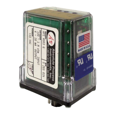
Absolute Process Instruments API 4003 G I User manual

Absolute Process Instruments
Absolute Process Instruments Cecomp F16AD User manual

Absolute Process Instruments
Absolute Process Instruments Cecomp Test+ CTP3B User manual

Absolute Process Instruments
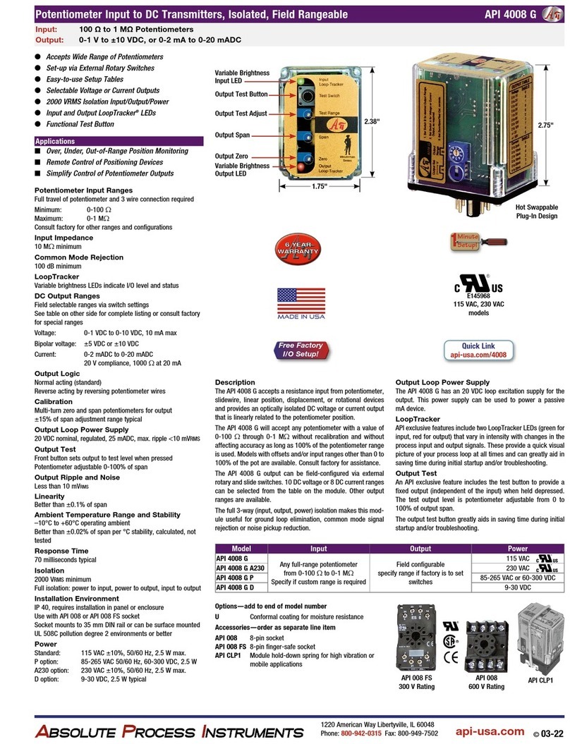
Absolute Process Instruments API 4008 G User manual

Absolute Process Instruments
Absolute Process Instruments Cecomp DPG2000B Series User manual

Absolute Process Instruments
Absolute Process Instruments API 4008 G User manual

Absolute Process Instruments
Absolute Process Instruments Cecomp F20B User manual