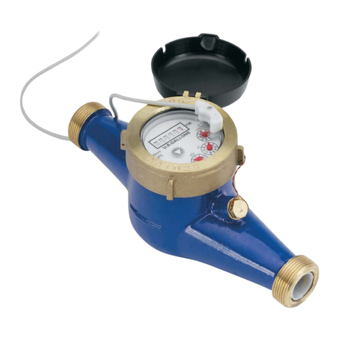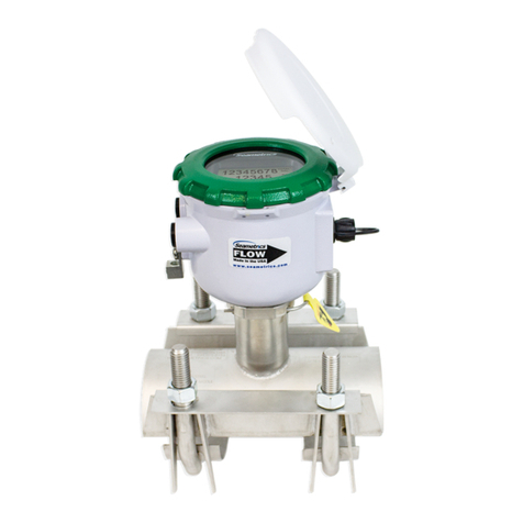
Position. MD-Series meters should be installed hori-
zontally with the register up. Vertical mounting will result
in some degree of under-measurement and shortened
life of the bearings.
Couplings. Couplings are included with each meter.
Theseprovidemale NPT threads the same nominal size
as the meter. The threads on the end of the meter are
IPSstraight threads one size bigger thanthe meter size.
It is possible to thread a standard pipe coupling directly
onto the meter for close coupling, but the meter cou-
plingsaremuch preferable because they provide a union
connectionformeterservice. Be sure to use the included
gasket between the end of the meter and the coupling.
Inlet Conditions. Noupstreamstraightpipeisrequired.
A strainer is built in to protect from solids, and should be
periodically cleaned.
Air Bleed. When the meter is first installed, trapped air
should be removed. To do this, loosen the meter cou-
plings slightly and rotate the meter to an inverted
position. Allow water to flow, then rotate the meter
back to an upright position and tighten.
Connections. MDEandMDR sensors are supplied with
a color coded output cable. See the diagram for color
codes and polarity. Optional connectors can be ordered
to plug directly into a SeaMetrics control or a specific
brand of metering pump.
Pulse Output. Both MDE and MDR sensors respond to
a magnet which rotates on the face of the meter under
the lens. The sensor turns on and off once each time
the magnet passes under it. Sensors are designed for
electroniccontrolloads,andshouldnotbeusedto switch
power loads or line voltages. See maximum current and
voltage ratings, under Specifications.
Maintenance
SeaMetrics recommends all service to be performed by
authorized distributor or factory to maintain the integrity
of the protective tamper-proof wire-and-seal.
Inlet Strainer. Clean the strainer yearly, or as required,
depending on water condition. Pull out the strainer or
backflush the meter to loosen trapped particulates.
Calibration. Meters used for billing or billing exemption
may be regulated by state or local authorities. New
metersare factory-tested to meet theAWWAC-708Multi-
Jet Meter accuracy specification. Some states
requireretestingatvariousintervals,typicallyeightyears
for 3/4" meters, six for 1", and four for 1-1/2" and 2".
Meters used for control should be tested every 5-10
years. Testing can be done by local meter shops autho-
rized for this purpose, or can be done by the factory.
Please contact SeaMetrics before sending meter in for
calibration or servicing.
Internal Parts Replacement. All of the internal parts of
an MD-Series meter lift out as a unit, after the top has
beenunscrewed.Thelens can then beremoved and the
internal assembly lifted out. The three pieces of the
assembly can be separated by hand.
Excessiveflowcancausebreakage. Compare maximum
flow with the flow rating table.
Changing Pulse Rates. After removing the meter top,
lift off the center magnet to expose the gears. If the only
change required is moving the drive gear (for example
from one gallon/pulse to ten gallons/pulse), gently pull
the drive gear off its shaft. Remove the pointer on the
target shaft and push the drive gear onto the target shaft
as far as it will go. Put the pointer on the vacant shaft
and push on.
If a different gear set is required, follow the same proce-
dure, replacing rather than moving the drive gear. To
install a drive gear on another shaft, remove the pointer
and then press the gear down until it bottoms. Use the
pulse rate chart to determine the position.
2 of 4
(BLACK) Power (-)
(BROWN) Common
(WHITE) Signal
(WHITE) N.O.
(RED) Power (+) 6-24 VDC
sensor connection
MDRsensor connection
MDE
Installation
These water meters are not
recommended for installation
indoors or anywhere leakage
may cause damage.
WARNING
DO NOT INSTA
meter in overhead
Indoor piping or where
leakage
may cause damage
