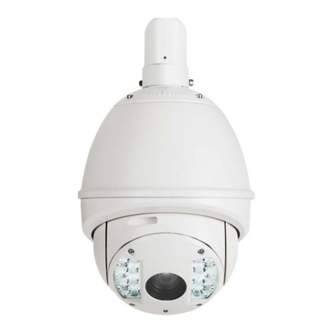
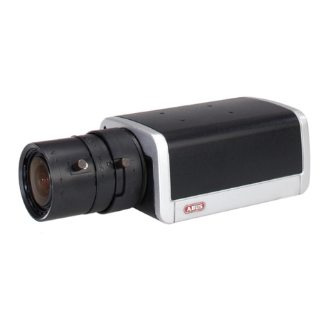
Abus IPCA22500 User manual

IPCA22500 / IPCA32500 / IPCA52000 /
IPCA62500 / IPCA62505 /
IPCA72500 / IPCA72505
Version 10/2017
English translation of the original German user manual. Retain for future reference.

55
Introduction
Dear customer,
Thank you for purchasing this product.
IPCA22500
This device complies with the requirements of the following EU directives: the EMC Directive
2014/30/EU and the RoHS Directive 2011/65/EU. The full EU Declaration of Conformity text can
be found at: www.abus.com/product/IPCA22500
IPCA32500
This device complies with the requirements of the following EU directives: the EMC Directive
2014/30/EU and the RoHS Directive 2011/65/EU. The full EU Declaration of Conformity text can
be found at: www.abus.com/product/IPCA32500
IPCA52000
This device complies with the requirements of the following EU directives: the EMC Directive
2014/30/EU and the RoHS Directive 2011/65/EU. The full EU Declaration of Conformity text can
be found at: www.abus.com/product/IPCA52000
IPCA62500
This device complies with the requirements of the following EU directives: the EMC Directive
2014/30/EU and the RoHS Directive 2011/65/EU. The full EU Declaration of Conformity text can
be found at: www.abus.com/product/IPCA62500
IPCA62505
This device complies with the requirements of the following EU directives: the EMC Directive
2014/30/EU and the RoHS Directive 2011/65/EU. The full EU Declaration of Conformity text can
be found at: www.abus.com/product/IPCA62505
IPCA72500
This device complies with the requirements of the following EU directives: the EMC Directive
2014/30/EU and the RoHS Directive 2011/65/EU. The full EU Declaration of Conformity text can
be found at: www.abus.com/product/IPCA72500
IPCA72505
This device complies with the requirements of the following EU directives: the EMC Directive
2014/30/EU and the RoHS Directive 2011/65/EU. The full EU Declaration of Conformity text can
be found at: www.abus.com/product/IPCA72505
To ensure this condition is maintained and that safe operation is guaranteed, it is your obligation
to observe this user manual.
Read the entire user manual carefully before putting the product into operation, and pay attention
to all operating instructions and safety information.
All company names and product descriptions are trademarks of the corresponding owner.
All rights reserved.
If you have any questions, please contact your specialist installation contractor or
specialist dealer.

56
Disclaimer
This user manual has been produced with the greatest of care. Should you discover any
missing information or inaccuracies, please let us know about them.
ABUS Security-Center GmbH & Co. KG does not accept any liability for technical and
typographical errors, and reserves the right to make changes to the product and user manuals
at any time and without prior warning.
ABUS Security-Center GmbH is not liable or responsible for any direct or indirect damage
resulting from the installation, performance and use of this product. No forms of guarantee are
accepted for the contents of this document.

57
Important safety information
All guarantee claims are invalid in the event of damage caused by non-compliance
with this user manual. We cannot be held liable for resulting damage.
In the event of material or personal damage caused by improper operation or non-
compliance with the safety information, we cannot be held liable. All guarantee claims
are void in such cases.
Dear customer,
The following safety information and hazard notes are not only intended to protect your health but
also to protect the device from damage. Please read the following points carefully:
There are no components inside the product that require maintenance by the operator. Opening or
dismantling the product invalidates the CE certification and guarantee claims/warranty.
The product may be damaged if it is dropped, even from a low height.
Avoid the following adverse conditions during operation:
Moisture or excess humidity
Extreme heat or cold
Direct sunlight
Dust or flammable gases, vapours or solvents
Strong vibrations
Strong magnetic fields (e.g. next to machines or loudspeakers)
The camera must not be installed on unstable surfaces.
General safety information:
Do not leave packaging material lying around. Plastic bags, sheeting, polystyrene packaging, etc.
can pose a danger to children if played with.
The video surveillance camera contains small parts which could be swallowed and should be kept
out of reach of children for safety reasons.
Do not insert any objects into the device through the openings.
Only use replacement devices and accessories that are approved by the manufacturer. Do not
connect any non-compatible products.
Please pay attention to the safety information and user manuals for the other connected devices.
Check the device for damage before putting it into operation. Do not put the device into operation if
you detect any damage.
Adhere to the operating voltage limits specified in the technical data. Higher voltages could destroy
the device and pose a health risk (electric shock).
When installing the device in an existing video surveillance system, ensure that all devices
have been disconnected from the mains power circuit and low-voltage circuit.
If in doubt, have a specialist technician carry out assembly, installation and connection of the
device. Improper or unprofessional work on the power supply system or domestic installation
puts both you and other persons at risk.
Connect the installations so that the mains power circuit and low-voltage circuit always run
separately
from each other. They should not be connected at any point or become connected as a
result of a malfunction.

58
Contents
1. INTENDED USE ................................................................................................................... 60
2. EXPLANATION OF SYMBOLS ........................................................................................... 60
3. SCOPE OF DELIVERY ........................................................................................................ 60
4. FEATURES AND FUNCTIONS ............................................................................................ 62
5. DEVICE DESCRIPTION ....................................................................................................... 63
5.1 OVERVIEW – MODEL NUMBERS ............................................................................................. 63
5.2 UNPACKING THE DEVICE ........................................................................................................ 63
5.3 OVERVIEW OF CONNECTIONS, CONTROL ELEMENTS, FRONT/BACK .......................................... 64
6. INSTALLATION ................................................................................................................... 70
6.2 LAYING THE CABLES .............................................................................................................. 70
6.3 POWER SUPPLY .................................................................................................................... 71
6.4 ATTACHING THE NETWORK CABLE.......................................................................................... 72
6.5 ALIGNING THE CAMERA ......................................................................................................... 72
6.6 ZOOM AND FOCUS SETTINGS ................................................................................................. 72
6.7 ATTACHING THE OPTIONAL CONNECTING CABLE FOR IPCA32500, IPCA72500 AND IPCA72505
.................................................................................................................................................. 73
6.8 SWITCHING INPUT AND SWITCHING OUTPUT ........................................................................... 73
6.9 STATUS INDICATORS ............................................................................................................. 74
6.10 CONNECTION INSTRUCTIONS FOR AUDIO INPUT/OUTPUT ....................................................... 74
6.11 RESTORING FACTORY SETTINGS (RESET) ............................................................................. 75
6.12 CHANGING THE DOME ......................................................................................................... 75
6.13 EXCHANGE OF MICROSD CARD (ONLY IPCA32500, IPCA72500, IPCA72505)..................... 76
7. INITIAL START-UP .............................................................................................................. 77
7.1 USING THE ABUS IP INSTALLER FOR CAMERA SEARCH .......................................................... 77
7.2 ACCESSING THE NETWORK CAMERA USING A WEB BROWSER .................................................. 78
7.2.1 GENERAL INSTRUCTIONS FOR USING THE SETTINGS PAGES ................................................. 78
7.3 INSTALLING A VIDEO PLUGIN .................................................................................................. 78
7.4 HOMEPAGE (LOGIN PAGE) ..................................................................................................... 80
7.5 USER ACCOUNTS AND PASSWORDS ....................................................................................... 81
8. USER MENU "USER" .......................................................................................................... 82
9. VIEW AND CONFIGURATION MENU USER "MASTER" .................................................. 84
9.1 DEACTIVATE/ACTIVATE INSTALLER ACCESS ............................................................................ 86
9.2 DISPLAYING/DOWNLOADING VIDEO FROM THE INTERNAL MEMORY ........................................... 87
10. VIEW AND CONFIGURATION MENUS USER "INSTALLER" ........................................... 88
10.1 LIVE VIEW ........................................................................................................................... 88
10.2 INFO PAGE .......................................................................................................................... 90
10.3 SETUP WIZARD ................................................................................................................... 91
10.4 ADVANCED CAMERA SETTINGS ............................................................................................ 91
10.4.1 VIDEO ............................................................................................................................. 91
10.4.1.1 GENERAL ..................................................................................................................... 91
10.4.1.2 DAY PROFILE ................................................................................................................ 92
10.4.1.3 NIGHT PROFILE ............................................................................................................. 92
10.4.1.4 DAY/NIGHT SWITCHING .................................................................................................. 92
10.4.1.5 PRIVACY MASKING ........................................................................................................ 93
10.4.1.6 VIDEO STREAM SETTINGS .............................................................................................. 94
10.4.1.7 NETWORK LOSS RECORDING ......................................................................................... 95
10.4.2 NETWORK ....................................................................................................................... 97
59
10.4.2.1 IPV4 SETTINGS ............................................................................................................. 97
10.4.2.2 PORTS ......................................................................................................................... 97
10.4.2.3 DDNS .......................................................................................................................... 97
10.4.2.4 HTTPS ........................................................................................................................ 98
10.4.2.5 SMTP/EMAIL ................................................................................................................ 98
10.4.2.6 MULTICAST ................................................................................................................... 98
10.4.2.7 ONVIF ......................................................................................................................... 98
10.4.2.8 FTP SERVER ................................................................................................................ 98
10.4.3 OVERLAY TEXT ................................................................................................................ 99
10.4.4 DATE/TIME ....................................................................................................................... 99
10.4.5 SYSTEM ........................................................................................................................ 100
10.4.5.1 GENERAL ................................................................................................................... 100
10.4.5.2 FIRMWARE/RESET ...................................................................................................... 100
10.4.5.3 LOG FILE .................................................................................................................... 100
10.4.6 MOTION DETECTION ....................................................................................................... 100
10.4.7 ALARM MANAGER ........................................................................................................... 101
10.4.8 AUDIO ........................................................................................................................... 102
10.4.9 USER ............................................................................................................................ 102
10.4.10 SERVICE ...................................................................................................................... 102
11. MAINTENANCE AND CLEANING ..................................................................................... 103
11.1 FUNCTION TEST ................................................................................................................ 103
11.2 CLEANING ........................................................................................................................ 103
12. DISPOSAL ......................................................................................................................... 103
13. TECHNICAL DATA ............................................................................................................ 103

60
1. Intended use
This camera is used for indoor and outdoor video surveillance (depending on the model) in
conjunction with a recording device or appropriate display unit (e.g. PC).
Use of this product for any other purpose than that described may lead to damage
to the product and other hazards. All other uses are not as intended and will result
in the invalidation of the product guarantee and warranty. No liability can be
accepted as a result. This also applies to any alterations or modifications made to
the product.
Read the user guide carefully and in full
before putting the product into operation. The user guide contains
important information on installation and operation.
2. Explanation of symbols
The triangular high voltage symbol is used to warn of the risk of
injury or health hazards (e.g. caused by electric shock).
The triangular warning symbol indicates important notes in this user manual which
must be observed.
This symbol indicates special tips and notes on the operation of the unit.
3. Scope of delivery
IPCA22500 IPCA32500 IPCA52000 IPCA6250X IPCA72500
IP camera √ √ √ √ √
Quick start guide √ √ √ √ √
General safety
instructions √ √ √ √ √
Hexagonal socket key
(without pin) √ - - √ -
Hexagonal socket key
(with pin) - √ - - √
Reset tool √ √ √ √ √
Software CD (ABUS,
IP installer) √ √ √ √ √
Clamp for cable
attachment - √ - - √
Cable gland M25 - - - - √
Cable for analogue
video output (BNC) - √ - - √
Desiccant bag - - - - √
Rubber plate for
installation - - - √ (pre-
installed)
√
(separate)
IPCA72505

61
IP camera √
Quick start guide √
General safety
instructions √
Hexagonal socket key
(without pin) -
Hexagonal socket key
(with pin) √
Reset tool √
Software CD (ABUS,
IP installer) √
Clamp for cable
attachment √
Cable gland M25 √
Cable for analogue
video output (BNC) √
Desiccant bag √
Rubber plate for
installation
√
(separate)
You can download a PDF version of the user guide in your language at
www.abus.com via the product search.

62
4. Features and functions
Full HD 1080p resolution: 1920 x 1080 @ 25 fps
Sony Xarina DSP and Sony Exmore image sensor
Tamron Motor Vario lens 3–9 mm (IPCA22500, IPCA32500, IPCA62500, IPCA72500) or
9–22 mm (IPCA62505) or 5–50 mm (IPCA72505)
16 GB internal memory for recording in the event of a power failure
Day/night switching with electromechanical IR blocking filter (ICR)
IR LEDs with variable intensity (IPCA22500, IPCA32500, IPCA62500, IPCA62505,
IPCA72500 only)
WDR function to compensate for high image contrasts
Power over Ethernet (PoE)
ONVIF-compatible

63
5. Device description
5.1 Overview – Model numbers
Model number IPCA22500 IPCA32500 IPCA52000 IPCA62505 IPCA72500
Resolution 1080p 1080p 1080p 1080p 1080p
DWDR/WDR WDR,
120 dB
WDR,
120 dB
WDR,
120 dB
WDR,
120 dB
WDR,
120 dB
2D DNR/3D DNR √ √ √ √ √
Lens Motor zoom,
3–9 mm
Motor zoom,
3–9 mm - Motor zoom,
9–22 mm
Motor zoom,
3–9 mm
Operating voltage 12 V DC 12 V DC 12 V DC 12 V DC 12 V DC
PoE IEEE
802.3af
IEEE
802.3af
IEEE
802.3af
IEEE
802.3af
IEEE
802.3af
Model number IPCA62500 IPCA72505
Resolution 1080p 1080p
DWDR/WDR WDR,
120 dB
WDR,
120 dB
2D DNR/3D DNR √ √
Lens Motor zoom,
3–9 mm
Motor zoom,
5–50 mm
Operating voltage 12 V DC 12 V DC
PoE IEEE
802.3af
IEEE
802.3af
5.2 Unpacking the device
Handle the device with extreme care when unpacking it.
If the original packaging has been damaged, inspect the device first. If the device shows
signs of damage, return it in the original packaging and inform the delivery service.

64
5.3 Overview of connections, control elements, front/back
IPCA22500

65
IPCA32500

66
IPCA52000

67
IPCA6250X

68
IPCA72500 / IPCA72505

69

70
6. Installation
Instructions for how to mount the camera are described in the quickstart guide for the relevant IP
camera IPCAXXXX.
When mounting the dome camera IPCA72500 please make sure that the desiccant
bag supplied is placed inside the camera before placing on the dome. The bag must
be placed close to the base plate. The bag must not be in the field of view of the
lens. The bag must not be placed directly behind the lens or the camera board.
6.2 Laying the cables
You must pay attention to the following instructions when laying the cables:
IPCA22500
A break-out panel for feeding the cable is located on the base plate for laying the cables at the
side. Use pliers to remove the break-out panel. Use a file to smooth out the edges of the break-
out panel.
IPCA32500
A break-out panel for feeding the cable is provided for laying the cables at the side. Use a flat,
narrow screwdriver to remove the break-out panel from the plastic.
These cameras are equipped ex works with a short connecting cable for networking
(RJ45), power supply (barrel connector) and analogue video output. Making the
connection is possible from inside the camera. In the most simple case, a network
cable with Power over Ethernet power supply is all that's needed to operate the
camera.
If the functions switching input, switching output or audio input/output are needed,
you must install an extended connecting cable (TVAC40720).
IPCA52000
When laying the cable, ensure that none of the plug connections is subject to mechanical tension.
Furthermore, cables must be fixed in such a way as to prevent the plug from being bent or
snapped off.
IPCA62500 / IPCA62505
A break-out panel for feeding the cable is located on the base plate for laying the cables at the
side. Use pliers to remove the break-out panel. Use a file to smooth out the edges of the break-
out panel.

71
IPCA72500 / IPCA72505
For this type of camera, the cable is intended to be laid at the side or concealed. There are
openings at the side and on the base for this. The unused opening is sealed using a blind plug.
For installation the supplied cable gland must be used (for the side and base) in accordance with
protection class IP66. When using the optional wall bracket (TVAC31310), the cable gland may
be omitted, as the wall bracket panel and dome camera have been manufactured to fit together
tightly.
These cameras are equipped ex works with a short connecting cable for networking
(RJ45), power supply (barrel connector) and analogue video output. Making the
connection is possible from inside the camera. In the most simple case, a network
cable with Power over Ethernet power supply is all that's needed to operate the
camera.
If the functions switching input, switching output or audio input/output are needed,
you must install an extended connecting cable (TVAC40720).
6.3 Power supply
Before starting installation, ensure that the power supply voltage and the rated voltage of the
camera are identical.
DC power supply, 12 V
The cameras have a 12 V DC power supply. Ensure correct polarity when connecting. The
polarity is indicated with "+" and "-".
In addition, all cameras have Power over Ethernet (PoE) to supply the camera directly via the
network cable.
If the camera has the function "Record during network failure" and this function
is to be used, it's necessary to supply the camera via the 12 V DC terminal (do
not use PoE).
When using PoE, you must pay attention to the power budget of the network
switch. Make sure that each network port provides the maximum power for the
standard (15.4 watt per network port).
If the network switch distributes the power dynamically via all ports, it may
cause power shortages.

72
6.4 Attaching the network cable
The maximum network cable (CAT7) length from the camera to the nearest active network point
(e.g. network switch) should not exceed 100 metres.
6.5 Aligning the camera
Instructions for how to align the camera are given in the quickstart guide for the relevant IP
camera IPCAXXXX.
6.6 Zoom and focus settings
IPCA22500 / IPCA32500 / IPCA62500 / IPCA62505 / IPCA72500 / IPCA72505
The cameras have a built-in Motor Vario zoom lens. It is possible to change the zoom factor or
adapt the focus via the camera's web interface ("installer" access).
The zoom factor can be changed in stages, whereas the focus is automatically set for each of
these zoom factors. It's possible to change the focus of each zoom factor via the camera's web
interface ("installer" access). The change will be saved to the camera (over button “SAVE” on
main page of “installer” access).
The IPCA72505 has separate focus settings for day and night mode.
By default automatic focusing is carried out in the day mode as well as in the night
mode. If this fails due to the scene scene (for example, by objects in the field of view
in the near and far range), the desired focus can be manually set and stored using
the buttons on the LIVE page.
The stored value is then used for the next day or night switching.
When the camera undergoes a factory reset, the factory-set zoom/focus relationship is reset too.
IPCA52000
Settings for zoom and focus are made manually in the lens to be installed (lens is not included in
the scope of delivery).

73
6.7 Attaching the optional connecting cable for IPCA32500, IPCA72500 and IPCA72505
Using the optional connecting cables TVAC40720 and TVAC40730, suitable dome cameras can
gain the following additional interfaces:
TVAC40720 TVAC40730
Suitable for IPCA32500 IPCA72500
Audio input,
3.5 mm stereo
plug
√ √
Audio output,
3.5 mm stereo
plug
√ √
1 x switching
input √ √
1 x switching
output √ √
Video output,
BNC 1 Vss √ √
6.8 Switching input and switching output
The maximum load values must be observed, otherwise the camera may be
damaged irreparably.
Name Connection instructions
Switching input DI+ 5 V DC ~ 12 V DC max. 50 mA
DI-
Switching output DO+ Max. 60 V DC/AC, max. 400 mA, Ron=1.4 Ohm (photo
relay)
DO-
Other manuals for IPCA22500
1
This manual suits for next models
6
Table of contents
Other Abus Security Camera manuals

Abus
Abus HDCC71510 User manual

Abus
Abus TVCC80000 User manual

Abus
Abus TVAC15010C User manual

Abus
Abus PPIC46520 User manual

Abus
Abus PPIC32020 User manual

Abus
Abus IPCS64531 User manual

Abus
Abus HDCC32501 User manual

Abus
Abus IPCS82500 User manual

Abus
Abus IPCA53000 User manual

Abus
Abus TVVR36020 User manual

Abus
Abus Security-Center Ecoline TV7018 User manual

Abus
Abus Eyseo TV7044 User manual

Abus
Abus HDCC81000 User manual

Abus
Abus HDCC78551 User manual

Abus
Abus TVAC19100B User manual

Abus
Abus IPCA54581B User manual

Abus
Abus IPCS84510 User manual

Abus
Abus IPCB72515A User manual

Abus
Abus TVCC61000 User manual

Abus
Abus TVCC51000 User manual