AC Air Technology T2V3 User manual

Instruction Manual MODEL: T2V3 Aircraft Tug
World’s First Portable, Remote-Control Aircraft Tugs
95666 Rev. A

2
Table of Contents
1. Components .......................................................................3
1-1 Components in the Box ......................................................................... 3
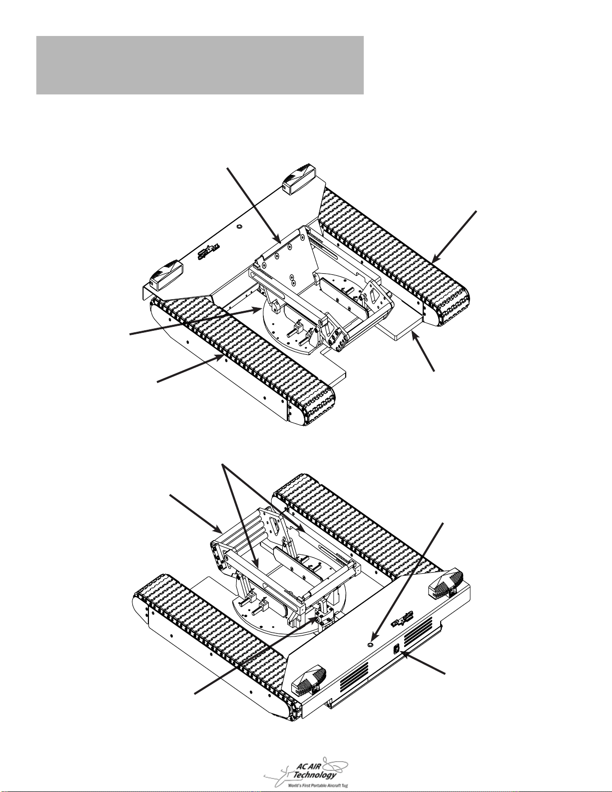
1-2 Tug Components ................................................................................... 4
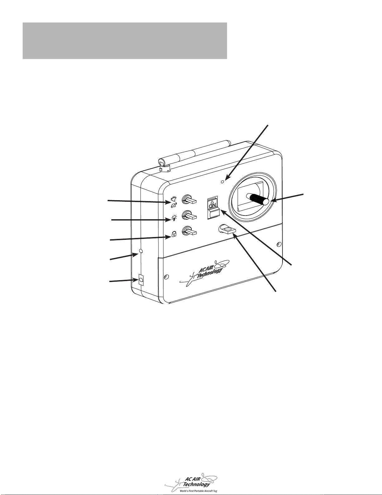
1-3 Remote Control Components ................................................................ 5
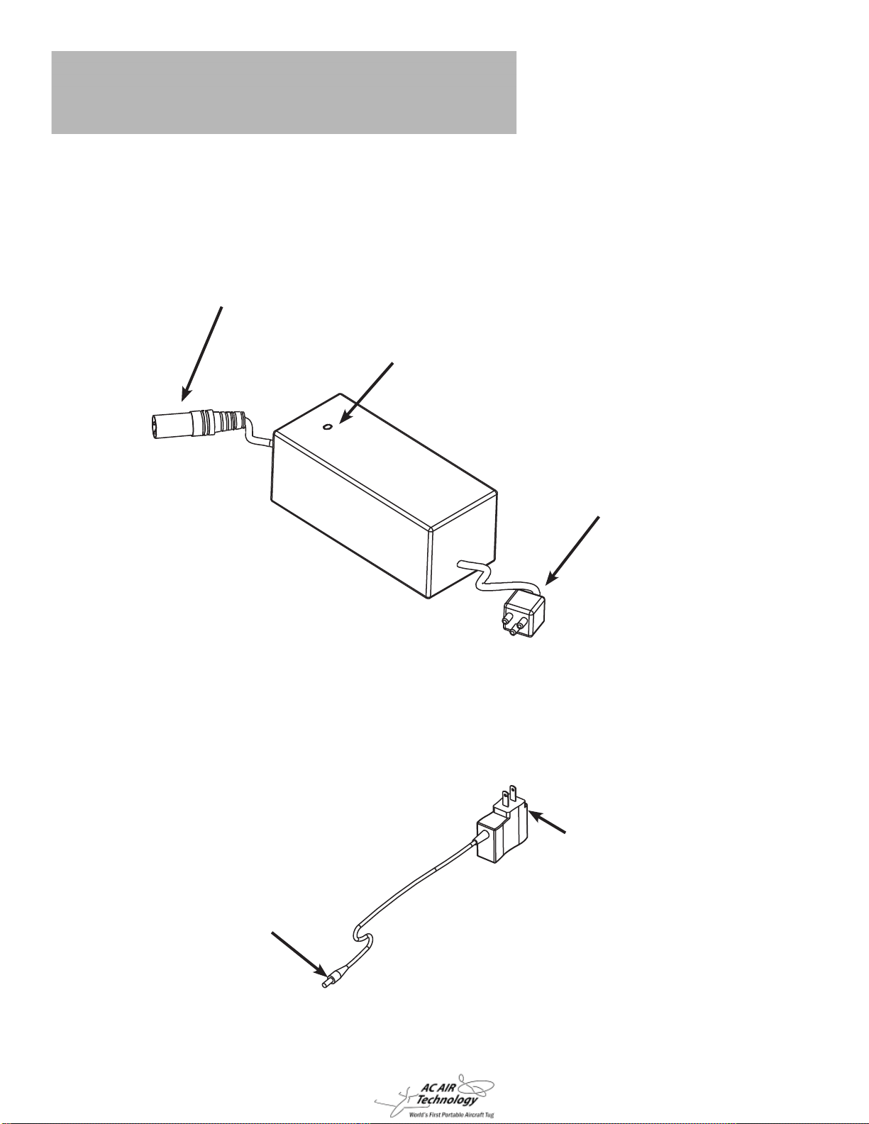
1-4 Charger Components ............................................................................ 6
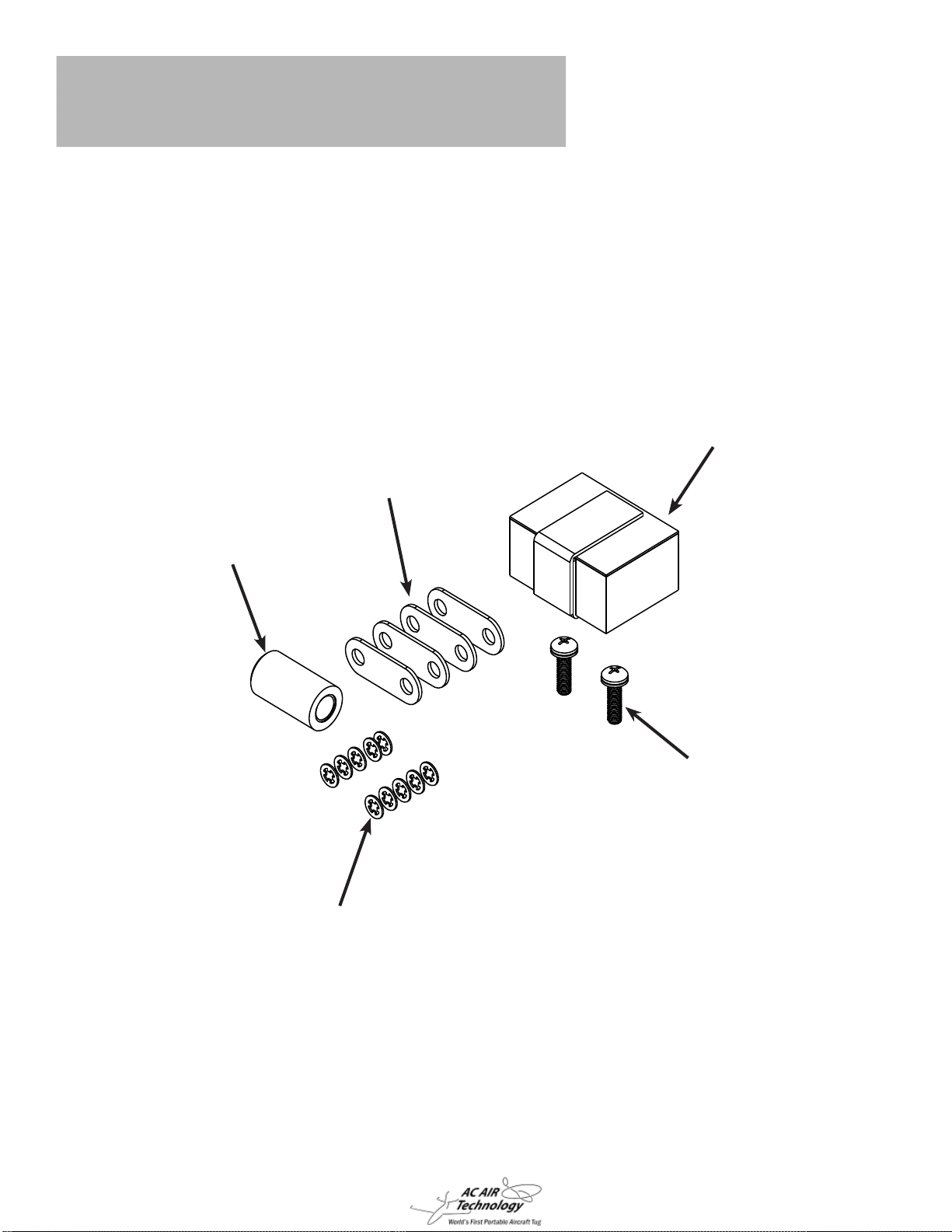
1-5 Spare Parts ........................................................................................... 7
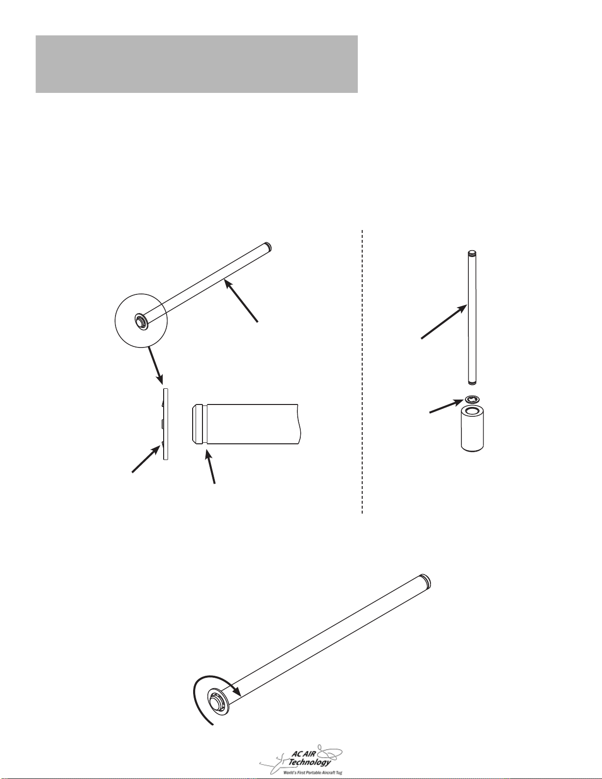
1-6 Track Tools ............................................................................................ 8
1-7 On-Board Parts Box ............................................................................ 10
2. Start-Up Guide .................................................................. 11
2-1 Remote Control Operation .................................................................. 11
2-2 Operating the Tug ................................................................................ 12
2-3 Loading the Aircraft Wheel .................................................................. 14
2-4 Unloading the Aircraft Wheel ............................................................... 17
2-5 Adjusting the Wheel Cradle ................................................................. 20
2-6 Adjusting the Tire Guide Spacers ........................................................ 22
2-7 Adjusting Track Tension ....................................................................... 24
2-8 Lifting the Wheel Cradle Ramp ........................................................... 26
2-9 Charging the Tug ................................................................................. 28
2-10 Charging the Remote Controller ........................................................ 29
2-11 Replacing the Remote Control Batteries ........................................... 30
3. Troubleshooting ...............................................................32
4. Warranty ............................................................................37

3
1-1 Components in the Box
1. Components
Radio Transmitter Battery Tray Radio Charger
Tug Charger Owners Manual Spare Parts Bag
Tug
Track Adjustment Tools Rail Removal Bit

4
1-2 Tug Components
1. Components
Rear Cradle Gate
Lazy Susan
Right Track Assembly
Left Track Assembly Main Plate
Wheel Ramp
Power Switch
Tug Charger Connection
Wheel Lock
Latch Assembly
Wheel Cradle Links

5
1-3 Remote Control Components
1. Components
Control Stick
Lazy Susan Lock &
Cradle Release Switch
Power Indicator
LED
ON/OFF
Switch
Light Switch
3 Speed Toggle
Charging Jack
Lanyard Anchor
Charging Indicator LED
If the remote controller is not used for a few minutes it will start
beeping as a indicator that it is still in the ON position. This is not
an indicator of a low battery.
The control stick on the remote controller is very sensitive and
will cause the tug to move if it is moved accidentally. Turn OFF
the remote controller when not in use.
Warning:
Note:

6
1-4 Charger Components
1. Components
Tug Charger
Radio Charger
110V Power
Connection
Tug Connection
Charging Indicator
LED
110V Power
Connection
Radio Connection

7
Pins
Spare Track Parts
Links
Retainer Clips
Treads
Track Install Tools Fuses
4 Amp Light Fuse
10 Amp Circuit Board Fuse
Retainer Clip Tool
1. Components
1-5 Spare Parts

8
Track Pin Groove
Track Pin
Retainer Clip
Teeth Facing
Outward
Track Pin
Retainer Clip
(Teeth Pointing Down)
1-6 Track Tools
1. Components
The track tools are used to assist in the installation of new tracks.
This section is intended to show how the tools are used only. A detailed instruction
guide is provided when purchasing new tracks. Refer to that instruction guide when
installing new tracks.
When the retainer clip is properly installed into the track pin groove is should rotate
freely inside of the groove.

9
The Track Pin Tools are used to assist in the installation of new tracks when the
they are too tight making it diffi cult to align the pin holes.
Insert the track pin tools on the inside and outside adjacent pins to the missing pin
hole. You will need to hold these in place by hand.
Adjacent Pin
Adjacent Pin
Missing Pin Hole
Track Pin Tools

10
1-7 On-Board Parts Box
1. Components
Rotoclip Install Tool
Track Links / Shims
Parts Box
Rotoclips
Shim Mounting Screws
The On-Board Parts Box contains spare track links / shims, rotoclips, and a rotoclip
tool to quickly replace or repair tracks. It also includes cradle shim mounting screws to
lift the wheel cradle ramp away from the ground. When the ground is very uneven the
wheel cradle ramp may hit the ground preventing the aircraft from loading. These com-
ponents are located on-board the tug, underneath the electronics cover.

11
2-1 Remote Control Operation
2. Start-Up Guide
Reverse
Right Forward
Left
ON/OFF
Power Switch
Lazy Susan Lock &
Cradle Release Switch
Unlock
- Lock
Release
3 Position
Speed Toggle
Fast
- Moderate
Slow
Forward
Right
Reverse
Left
ON
1. Switch the remote control ON. The power indicator light turns on and the remote
control beeps once. If this does not happen, check the remote control battery con-
nection for proper installation. When the battery level is low, the remote control will
begin to beep repeatedly, signaling to replace or recharge the batteries.
2. To drive the tug, move the control stick in the desired direction.
3. The Lazy Susan Lock & Cradle Release Switch is a 3 position switch. The Unlock
and Lock positions are used to lock the lazy susan rotation. The Release position is
to release the tire from the cradle while unloading.

12
2-2 Operating the Tug
2. Start-Up Guide
ON/OFF Switch
1. Before turning on the tug, make sure the tracks and bottom of the tug are free from
obstruction.
2. Turn the tug on using the ON/OFF switch. There will be a short series of beeps
and then the ON/OFF switch will illuminate red to show the tug is on. The ON/OFF
switch light will be on solid when the battery is fully charged. When the tug battery is
low the ON/OFF switch light will blink and there will also be a beeping sound.
3. Turn on the power switch on the radio controller. The power indicator LED will illumi-
nate green/blue in color.
It is recommended you practice maneuvering the tug prior
to loading the plane.
4. It is recommended to use the radio in fast speed mode. Moderate and Slow speed
mode should be used when maneuvering in tight quarters as it reduces the tugs
power output.
5. When towing your airplane ALWAYS be cautious of the steering angle limitations of
your aircraft. Do not over steer your aircraft with the tug. This can cause damage to
your gear.

13
Check sprockets for proper seating and alignment.
6. After lifting the tug off of the ground for any reason or taking it in and out of your air-
craft, you must check the sprockets for proper seating along the tracks. If the sprock-
et is not properly seated it could result in damage to the track.
7. Visually check tracks for wear on the treads and wear on the inner plastic surfaces.
Also inspect for damaged or missing retainer clips as a result of driving over small
rocks. Damaged treads should be replaced before operating the tug.

14
2-3 Loading the Aircraft Wheel
2. Start-Up Guide
Wheel Ramp
in up position,
facing forward
Rotate Lazy
Susan
WARNING:
DO NOT PUT ANY PART OF YOUR BODY IN THE MECHANISM WHILE
RELEASING THE LATCH. SEVERE BODILY INJURY CAN OCCUR.
1. Once the pre-load setup is complete turn ON the tug power switch and remote
controller power switch. The wheel ramp needs to be in the down position before
loading the aircraft wheel. If the wheel ramp is in the up position then hold the latch
release switch on the radio controller and slowly rotate the lazy susan with the con-
troller until the latch releases the ramp and it falls to the down position. The ramp
release only occurs when the lazy susan is oriented with the wheel ramp facing
forward. Once the wheel ramp is in the down position toggle the latch release switch
to the middle position, locking the lazy susan from rotating.
WARNING:
DO NOT SIT IN THE PLANE WHILE DRIVING THE TUG.
TO PREVENT GOING BEYOND YOUR STEERING LIMITS IT IS HIGHLY
RECOMMENDED THAT YOU LOCK THE LAZY SUSAN FROM
ROTATING WHILE GOING UP AND DOWN HILLS AND MOVING
ALONG A STRAIGHT PATH. THE LAZY SUSAN FEATURE SHOULD ONLY BE
USED ON FLAT GROUND AND WHEN MANEUVERING IN TIGHT QUARTERS.

15
Aircraft Tire
Wheel Ramp in
down position,
Lazy Susan
Aircraft Tire
2. Drive the tug to line up the aircraft tire with the center of the wheel ramp.
It may be necessary to apply a little pressure with your foot to
the top of the battery cover to get the wheel started onto the tug.
3. Drive the tug under the aircraft tire until the tire is positioned on top of the lazy
susan. It may be necessary to chock the wheels to keep the plane from moving.

16
Rear Gate
Locked into
Latch Wheel Ramp in
Up Position
Circuit Breaker
4. Continue driving the tug under the tire until the rear gate locks onto the latch and the
wheel ramp is in the up position.
5. The Lazy Susan Lock switch on the radio can be moved to the unlocked position
during operation to allow 360° of rotation.
6. The circuit breaker reset buttons will trip if the tug is overloaded. To reset the circuit
breakers open the access cover and locate the two white or black buttons on the
circuit board. See image above. Press them down to reset the circuit breakers.
Critical Note:
If the circuit breaker buttons pop up after being reset, the tug is being overstressed
and could cause damage to the circuit board. Address any mechanical issues such
as a seized sprocket or missing track retainer clips or any driving conditions such as
driving up a steep incline or towing above the tugs capacity that could be causing
the tug to overstress. If the issue persists call or e-mail AC Air Technology tech sup-
port for further assistance.

17
2-4 Unloading the Aircraft Wheel
2. Start-Up Guide
Push tug slightly
in this direction
Tire puts slight
pressure on rear
gate Wheel Ramp
Facing Front
1. Toggle the Lazy Susan Lock Switch in the middle position and rotate the tug under
the aircraft tire until the wheel ramp is facing the front of the tug. Push the tug so the
rear gate is slightly pushing against the tire.
Note: It is recommended to chock the wheels to keep the plane from moving

18
Wheel Ramp in
Down Position
Drive Tug Away
From Tire
2. Hold the latch release switch on the radio controller and slightly rotate the tug under
the tire until the latch releases the rear gate. You will need to visually verify that the
latch is released. This may require rotating the tug back and forth slightly until the
latch releases.
3. When the latch releases, continue holding the latch release switch on the radio con-
troller and then drive the tug away from the tire. The wheel ramp should pivot to the
down position as you move the tug

19
Keep Driving Tug
Away From Tire
Tire Completely
Off of Tug
4. Continue driving the tug away from the tire until the tire is completely off of the tug.
You can stop holding the latch release switch after the tire is off of the tug.

20
2-5 Adjusting the Wheel Cradle
2. Start-Up Guide
Wheel cradle in the down position
1. Make sure that the wheel cradle is down. If needed, use the radio to unlatch the
cradle.
2. Place wheel chocks behind the rear tires of the plane to ensure the plane does not
roll backwards.
3. Drive the tug under the wheel of the plane until the wheel cradle locks in the upright
position.
Table of contents
Other AC Air Technology Industrial Equipment manuals

AC Air Technology
AC Air Technology Small Tire Cradle Option User manual

AC Air Technology
AC Air Technology AC Tracktech T-MINI with Grab Cradle User manual

AC Air Technology
AC Air Technology T2W3 User manual

AC Air Technology
AC Air Technology T2W2 Aircraft Tug User manual

AC Air Technology
AC Air Technology T1 User manual
Popular Industrial Equipment manuals by other brands

IMI SENSORS
IMI SENSORS PCB Piezotronics M080A130 Installation and operating manual

FRIEDHELM LOH
FRIEDHELM LOH Rittal SK 3363 Series Assembly and operating instructions

SUNFLOWER TRIMMER
SUNFLOWER TRIMMER SORTER USER MANUAL and WARRANTY FORM

HYDROLAB
HYDROLAB HLP Series user manual

FCS
FCS MM Series user manual

Jäger
Jäger F100-H536.11 S3W2 manual