AC Air Technology T1H2 User manual

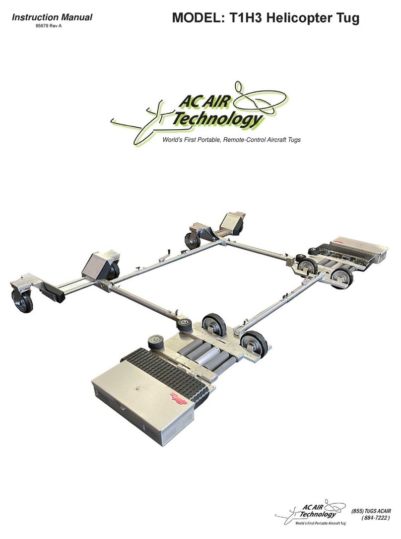
Instruction Manual MODEL: T1H2 Helicopter Tug
World’s First Portable, Remote-Control Aircraft Tugs
95631 Rev. c

2
Contents
1. Components ............................................................................... 3
1-1. Components in the Box (1).....................................................3
1-2. Components in the Box (2).....................................................4
1-3. Components in the Box (3).....................................................5
1-4. Components in the Box (4).....................................................6
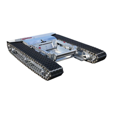
1-5. Tug Components (1)...............................................................7
1-6. Tug Components (2) .............................................................8
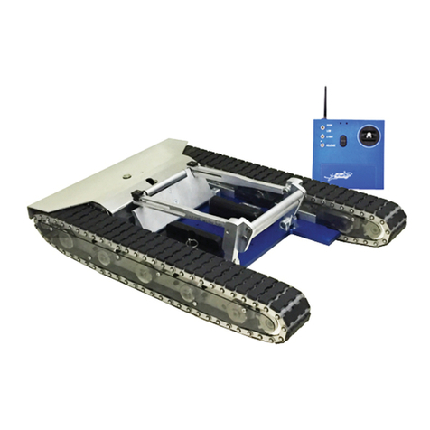
1-7. Radio Components.................................................................9
1-8. Charger Components...........................................................10
1-9. Spare Parts Kit ..................................................................... 11
1-10. Spare Parts: Track Tools ....................................................12
2. Quick Guide ............................................................................. 14
2-1. Air Bag..................................................................................14
2-2. Auxiliary Wheels and Lifter Pole...........................................15
3. Tug Assembly .......................................................................... 16
3-1 Front End Assembly ..............................................................16
3-2 Back End Assembly ..............................................................22
4. Tug Operation .......................................................................... 27
4-1. Radio Operation ...................................................................27
4-2. Operating the Tug.................................................................28
4-3. Adjusting the Width of the T1H2 Tug....................................30
4-4. Loading the T1H2 Under the Helicopter Skids.....................31
4-5. Moving the helicopter with the T1H2 tug..............................37
4-6. Unloading the helicopter from the T1H2 tug.........................38
5. Tug Care ................................................................................... 39
5-1. Adjusting the Track Tension..................................................39
5-2. Charging the Tug..................................................................41
5-3. Charging the Transmitter......................................................42
5-4. Replacing Radio Batteries....................................................43
6. Troubleshooting ...................................................................... 45
7. Warranty ................................................................................... 49

3
1. Components
1-1. Components in the Box (1)
Right Main Tug
Assm. 09612
Left Main Tug
Assm. 09994

4
1-2. Components in the Box (2)
Left End Assembly
Assm. #09889
Right End Assembly
Assm. #09993
Short Front-end Adjuster
Assm. #09621
Long Back-end Adjuster
Assm. #09622
(2X) Frame Side Support
Part #02617

5
1-3. Components in the Box (3)
Auxiliary Wheels
Assm. #02532
Lifter Pole
Assm. #02533
Air Bag
Part #95623
Hand Pump and Hose
Assm. #02532

6
1-4. Components in the Box (4)
Radio Transmitter
Part #02629
Battery Tray
Part #95087
Radio Charger
Part #95102
(2X) Tug Charger
Part #95394
Owners Manual
Part #95631
(2X) Spare Parts Bag
Part #95631
(4X) T-Handle
Part #95545
(4X) T1H2 Frame Insert
Part #24244
(12X) Socket Head
Part #95304
(2X) Shoulder Bolt
Part #95655

7
1-5. Tug Components (1)
Track Assembly
Main Plate
Skid Loading Rollers
Skid Guide Rollers
Tug Charger Connection
Power Switch
Right Back-end Connection Slot
Side to Side Swivel Connection
*Note Left Main Tug is an Identical Mirrored Component

8
Left Main Tug Swivel Connection
Right Main Tug Swivel Connection
1-6. Tug Components (2)
Left Back-End Insert
Right Back-End Insert
Left Back-End Insert Hole
Right Back-End Side to Side Insert
Right Back-End Connection Slot

9
1-7. Radio Components
Warning: The control stick on the remote is very sensitive and will cause
the tug to move if it is moved accidentally. When not using the
remote it is recommended that the power switch is turned OFF.
Note: If the remote is not used for more than a couple minutes it will start
beeping as a indicator that it is still in the ON position. This is not an
indicator of a low battery.
Radio Controller
Control Stick
Power Indicator
LED
ON/OFF
Switch
Light Switch
3 Speed Toggle
Charging Jack
Lanyard Anchor
Charging Indicator LED
(Optional)
Roller Engagement Switch

10
1-8. Charger Components
Tug Charger (2 Included)
Radio Charger
110 V Power
Connection
Tug Connection
Charging Indicator
LED
110 V Power
Connection
Radio Connection

11
1-9. Spare Parts Kit
44
• Spare Track Parts
Pins
Rotoclips
Treads
Links
Retainer Clip Tool
Track Pin Tools
4 Amp Replacement Light Fuse
• Track Install Tools • Spare Track Parts

12
Track Pin
Track Pin Groove
Rotoclip Teeth
Facing Outward
When Rotoclip is properly installed in the track pin groove it should rotate
freely inside of the groove.
Retainer Clip Tool
Rotoclip
(Teeth Pointing Down)
Track Pin
The Track Tools are used to assist in the installation of new tracks.
This section is intended to show how the tools are used only.
A detailed instruction guide is provided when purchasing new tracks.
Refer to that instruction guide when installing new tracks.
1-10. Spare Parts: Track Tools

13
The Track Pin Tools are used to assist in the installation of new tracks
Insert the Track Pin Tools on the inside and outside adjacent pins to
the missing pin hole. Note: You will need to hold these in place by hand.

14
2. Quick Guide
2-1. Air Bag
2 1
34
Hand Pump
Hose
Air Bag
Infl ate the Air Bag to 50-60% capacity
Place the Air Bag centered underneath
the tail of the helicopter as shown
As the tug approaches the helicopter’s
center of gravity the tail will pivot down
and rest on the air bag, protecting the
tail from hitting the ground

15
2-2. Aux. Wheels and Lifter Pole
2 1
34
Rotate the pole to lift the track off the
ground and install the fi rst auxiliary
wheel. There are 4 mating holes on the
main plate, 2 per wheel. They are locat-
ed at each end of the track.
On the opposite end of the track, po-
sition the Lifer Pole underneath the
main plate. Install the second auxiliary
wheel.
Lifer Pole
Auxiliary Wheels
If one track loses power, the auxiliary
wheels can be installed to temporarily
get the failed track off the ground and
the helicopter off of the tug.
Main Plate
At one end of the track, position the Lifer
Pole underneath the tug main plate.
Aux. Wheel
Aux. Wheel

16
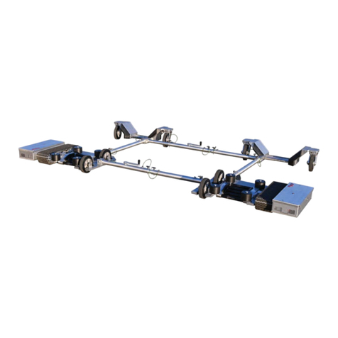
3-1 Front End Assembly
T-Handle Pin
T1H2 Short Adjuster Right End T1H2 Short Adjuster Left End
(2X) 3/8”-16 Shoulder Blot
Right Tug
Left Tug
Measured Helicopter Skid Center to Center Distance
(1)
(2)
(4)
(3)
Center Numbered Tube Insert
End Numbered Tube Insert
(5)
Center Tube
(6)
Adj. Handle
*NOTE*
BEFORE STARTING ASSEMBLY PROCESS PLACE BOTH RIGHT AND LEFT
TUGS APART ABOUT 5 INCHES LESS THAN THE SKID WIDTH MEASURED
EARLIER. IT IS POSSIBLE BOTH TUGS CANNOT BE PLACED 5 INCHES LESS
WITHOUT INTERFERING AND IN THIS CASE THE TUG WIDTH WILL BE AT ITS
MOST MINIMUM.
Assembly Figure 1
3. Tug Assembly

17
2. Insert larger diameter end of Helicopter Frame Insert (Part #24244) into the end of the tube
of assembly #09621. Align the thru holes on both the helicopter frame insert and end of the
tube shown and insert T-Handle pin (Part #95545) far enough until the handle cannot slide
out freely.
1. Slide the smaller diameter end of the Helicopter Frame Insert (Part #24244) into swivel con-
nection shown above. Align the non threaded thru holes and while holding the insert in place
screw in Shoulder Bolt (Part #95655).

18
4. Align the center numbered #1 thru hole and one end of the center tube shown and insert the
T-Handle pin (Part #95545) far enough until the handle cannot slide out freely. Remove the
T-Handle Pin on the side with the adjustment handle and leave out until the tug’s width has
been adjusted to the previously measured width. This connection does not adjust and will re-
main intact when adjusting the width of the T1H2 tug. Facing down on the adjustment handle
turn it counter-clockwise until it can no longer turn.
3. Align the thru holes on both the center numbered tube and end of the tube shown and insert
T-Handle pin (Part #95545) far enough until the handle cannot slide out freely. Take note this
pin will be removed and adjusted in step 6 of this process when connecting both the right and
left tugs.
#1 Thru Hole
Figure 1 Figure 2 Figure 3
Center Tube

19
6. With both tugs placed 5 inches less than the width measured, assuming it is possible and
not at its minimum width, power one of the tugs on to aid in aligning the tubes. Align the
center tube and the end numbered tube insert so they are concentric with one another. Re-
move the T-Handle pin from step three and looking down on the adjustment handle rotate it
clockwise guiding the tube to the desired length. Once the desired length has been achieved
insert the T-Handle pin to connect both the center tube and end numbered tube together
Center Tube
End Numbered Tube
T-Handle Pin (Step 3)
5. Slide the smaller diameter end of the end numbered tube insert into the swivel connection
shown above. Align the non threaded thru holes and while holding the insert in place screw
in Shoulder Bolt (Part #95655).

20
7. Both the right and left tugs are now connected together. Take note of the numbers the T-
Handle Pins have been inserted to after adjustment is complete as shown in the fi gure below.
These numbers will aide with the back end assembly width adjustment in the fi nal step.
Measured Helicopter Skid Center to Center Distance
Mid Section Tube Number
End Tube Number
Table of contents
Other AC Air Technology Utility Vehicle manuals