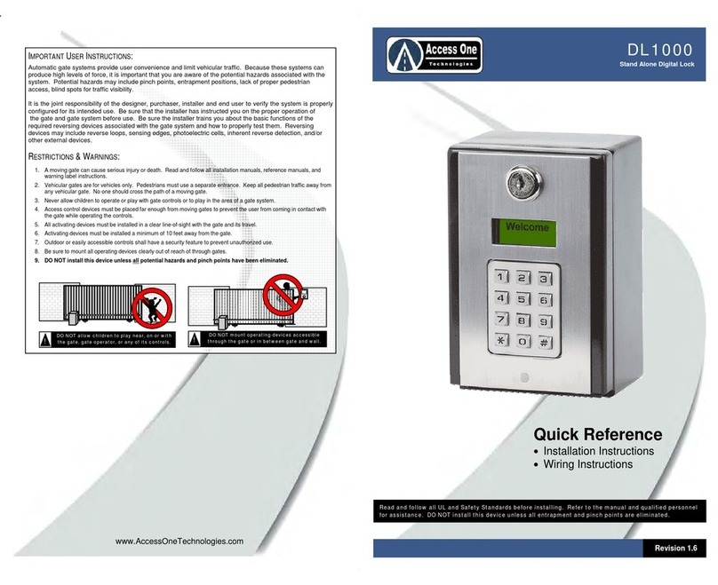
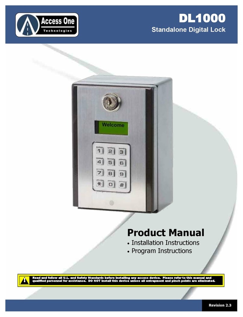
Access One DL1000 User manual

Read and follow all U.L. and Safety Standards before installing any access device. Please refer to this manual and
qualified personnel for assistance. DO NOT install this device unless all entrapment and pinch points are eliminated.
!
1
Revision 1.6A
DL1000
Standalone Digital Lock
Product Manual
Installation Instructions
Program Instructions

DL1000
Product Manual
DL1000, Rev 1.6A Page 2
Important Safety Information
Important User Instructions ................................. 3
Restrictions & Warnings ..................................... 3
Installation
Mounting The System ......................................... 4
Grounding The System ....................................... 4
Powering The System ......................................... 4
Basic Wiring Overview ........................................ 4
Gate Operator Wire Connections ........................ 4
Electric Strike Wire Connections ......................... 4
Magnetic Lock Wire Connections ....................... 4
Event Input Wire Connections ............................ 5
Auxiliary Open Wire Connections ....................... 5
Programming
System Status ..................................................... 6
Program Access Code (PAC) ............................. 6
Time Clock Programming .................................... 6
Add Simple Entry Codes ..................................... 6
Add Single Customized Codes ........................... 7
Delete Single Entry Codes .................................. 8
Add Simple Block Entry Codes ........................... 8
Add Block Customized Codes ............................ 8
Delete Block Entry Codes ................................... 9
Auxiliary Input Programming ............................... 9
Entry Code Length Programming ....................... 9
Relay Activation Time Programming ................... 10
System Reset ..................................................... 10
Strikes Lockout Programming ............................. 10
Sleep Mode Programming .................................. 10
Relay Time Schedule Programming.................... 11
Delete Relay Time Schedules ............................. 11
Operating Instructions
Using Entry Codes .............................................. 12
Entry Codes With Time Schedules...................... 12
Entry Codes With Sleep Mode ............................ 12
System Status & Clock ....................................... 12
Do Not Disturb (DND) Feature ............................ 12
Glossary ............................................................. 12
User Safety Guidelines........................................ 12
Troubleshooting
Troubleshooting Chart ........................................ 13
Limited Warranty
Limited Warranty ................................................ 14
CONTENTS

DL1000
Product Manual
DL1000, Rev 1.6A Page 3
SAFETY INFORMATION
Important User Information:
Automatic gate systems provide user convenience and limit
vehicular traffic. Because these systems can produce high levels
of force, it is important that you are aware of the potential
hazards associated with the system. Potential hazards may
include pinch points, entrapment positions, lack of proper
pedestrian access, blind spots for traffic visibility.
It is the joint responsibility of the designer, purchaser, installer
and end user to verify the system is properly configured for its
intended use. Be sure the installer has instructed you on the
proper operation of the gate system before use. Be sure the
installer trains you about the basic functions of the required
reversing devices associated with the gate system and how to
properly test them. Reversing devices may include reverse loops,
sensing edges, photoelectric cells, inherent reverse detection,
and/or other external devices.
WARNING - To reduce the risk of injury or death:
1. A moving gate can cause serious injury or death. Read and follow
all installation manuals, reference manuals, and warning label
instructions.
2. Vehicular gates are for vehicles only. Pedestrians must use a
separate entrance. Keep all pedestrian traffic away from any
vehicular gate. No one should cross the path of a moving gate.
3. Never allow children to operate or play with gate controls. Never
allow children to play in the area of a gate system.
4. Access control devices must be placed far enough from moving
gates to prevent the user from coming in contact with the gate
while operating the controls.
5. All activating devices must be installed in a clear line-of-sight with
the gate and its travel.
6. Activating devices must be installed a minimum of 10 feet away
from the gate.
7. Outdoor or easily accessible controls shall have a security feature
to prevent unauthorized use.
8. Mount all operating devices clearly out of reach of through gates.
9. DO NOT install this device unless all potential hazards and
pinch points have been eliminated.
INSTALLATION
Mounting The System:
The system can be mounted on a standard pedestal or
directly to a wall or flat surface. A 1/2” knockout is located
on the back of the box for conduit connections. A 3” x 3”
hole pattern is available for mounting screws and anchors.
Follow all safety warnings and precautions when mounting
the system.
Pedestal Mounting:
1. Use security screws and lock nuts to securely attach the back
box to a gooseneck post.
2. If the mounting holes are not used, fill the holes with a plug
or sealant to prevent water from entering the box.
Wall Mounting:
1. Mount the system to a wall or flat surface. Use appropriate
mounting screws or anchors to securely attach the system.
2. Never mount the system to a moving gate, gate panel, or
next to a gate that causes vibration to the mounting point.
Continuous vibration from moving or slamming gates can
cause damage to the unit and is not covered under warranty.
Grounding The System:
It is important to properly ground the system. An improper
ground or static electricity may damage the system and is not
covered under warranty. To properly ground the system:
1. Always try to discharge any static electricity before handling
the PCB.
2. Attach a 12 AWG ground wire from the green ground wire on
the circuit board.
3. Run the ground wire to a good ground point within 12 feet.
Mounting posts set in concrete are not a sufficient ground.
Good grounds include 10 foot grounding rods, grounded
metal conduits, and grounds at an electric panel.
4. In areas prone to lighting or power fluctuations, additional
protection such as surge suppressor are recommended.
DO NOT allow children to play near, on or with
the gate, gate operator, or any of its controls.
!
DO NOT mount operating devices accessible
through the gate or in between gate and wall.
!
Mount the system at least 10 feet away from
a vehicular gate and its travel.
!
3”
3”
4”
3”
3”

DL1000
Product Manual
DL1000, Rev 1.6A Page 4
INSTALLATION
Powering The System:
Always use a good solid power source. To properly power the
system:
1. Provide power from a dedicated
power source for best results and
to prevent power fluctuations.
2. Use the following chart for
proper wire size and distance to
the system. Use U.L. listed wire
with an insulation rating of 600
volts. When installed outdoors,
use direct underground burial
wire inside a conduit for best
results.
3. Connect a 12-24VAC/VDC power source to the power
terminals located on the right middle side of the circuit board.
Basic Wiring Overview:
The DL1000 has two relays to control several types of devices. To
connect the DL1000 for basic use:
1. Connect a 12-24VAC/VDC power source to the Power
Terminal.
2. Connect the activation device to the Relay 1 or Relay 2 inputs.
There are NO, NC, and C inputs.
3. Connect bypass devices such as Postal Locks to the Exit 1 or
Exit 2 inputs.
4. Connect Event devices such as loop detectors, wireless
detectors to the Event input for controlled access.
INSTALLATION
Gate Operator Wire Connection:
The system may be connected to an electric gate operator for gate
access control. When connecting to an electric gate operator,
always follow the safety guidelines and precautions supplied with
the gate operator. To connect the system to a gate operator:
1. Connect NO1 to Gate Open Input.
2. Connect COM1 to Gate Common.
3. Use at least 18AWG or larger wire.
4. Important: Follow all safety guidelines and precautions when using
the system with an automatic gate operator.
Electric Strike Wire Connections:
The system may be connected to an electric strike for pedestrian
door or pedestrian gate control. To connect the system to an
electric strike:
1. Connect NO1 to the Strike power source.
2. Connect the Strike power source to the Electric Strike.
3. Connect COM1 directly to the Strike.
4. Use at least 18AWG or larger wire.
5. Important: A separate power source must be wired in series with the
system and the Electric Strike. Do not use the system supplied
transformer to power the Electric Strike.
Magnetic Lock Wire Connections:
The system may be connected to an magnetic lock for pedestrian
door or pedestrian gate control. To connect the system to a
magnetic lock:
1. Connect NC1 to the Magnetic Lock power source.
2. Connect the Magnetic Lock power source to the Magnetic Lock.
3. Connect COM1 directly to the Magnetic Lock.
4. Use at least 18AWG or larger wire.
5. Important: A separate power source must be wired in series with the
system and the Magnetic Lock. Do not use the system supplied
transformer to power the Magnetic Lock.
Wire Size Distance
18 AWG 75 Feet
16 AWG 150 Feet
14 AWG 250 Feet
12 AWG 500 Feet
Mag Lock
Power
Electric
Strike
Power
1 2 3 4 5
12-24 AC/DC
C Ev Ex1 Ex2
1 2 3 4 5
1 2 3 4 5
Electric
Strike
Power
1 2 3 4 5
Mag Lock
Power

DL1000
Product Manual
DL1000, Rev 1.6A Page 5
INSTALLATION
Event Input Wire Connections:
The Event Input allows an external device such as a loop detector
to control set entry codes when the external device is active. An
entry code set to use the Event Input must route through this
input before activation.
Loop Detector Example:
If a loop detector is used, a car must be over the loop giving a
closure for the code to be valid. This is an important feature to
help prevent pedestrians from using a vehicular gate for access.
To connect the external device (loop detector) to the system:
1. Connect COM to the external device or Loop Detector
2. Connect EVENT to the external device or Loop Detector
INSTALLATION
Auxiliary Open Wire Connections:
Auxiliary devices such as Free Exit Boxes, Fire Lock Boxes, or Key
Lock Boxes may be connected to the system to operate Relay 1 or
Relay 2. Devices connected to these inputs will override the
system settings and allow for immediate control. To connect to
the Auxiliary Override inputs:
To activate Relay 1:
1. Connect COM to the open device.
2. Connect EXIT 1 to the open device.
To activate Relay 2:
1. Connect COM to the open device.
2. Connect EXIT 2 to the open device.
Caution:
Gate controls must be placed far enough from the gate to prevent the
user from coming in contact with the gate while operating the controls.
All activating devices must be installed in a clear line-of-sight with the
gate and its travel.
Activating devices must be installed a minimum of 10 feet from the gate
and its travel.
Be sure to mount ALL operating devices clearly out of reach of through
gates. Do not mount the system between the gate and wall.
Controls intended to be used to reset an operator after two sequential
activations of the entrapment protection must be located in a line-of-
sight of the gate. Outdoor or easily accessible controls shall have a
security feature to prevent unauthorized use.
1 2 3 4 5
C Ev Ex1
Ex2
DO NOT allow pedestrian use of a vehicular gate.
No one should cross the path of a moving gate!
!
DO NOT mount operating devices accessible
through the gate or in between the gate and wall.
!
1 2 3 4 5
C Ev Ex1
Ex2

DL1000
Product Manual
DL1000, Rev 1.6A Page 6
PROGRAMMING
System Status:
The current system status may be viewed at any time. The
system status displays the current status of Relay 1, Relay 2, Do
Not Disturb, and the clock time and date.
To view the system status (Relay & DND):
1. Press and hold for 3 seconds (STATUS)
2. Press to return to the Welcome screen (WELCOME)
To view the system clock (Time & Date):
1. Press (Displays Clock Date & Time)
2. Press to return to Welcome screen (WELCOME)
Program Access Code (PAC):
The Program Access Code (PAC) is a 6-digit number used to gain
access to the programming mode. The factory setting is “000000”
for each system. To change the PAC:
1. Press and hold for 3 seconds.
2. Enter current PAC (PROGRAM)
3. Enter (USERPREF)
4. Enter (OLD CODE)
5. Enter old PAC (NEWCODE)
6. Enter new PAC (RE-ENTER)
7. Enter new PAC (CHANGED)
8. Press to exit.
The PAC may be reset to the factory default “000000” if the code
is lost or forgotten. To reset the PAC to the factory default:
1. Turn the power off to the system
2. Press and hold while turning the power back on.
For quick reference, record the system’s serial number and PAC:
Serial Number
Program Access Code
PROGRAMMING
Time Clock Programming:
The DL1000 has a built-in 7-Day Plus time clock for time control of
individual codes and relay open schedules. Codes and schedules
can be controlled by time, day, and/or date. The clock is a 12-
hour format. To set the date and time on the clock:
1. Press and hold for 3 seconds
2. Press PAC (PROGRAM)
3. Press for time clock settings
4. Enter date then
5. Enter day of week then (1=SUN)
6. Enter time then (12-hour format)
7. Enter AM/PM then (1=AM, 2=PM)
8. CLOCK SET. Press to exit.
Add Simple Entry Code:
Simple entry codes may be entered to speed up programming.
When a simple code is entered, it will use the default settings
listed below. Codes may be 4-6 digits. To program a simple entry
code:
1. Press and hold for 3 seconds (STATUS)
2. Press PAC (PROGRAM)
3. Press (CODE)
4. Press 4-6 digits (NEW CODE) then
5. Repeat step 4 for more codes.
6. Press to exit.
Note: To edit entry code features, use # for each setting to
accept the default or make the change at each step.
*
*
#
#
*
8 #
3 #
**#
*
*
3 #
m m d d y y #
#
h h m m s s #
#
**#
*
1 #
# 0
** #
*
Settings Default Settings Default
Relay 1 Function Momentary Relay 2 Event Control Off
Relay 1 Event Control Off Relay 2 Time Control Off
Relay 1 Time Control Off Flash Code Uses 99 (Unlimited)
Relay 2 Function None Do Not Disturb No

DL1000
Product Manual
DL1000, Rev 1.6A Page 7
PROGRAMMING
Add Single Customized Code:
When adding a new entry code, press # for each setting to accept
the system defaults. Codes may be 4-6 digits. To customize an
individual entry code, program each step as needed. To program
a customized code:
1. Press and hold for 3 seconds (STATUS)
2. Press PAC (PROGRAM)
3. Press (CODE)
4. Press for code 4-6 digits. (NEW CODE)
5. Press (RELAY 1) or to edit code
6. Press or 1-6 for Relay 1 Function, #=Momentary
7. Press or 1-2 for Relay 1 Event Control, #=Off
8. Press or 1-2 for Relay 1 Time Control, #=Off. If
off, skip to step 16
9. Press or start date, #=Current date
10. Press or end date, #=No end date
11. Press or for active days of week.
#=All days. (Example: 1=Sunday, 246=MWF)
12. Press or for start time. #=12:00:00
Time is 12 hour format.
13. Press for AM/PM setting. (1=AM, 2=PM)
14. Press or for end time. #=12:00:00
Time is 12 hour format.
15. Press for AM/PM setting. (1=AM, 2=PM)
16. Press or 1-6 for Relay 2 Function, #=None
17. Press or 1-2 for Relay 2 Event Control, #=Off
18. Press or 1-2 for Relay 2 Time Control, #=Off. If
Off skip to step 25.
19. Press or start date, #=Current date
20. Press or end date, #=No end date
21. Press or for active days of week.
#=All days. (Example: 1=Sunday, 246=MWF)
PROGRAMMING
Add Single Customized Code (Cont):
21. Press or for start time. #=12:00:00
Time is 12 hour format.
22. Press for AM/PM setting. (1=AM, 2=PM)
23. Press or for end time. #=12:00:00
Time is 12 hour format.
24. Press for AM/PM setting. (1=AM, 2=PM)
25. Press or for Flash Code uses. 00-98 uses,
99=Unlimited, #=99 Unlimited
26. Press or 1-2 for Do Not Disturb setting. #=Off.
1=Off, 2=On
27. Repeat step 4-27 for more codes.
28. Press to exit.
*
1 #
# 1 #
# #
# #
# #
# m m d d y y #
# m m d d y y #
# #
# h h m m s s #
#
# h h m m s s #
#
# #
# #
# #
# m m d d y y #
# m m d d y y #
# #
# h h m m s s #
#
# h h m m s s #
#
# #
# #
**#
Enter Event Control Display
1 Off OFF
2 On ON
# Default = Off OFF
Enter DND Access Display
1 On ON
2 Off OFF
# Default = Off OFF
Enter Relay Action Display
1 None NONE
2 Momentary MOMENT
3 Latch LATCH
4 Latch Timeout LTIMEOUT
5 Unlatch UNLATCH
6 Toggle TOGGLE
7 Toggle Timeout TTIMEOUT
Description
Does not open or close gate
Opens gate, then closes gate
Holds gate open until Unlatch code is used
Holds gate open for xx:xx time
Closes gate
Opens gate, then closes gate on next entry
Holds gate for xx:xx time, then close on
next entry
Settings Default Settings Default
Relay 1 Function Momentary Relay 2 Event Control Off
Relay 1 Event Control Off Relay 2 Time Control Off
Relay 1 Time Control Off Flash Code Uses 99 (Unlimited)
Relay 2 Function None Do Not Disturb No

DL1000
Product Manual
DL1000, Rev 1.6A Page 8
PROGRAMMING
Deleting Single Entry Codes:
To delete a single entry code:
1. Press and hold for 3 seconds (STATUS)
2. Press PAC (PROGRAM)
3. Press (CODE)
4. Press (EXISTS)
5. Press (LOC DEL)
6. Press (CONFIRM)
7. Press (CODE)
8. Repeat step 4-7 for more codes.
9. Press to exit.
Add Simple Block Codes:
A block of simple entry codes may be entered to speed up basic
entry code programming. When a block of simple entry codes are
entered, all codes in the block will use the default settings. Codes
may be 4-6 digits. To customize a block of entry codes using
different settings, refer to “Adding Block Customized Codes.” To
program a block of simple entry codes using default settings:
1. Press and hold for 3 seconds.
2. Enter PAC (PROGRAM)
3. Press (BLOCK)
4. Press (START)
5. Press starting code (4-6 digits)
6. Press ending code (4-6 digits)
7. Press to accept all defaults
8. Repeat step 4-7 for more blocks.
9. Press to exit.
PROGRAMMING
Add Customized Block Codes:
When adding a block of entry code, press # for each setting to
accept the system defaults. Codes may be 4-6 digits. To
customize an entry code settings, program each step as needed.
To program a customized block of codes:
1. Press and hold for 3 seconds (STATUS)
2. Press PAC (PROGRAM)
3. Press (CODE)
4. Press (START)
5. Press starting code (4-6 digits)
6. Press ending code (4-6 digits)
7. Press (RELAY 1) or to edit code
8. Press or 1-6 for Relay 1 Function, #=Momentary
9. Press or 1-2 for Relay 1 Event Control, #=Off
10. Press or 1-2 for Relay 1 Time Control, #=Off. If
off, skip to step 16
11. Press or for start date, #=Current
date
12. Press or for end date, #=No end date
11. Press or for active days of week.
#=All days. (Example: 1=Sunday, 246=MWF)
12. Press or for start time. #=12:00:00
Time is 12 hour format.
13. Press for AM/PM setting. (1=AM, 2=PM)
14. Press or for end time. #=12:00:00
Time is 12 hour format.
15. Press for AM/PM setting. (1=AM, 2=PM)
16. Press or 1-6 for Relay 2 Function, #=None
17. Press or 1-2 for Relay 2 Event Control, #=Off
18. Press or 1-2 for Relay 2 Time Control, #=Off. If
Off skip to step 25.
19. Press or for start date, #=Current date
*
1 #
2
#
#
**#
*
2 #
1 #
0 *
**#
*
2 #
1 #
# 1 #
# #
# #
# #
# m m d d y y #
# m m d d y y #
# #
# h h m m s s #
#
# h h m m s s #
#
# #
# #
# #
# m m d d y y #
Settings Default Settings Default
Relay 1 Function Momentary Relay 2 Event Control Off
Relay 1 Event Control Off Relay 2 Time Control Off
Relay 1 Time Control Off Flash Code Uses 99 (Unlimited)
Relay 2 Function None Do Not Disturb No

DL1000
Product Manual
DL1000, Rev 1.6A Page 9
PROGRAMMING
Add Customized Block Codes (Cont):
20. Press or for end date, #=No end date
21. Press or for active days of week.
#=All days. (Example: 1=Sunday, 246=MWF)
22. Press or for start time. #=12:00:00
Time is 12 hour format.
23. Press for AM/PM setting. (1=AM, 2=PM)
24. Press or for end time. #=12:00:00
Time is 12 hour format.
25. Press for AM/PM setting. (1=AM, 2=PM)
26. Press or for Flash Code uses. 00-98 uses,
99=Unlimited, #=99 Unlimited
27. Press or 1-2 for Do Not Disturb setting. #=Off.
1=Off, 2=On
28. Repeat step 4-28 for more codes.
29. Press to exit.
Delete Block Codes:
Entry codes may be deleted individually or as a block. To delete a
block of entry codes:
1. Press and hold for 3 seconds.
2. Press PAC (PROGRAM)
3. Press (BLOCK)
4. Press (START)
5. Press starting code (4-6 digits)
6. Press ending code (4-6 digits)
7. Press to confirm
8. Repeat step 4-7 for more blocks.
9. Press to exit.
PROGRAMMING
Auxiliary Input Programming:
This programming will set the Relay Functions, Event Control, and
Do Not Disturb (DND) control of the Auxiliary Inputs. All external
devices (fire boxes, key boxes, pushbuttons) connected to the
Auxiliary Inputs will activate the relays and be controlled to the
setting programmed below:
1. Press and hold for 3 seconds.
2. Press PAC (PROGRAM)
3. Press (RLY OPTS)
4. Press (EXIT1)
5. Press or 1-6 for Relay 1 Function, #=Momentary
6. Press or 1-2 for Relay 1 Event Control, #=Off
7. Press or 1-6 for Relay 2 Function, #=Momentary
8. Press or 1-2 for Relay 2 Event Control, #=Off
9. Press or 1-2 for DND, #=Off.
10. Press to exit.
Entry Code Length Programming:
CAUTION: This program step will clear the entry code memory!
To eliminate problems, determine the entry code length prior to
programming. Entry codes can be 4 to 6 digits in length. The
factory default is 4-digits. To delete a block of entry codes:
1. Press and hold for 3 seconds.
2. Press PAC (PROGRAM)
3. Press (USERPREF)
4. Press (CODE LEN)
5. Press 4-6=Entry code length. 4=default
6. Press to confirm (erases all entry codes)
7. Press to exit.
# m m d d y y #
# #
# h h m m s s #
#
# h h m m s s #
#
# #
# #
**#
*
2 #
3 #
#
**#
*
7 #
1 #
# #
# #
# #
# #
# #
**#
*
8 #
6 #
#
#
**#

DL1000
Product Manual
DL1000, Rev 1.6A Page 10
PROGRAMMING
Relay Activation Time Programming:
The Relay Activation Time sets the amount of time each relay will
be activated when an entry code is entered. The Relay Timeout
Time sets the amount of time each relay will remain active when a
Latch Timeout code or Toggle Timeout code is used. See the
chart below for default times. To change the relay time settings:
1. Press and hold for 3 seconds.
2. Press PAC (PROGRAM)
3. Press (RLY OPTS)
4. Press (R TIMES)
5. Press or for time, then for seconds/minutes
(1=seconds, 2=minutes. #=1 second) Relay 1 Activation
6. Press or for time, then for seconds/minutes
(1=seconds, 2=minutes. #=1 second) Relay 1 Timeout Time
7. Press or for time, then for seconds/minutes
(1=seconds, 2=minutes. #=1 second) Relay 2 Activation
8. Press or for time, then for seconds/minutes
(1=seconds, 2=minutes. #=1 second) Relay 2 Timeout Time
9. Press to exit.
System Reset:
CAUTION: This step will clear the system memory including all
entry codes and relay functions. To clear the entire system and
reset the unit:
1. Press and hold for 3 seconds.
2. Press PAC (PROGRAM)
3. Press (USERPREF)
4. Press (RESET)
5. Press to confirm. (All codes will be cleared)
6. Press to exit, Turn power off/on to reset.
PROGRAMMING
Strikes Lockout Programming:
Strikes Lockout helps prevent unauthorized users from using
multiple codes to access the system. The system has a 3-minute
lockout feature that is activated when “x” number of invalid entry
codes are entered. The strike count is cleared each time a valid
entry code is entered. Once the system enters the lockout mode,
it may only be reset by waiting the 3-minutes or resetting power.
The default setting is “3” strikes. A setting of “0” will turn the
feature off. To change the lockout count:
1. Press and hold for 3 seconds.
2. Press PAC (PROGRAM)
3. Press (RLY OPTS)
4. Press (LOCKOUT)
5. Press 1-9=Number of strikes, 0=Off (unlimited)
6. Press to exit.
Sleep Mode Programming:
Sleep mode is used to turn the keypad and LCD off 30 seconds
after use to save power. Press any key to wake the system and
turn the keypad and LCD back on. The first key pressed is used to
wake the system. To change the sleep mode settings:
1. Press and hold for 3 seconds.
2. Press PAC (PROGRAM)
3. Press (RLY OPTS)
4. Press (LOCKOUT)
5. Press 1=Off, 2=On, #=Off (Default)
6. Press to exit.
*
7 #
3 #
# #
# #
# #
# #
**#
*
8 #
9 #
#
**#
*
8 #
4 #
#
**#
*
8 #
1 #
#
**#
Relay Setting Default
Relay 1 Activation Time 1 Second
Relay 1 Timeout Time 2 Minutes
Relay 2 Activation Time 1 Minute
Relay 2 Timeout Time 2 Minutes

DL1000
Product Manual
DL1000, Rev 1.6A Page 11
PROGRAMMING
Relay Time Schedule Programming:
Relay Time Schedules may be used to control the gate or door
without the use of an entry code during certain times of the day.
These schedules can be used to open the gate/door, hold the
gate/door open for a programmed time or date, and/or release the
gate/door at a programmed time or date. The LATCH relay action
should be used. To program a Relay Time Schedule:
1. Press and hold for 3 seconds (STATUS)
2. Press PAC (PROGRAM)
3. Press (RLY OPTS)
4. Press (R SCHED)
5. Press 01-99 Schedule numbers
6. Press for new schedule or to edit a schedule
7. Press or 1-6 for Relay 1 Function, #=Momentary
8. Press or 1-2 for Relay 1 Event Control, 1 or #=Off
9. Press or start date, #=Current date
10. Press or end date, #=No end date
11. Press or for active days of week.
#=All days. (Example: 1=Sunday, 246=MWF)
12. Press or for start time. #=12:00:00
Time is 12 hour format.
13. Press for AM/PM setting. (1=AM, 2=PM)
14. Press or for end time. #=12:00:00
Time is 12 hour format.
15. Press for AM/PM setting. (1=AM, 2=PM)
16. Press or 1-6 for Relay 2 Function, #=None
17. Press or 1-2 for Relay 2 Event Control, #=Off
18. Press or start date, #=Current date
20. Press or end date, #=No end date
21. Press or for active days of week.
#=All days. (Example: 1=Sunday, 246=MWF)
PROGRAMMING
Relay Time Schedule Programming (Cont):
21. Press or for start time. #=12:00:00
Time is 12 hour format.
22. Press for AM/PM setting. (1=AM, 2=PM)
23. Press or for end time. #=12:00:00
Time is 12 hour format.
24. Press for AM/PM setting. (1=AM, 2=PM)
25. Press to exit.
Delete Relay Time Schedules:
To delete a Relay Time Schedule:
1. Press and hold for 3 seconds (STATUS)
2. Press PAC (PROGRAM)
3. Press (RLY OPTS)
4. Press (R SCHED)
5. Press 01-99 Schedule number
6. Press (LOC DEL)
7. Press (CONFIRM)
8. Press to exit.
*
7 #
4 #
# # 1
# #
# #
# m m d d y y #
# m m d d y y #
# #
# h h m m s s #
#
# h h m m s s #
#
# #
# #
# m m d d y y #
# m m d d y y #
# #
# h h m m s s #
#
# h h m m s s #
#
**#
*
7 #
4 #
2 #
#
**#
Enter Event Control Display
1 On ON
2 Off OFF
# Default = Off OFF
Enter Relay Action Display
1 None NONE
2 Momentary MOMENT
3 Latch LATCH
4 Latch Timeout LTIMEOUT
5 Unlatch UNLATCH
6 Toggle TOGGLE
7 Toggle Timeout TTIMEOUT

DL1000
Product Manual
DL1000, Rev 1.6A Page 12
OPERATING INSTRUCTIONS
Using Entry Codes:
To use a programmed entry code:
1. Press for the code. Codes can be 4-6 digits.
If the system is set to 4-digit codes, then the code is detected
upon the 4th digit input.
2. Pressing or before or after each entry code is not
required. If a # or * is entered, it is ignored. This makes the
keypad codes compatible with other brands if necessary.
Entry Codes With Time Schedules:
Entry codes and Relay Time Schedules can be used together for
better control of the system. When Latch or Unlatch entry codes
and times schedules are used, the last action is used. For
example:
1. If a hold open time schedule is active (LATCH) and a Unlatch
Entry code is used, the system will unlatch.
2. If a Latch code is active and an Unlatch schedule becomes
active, the system will unlatch.
3. If an Unlatch code is active and a Latch schedule becomes
active, the system will latch.
4. Momentary and Toggle codes are ignored during an active
Relay Time Schedule.
Entry Codes With Sleep Mode:
Sleep Mode turns the LCD and keypad off after 30 seconds. When
a code is used while the system is in sleep mode, a key must be
pressed before the code is seen. The first key input is used to
wake the system and then it looks at each keypad entry. For
example, if the system is in sleep mode and a user enters code
1234, only 234 will be seen by the system as the “1” was used to
wake the system. The user needs to press a button to wake the
system and then enter 1234.
System Status & Clock:
The current system status may be viewed at any time. The
system status displays the current status of Relay 1, Relay 2, Do
Not Disturb, and the clock time and date.
To view the system status (Relay & DND):
1.Press and hold for 3 seconds (STATUS)
2.Press to return to the Welcome screen (WELCOME)
To view the system clock (Time & Date):
1.Press (Displays Clock Date & Time)
2.Press to return to Welcome screen (WELCOME)
OPERATING INSTRUCTIONS
Do Not Disturb (DND) Feature:
The Do Not Disturb (DND) mode puts the system into a sleep
mode and does not allow entry code or relay activation while DND
is On (active). Entry codes that have been programmed with DND
Access = ON will be able to activate the relays when the DND
mode is On (active). The DND can be toggled ACTIVE/INACTIVE
from the program mode. To control the DND mode:
1. Press and hold for 3 seconds (STATUS)
2. Press PAC (PROGRAM)
3. Press (DO NOT DISTURB)
4. Press (R SCHED)
5. Press 1=Active/on, 2=Inactive/off
8. Press to exit.
Glossary:
Entry code:
a code used by an individual to activate or control the
system. When a valid code is entered, the system will activate as
programmed.
Flash code:
a code that can be used xx amount of times. Once the
number of times has been used, the code becomes inactive. Example: a
contractor may be given a code that will open the gate 10 times. On the
11th try, the code will not open the gate.
PAC:
Program Access Code
Program Access Code:
code used to gain access to the programming
mode.
Strikes Lockout:
helps prevent unauthorized users from using multiple
codes to access the system. The system has a 3-minute lockout feature
that is activated when “x” number of invalid entry codes are entered.
User Safety Guidelines:
1. Read and follow all installation manuals and warning instructions.
2. Do not use a vehicular gate for pedestrian access. Vehicular gates
are for vehicles only. Pedestrians must use a separate entrance.
3. Never allow children to operate or play with gate controls. Never
allow children to play in the area of a gate system.
4. Never reach through a gate to use a device.
5. Only use the system when you have a clear line-of-sight with the
gate and its travel.
6. If the unit is not installed correctly or in a safe manner, turn the
unit off immediately and do not use.
7. DO NOT install or use this device unless all potential
hazards and pinch points have been eliminated.
# *
*
*
#
#
*
4 #
4 #
#
**#

DL1000
Product Manual
DL1000, Rev 1.6A Page 13
SYMPTOM: POSSIBLE SOLUTION:
System does not appear to have power 1. Check to make sure the supplied transformer is plugged in.
2. Check the connections to the supplied transformer for clean tight connections.
3. Check the connections to the system PCB for clean tight connections.
4. Test the power level using a VOM meter at the supplied transformer.
5. Test the power level using a VOM meter at the system PCB.
6. Make sure the keypad and LCD are plugged in correctly.
Can not get into program mode 1. Wrong Program Access Code was entered. Start over with proper code.
2. Enter System Status Mode before entering the Program Access Code.
3. Waiting too long when entering data. Enter information more quickly.
System power is on but system does
not respond to key inputs 1. Strikes Lockout feature may be active. Wait 3 minutes and retry.
2. Make sure the keypad is plugged in correctly.
Entry Codes will not activate relay 1. Enter the entry code slower. A beep should sound and “*” should show on the LCD
each time a number is entered.
2. Make sure the entry code is programmed into the system.
3. Make sure the entry code is programmed for the desired relay.
4. Check the entry code relay function.
5. Make sure the entry code is not time zone restricted.
6. Make sure the unit is not in sleep mode and the first digit is being used to wake the
system.
7. Make sure the unit is not in DND mode and the code is not restricted under DND.
8. Check the wire connections to the relay.
Relay latches for long periods of time 1. Relay hold may be active. Enter the System Status and check the relay status.
2. Strikes Lockout may be active. Reprogram the lockout time.
3. Check all auxiliary open devices for a latched position. Release the device.
4. Relay time schedule may be active.
TROUBLESHOOTING

DL1000
Product Manual
DL1000, Rev 1.6A Page 14
LIMITED WARRANTY
You MUST read, understand and agree with ALL items in this limited warranty!
Access One Technologies warrants this product to be free of defects in workmanship and materials for a period of (1) one year from the date
of purchase. Access One Technologies reserves the right of final determination to the cause of any defect or failure. Access One
Technologies shall, at its option, either repair or replace this product if returned freight prepaid to Access One Technologies during the
warranty period. This warranty does not include freight, taxes, duties, or installation and service expenses. This warranty will not apply to
circumstances which are considered beyond our control including: incorrect installation or application, vandalism, misuse, acts of God
(lightning, insects and rodents, floods, etc.), power surges, or improper system installation.
The warranty set forth above is exclusive and no other warranty, whether written or oral, is expressed or implied. Access One Technologies
specifically disclaims any implied warranties or merchantability and fitness for a particular purpose. The remedies provided herein are the
buyer’s sole and exclusive remedies. In no event shall Access One Technologies be liable for direct, indirect, special, incidental or
consequential damages (including loss of profits or property), whether based on contract, tort or any other legal theory. Access One
Technologies can not be held responsible for damage or injury caused by improper, erroneous or unreasonable use or installation. The
installer and end user agree to assume all responsibility for ALL liability in use of this product releasing Access One Technologies of all liability.
IMPORTANT: It is the joint responsibility of the installer and end user to verify the system is properly configured for its intended use including
proper safety devices. Failure to comply with these guidelines may create a dangerous situation and will void any and all warranties. All users
must follow and understand:
1. A moving gate can cause serious injury or death. Read and follow all installation manuals, reference manuals, and warning label instructions.
2. Vehicular gates are for vehicles only. Pedestrians must use a separate entrance. Keep all pedestrian traffic away from any vehicular gate. No
one should cross the path of a moving gate.
3. Never allow children to operate or play with gate controls. Never allow children to play in the area of a gate system.
4. Access control devices must be placed far enough from moving gates to prevent the user from coming in contact with the gate while operating
the controls.
5. All activating devices must be installed in a clear line-of-sight with the gate and its travel.
6. Activating devices must be installed a minimum of 10 feet away from the gate.
7. Outdoor or easily accessible controls shall have a security feature to prevent unauthorized use.
8. Be sure to mount all operating devices clearly out of reach of through gates.
9. Any required contact edges and/or photo beams must be installed before placing this system into operation.
10. Make sure all residents and users are familiar with the proper use of this equipment and its potential hazards.
11. Protect against all pinch and entrapment points. If entrapment and pinch points can not be protected, DO NOT install this equipment.
12. Read and follow all U.L. and Safety Standards before installing any access device.
13. Installation, service and maintenance must be carried out by qualified personnel.
In order to install and use this system, the installer and end user must understand and be in FULL unconditional agreement with all
stipulations outlined above. If you are not in FULL agreement, do not put the system into operation. If the system is put into
operation, this will confirm that you are in FULL unconditional agreement with all of the above stipulations.
Customer’s Signature Date
Installer’s Signature Date
For the warranty to be valid, a completed and signed copy must be mailed or emailed to Access One Technologies.
Serial Number: ___________ Date Installed:__________
Installed By: _____________________________________
Installation Address:_______________________________
City:_________________ State:______ Zip:__________
Customer Name:__________________________________

www.AccessOneTechnologies.com
Other manuals for DL1000
1
Table of contents
Other Access One Lock manuals
Popular Lock manuals by other brands

Wittkopp
Wittkopp SmartCam user manual

Tecnosicurezza
Tecnosicurezza MiniRotoboIt UR4020 Mounting instruction

Assa Abloy
Assa Abloy Corbin Russwin BLSS ML2000 Series installation instructions

hager
hager 3470 TIMING INSTRUCTIONS

CODELOCKS
CODELOCKS CL500 Installation guides

Burg Wächter
Burg Wächter SECUTRONIC operating instructions