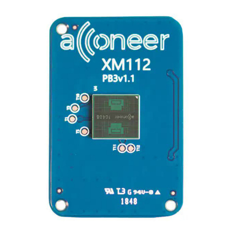
Acconeer XE123 User manual

Entry+ module EVK hardware user guide
- XE123/124

Entry+ module EVK hardware user guide
Page 2 of 28
© 2022 by Acconeer – All rights reserved 2022-07-06
Entry+ module EVK hardware user guide
- XE123/124
Author: Acconeer
Version 1.0: 2022-07-06
Acconeer AB

Entry+ module EVK hardware user guide
Page 3 of 28
2022-07-06 © 2022 by Acconeer – All rights reserved
Table of Contents
1. Overview of the XE123/124 Entry+ Module Evaluation Kit .......................................................... 4
1.1. Introduction ............................................................................................................................. 4
1.2. Getting Started ......................................................................................................................... 5
2. Software for the EVK ...................................................................................................................... 6
2.1. SW download .......................................................................................................................... 6
2.2. SW API Description ................................................................................................................ 6
3. The EVK Hardware ......................................................................................................................... 7
3.1. XE123/124 Evaluation Board .................................................................................................. 9
3.1.1. Overview ......................................................................................................................... 9
3.1.2. Power ............................................................................................................................. 11
3.1.3. Not Mounted Components ............................................................................................ 11
3.1.4. Electrical Schematics..................................................................................................... 12
3.1.5. Bill of Material .............................................................................................................. 16
3.1.6. Component Placement Drawing .................................................................................... 16
3.1.7. Connectors ..................................................................................................................... 18
3.2. XM123/XM124 Entry Module .............................................................................................. 20
3.2.1. Overview ....................................................................................................................... 20
3.2.2. Bill of Material .............................................................................................................. 23
3.2.3. Land Grid Array ............................................................................................................ 23
4. Safety ............................................................................................................................................. 25
4.1. Electrostatic precautions ........................................................................................................ 25
5. Regulatory Information ................................................................................................................. 26
6. Revision History ............................................................................................................................ 27
7. Disclaimer ..................................................................................................................................... 28

Entry+ module EVK hardware user guide
Page 4 of 28
© 2022 by Acconeer – All rights reserved 2022-07-06
1. Overview of the XE123/124 Entry+ Module
Evaluation Kit
1.1. Introduction
The XE123/124 Entry+ Module Evaluation Kit (The EVK) is a development platform targeting
straight-forward use cases where small size, low cost and low power is key.
The EVK features Acconeer’s XM123 or XM124 Entry+ module, including the A111 radar sensor.
The A111 radar sensor is an optimized low-power, high-precision 60 GHz radar with antenna in
package (AiP) and integrated baseband. Together with the ARM® Cortex®-M4 STM32L431 MCU,
the XM123/124 Entry module becomes a cost- and size-optimized low-power radar sensor.
The A111 is based on pulsed coherent radar technology (PCR). It has leading-edge patented sensor
technology with pico-second time resolution. The A111 sets a new benchmark as far as power
consumption and distance accuracy are concerned and it comes fully integrated in a small package of
29 mm2.
The A111 can measure absolute distance with mm accuracy up to a range of 2 m with a continuous
sweep update frequency of up to 600 Hz. With the use of a dielectric lens the range can be
significantly longer.
The A111, 60 GHz radar is not compromised by natural sources of interference such as noise, dust,
color, direct or indirect light.
The EVK consists of:
1 XE123/124 Evaluation board with an XM123 or XM124 Entry module soldered onto it.
The XE123/124 is compatible with Acconeer LH132 lens kit (LH132 is also compatible with
evaluation kit XE132). LH132 is sold separately.

Entry+ module EVK hardware user guide
Page 5 of 28
2022-07-06 © 2022 by Acconeer – All rights reserved
1.2. Getting Started
A Quick Installation Guide is available at https://youtu.be/PTcQ0FpRz7E
This short instruction video will ensure a smooth setup and installation. As an alternative you can also
find a guide in pdf-format at https://developer.acconeer.com.

Entry+ module EVK hardware user guide
Page 6 of 28
© 2022 by Acconeer – All rights reserved 2022-07-06
2. Software for the EVK
2.1. SW download
The SW is available for download at https://developer.acconeer.com. Here you will find both a
Software Development Kit and a Module Server version. SW User Guides can be downloaded at the
same site.
2.2. SW API Description
The Acconeer SW comes with an API (Application Programming Interface). Acconeer provides
several service-oriented example and reference applications, as well as customer guidelines for
application development when utilizing the API. All APIs provided by Acconeer are documented.
Unzip the SW zip file downloaded from Acconeer’s download site. In the file structure, please locate
/doc folder from where API documentation in HTML format is found at doc/html/index.html.

Entry+ module EVK hardware user guide
Page 7 of 28
2022-07-06 © 2022 by Acconeer – All rights reserved
3. The EVK Hardware
In Figure 1 the block-diagram of the XE123/124 is shown. Figure 2 shows the XM123/124 block-
diagram.
Figure 1 The block-diagram of the XE123/124.
USB1 Connector
5V
Boot0
NRST
Button
XE123/124
V_EXT (1.8V)
GPIO pin
header
(1.8V signal
levels)
Solderbridge
Power pin
header
SWD
connector
NRST
3.3V
LDO
5V to 3.3V
LDO
3.3V to 1.8V
Level shifter
3.3V to 1.8V
USB/UART
converter,
CP2105
1V8
V_MISC
DFU
Button
VIN
Power
switch
Selection
switch
PS_ENABLE
PS_ENABLE*
VIN_VIO
XM123 / XM124
* PS_ENABLE is an optional
signal. By default the power
switch is ON and
VIN_VIO=VIN
LED
1V8
3.3V

Entry+ module EVK hardware user guide
Page 8 of 28
© 2022 by Acconeer – All rights reserved 2022-07-06
Figure 2. The block-diagram of XM123/124.
24MHz XTAL
XM123/XM124
BOOT0
NRST
ENABLE
INTERRUPT
CTRL
A111
STM32L431CBY6
1V8
Land Grid Array
CPU
(32-bit, 80MHz
Cortex M4)
Flash
(128kB)
RAM
(64kB)

Entry+ module EVK hardware user guide
Page 9 of 28
2022-07-06 © 2022 by Acconeer – All rights reserved
3.1. XE123/124 Evaluation Board
3.1.1. Overview
The XE123/124 is an evaluation board including the XM123 or XM124 Entry+ module. It makes the
interfaces from the XM123/124 module accessible for evaluation and debug. It also enables flashing
of the XM123/124 via USB-UART or SW-DP. The XM123/124 Entry module is included in the
XE123/124 Evaluation board. In Picture 1 and Picture 2 you will find the XE123 and XE124 front
sides where the XM123 and XM124 is mounted. Picture 3 shows the back side of XE123/XE124.
Picture 1. The XE123 top side where XM123 is mounted.

Entry+ module EVK hardware user guide
Page 10 of 28
© 2022 by Acconeer – All rights reserved 2022-07-06
Picture 2. The XE124 front side with XM124 mounted.
Picture 3. The XE123/XE124 back side.

Entry+ module EVK hardware user guide
Page 11 of 28
2022-07-06 © 2022 by Acconeer – All rights reserved
3.1.2. Power
In the text below, the reference designators refer to the Electrical Schematic of XE123/XE124 in
chapter 3.1.4.
The XE123/124 is powered via the USB connector J1 and/or via the pin header J5. The USB 5V
power domain supplies the USB-UART chip (U2). If the USB-UART interface is not used, a
dedicated USB charger can be used.
The XM123/XM124 module mounted on the XE123/124 can be powered either from a 1.8V LDO
(U5) which is supplied from the USB 5V power domain or from “V_EXT” in the J5 pin header.
V_EXT should be 1.8V.
The power source for XM123/XM124 is determined by the setting of the switch “SW3”. When the
LED D4 on the XE123/124 is lit, the XM123/XM124 is powered
It should be noted that regardless of if “V_EXT” or “1.8V” is used to power XM123/XM124, the LED
D4 will consume power since it is connected to “V_MISC”. If one wants to measure only the current
consumed by XM123/XM124, power should be supplied to XE123/124 via the pin “VIN” (pin 4 in
pin header J5). In this case, the solder-bridge “SB12” should be cut. This way, all components on
XE123/XE124 are supplied from the 1.8V LDO, but XM123/XM124 is supplied from the external
power supply. D4 will not indicate if XM123/XM124 is powered after SB12 has been cut.
The intention of the power pin header J5 is that it can be used both for supplying power to
XM123/XM124 and for measuring current over a measurement resistor. SB12 is a short-circuited
solder-bridge, but the customer can change it to a low-value measurement resistor with high accuracy
to perform very accurate measurements of the XM123/XM124 current. See Table 2 for the pin
assignment of pin header J5.
To minimize the current consumption of the XM123/XM124 module, the voltage to “1V8”
(VIN_VIO) can be turned off when the A111 radar sensor is disabled (ENABLE=0). To do this, the
power switch U7 must be controlled by a GPIO of your choice from XM123/XM124. If a GPIO on
pin header J2 is connected to the signal “PS_EN” (PIN 2 on J2), and solder bridge “SB11” is cut, the
power switch ON/OFF state is controlled by this GPIO. The SW to do this is not provided by
Acconeer and must be implemented by the customer. By default, the power switch U7 is always on.
3.1.3. Not Mounted Components
As can be seen in the schematic in chapter 3.1.4, USB connector J4 and several other components are
“No Mount”. These components are related to the FTDI I2C-USB bridge chip FT4222H which can be
mounted on the PCB. It was added for internal Acconeer use, but customers are of course free to
mount these components if they wish. The I2C interface is also accessible in pin header J2. Refer to
Table 4.

Entry+ module EVK hardware user guide
Page 12 of 28
© 2022 by Acconeer – All rights reserved 2022-07-06
3.1.4. Electrical Schematics
On the following pages, please find the Electrical Schematics for XE123/124:

Entry+ module EVK hardware user guide
Page 13 of 28
2022-07-06 © 2022 by Acconeer – All rights reserved

Entry+ module EVK hardware user guide
Page 14 of 28
© 2022 by Acconeer – All rights reserved 2022-07-06

Entry+ module EVK hardware user guide
Page 15 of 28
2022-07-06 © 2022 by Acconeer – All rights reserved

Entry+ module EVK hardware user guide
Page 16 of 28
© 2022 by Acconeer – All rights reserved 2022-07-06
3.1.5. Bill of Material
Table 1 shows the BOM for the XE123/124
Table 1 The BOM for the XE123/124.
Designator Name Qty
Value Tolerance
Voltage
rating Manufacturer
C4, C8, C9, C10,
C11, C18, C30
Capacitor 1uF,
metric 1005 7
1µF 20% 10V
C6
Capacitor 4.7uF,
metric 1005 1
4.7µF 20% 10V
C1, C5, C13, C19,
C24, C27, C28, C29
Capacitor 100nF,
metric 1005 8
100nF 20% 10V
R7, R14
Resistor 0 Ohm,
metric 1005 2
0 1%
R1
Resistor 4.7 kOhm,
metric 1005 1
4.7k 1%
R2, R5
Resistor 5.1 KOhm,
metric 1005 2
5.1k 1%
R6
Resistor 10 Ohm,
metric 1005 1
10 1%
U1, U3 74AVCH4T245GU 2
NXP Semiconductors
J1 632723300011 1
Wurth Electronics
U2 CP2105-F01-GM 1
Silicon Labs
D2, D3 ESD8111PFCT5G 2
ON Semiconductor
D1 ESDM3551MXT5G 1
ON Semiconductor
SW1, SW2 EVPAA502W 2
Panasonic
J6
FTSH
-
105
-
01
-
F
-
DV
-
P-TR 1
Samtec
SW3 JS102011JCQN 1
ITT C&K
D4 LTST-C193KRKT-5A 1
Vishay Lite-On
U5 NCP161BMX180TBG
1
ON Semiconductor
U4 NCP167BMX330TBG
1
ON Semiconductor
U7
SIP32431DNP3-
T1GE4 1
Vishay Siliconix
J5 TSM-102-01-L-DV-P 1
Samtec
J2 TSM-110-01-F-DV 1
Samtec
J3 XM124 or XM123 1
3.1.6. Component Placement Drawing
In Picture 4 and Picture 5 the component placement drawing of XE123/XE124, top and bottom side,
are found:

Entry+ module EVK hardware user guide
Page 17 of 28
2022-07-06 © 2022 by Acconeer – All rights reserved
Picture 4. The component placement of XE123/XE124 top side.

Entry+ module EVK hardware user guide
Page 18 of 28
© 2022 by Acconeer – All rights reserved 2022-07-06
Picture 5. The component placement of XE123/XE124 bottom side.
3.1.7. Connectors
3.1.7.1. Power pin header (J5)
The power pin header J5 provides the possibility to supply the XM123/XM124 module with power
from an external power supply. In Table 2, the pin assignment of J5 is shown:
Table 2. The pin assignment of the power pin header J5.
Pin Number
Signal
Pin Number
Signal
1 V_EXT 2 GND
3 V_MISC 4 VIN

Entry+ module EVK hardware user guide
Page 19 of 28
2022-07-06 © 2022 by Acconeer – All rights reserved
3.1.7.2. 2x5 JTAG/SWD pin header (J6)
The 2x5 JTAG/SWD pin header (1.27mm pitch) contains the signals needed for flashing the
XM123/XM124 MCU via the SWD interface. The pinout matches that of the Cortex 10-pin
JTAG/SWD Connector and is found in Table 3.
Table 3. The pinout of J6.
Pin Number
Signal
Pin Number
Signal
1
VIN
2
SWD_IO
3
GND
4
SWD_CLK
5 GND 6 NC (no TRACESWO
available)
7 NC 8 NC
9 GND 10 NRESET
3.1.7.3. 2x10 pin header (J2)
The 2x10 pin header (2.54mm pitch) contains miscellaneous GPIOs from the XM123/XM124. The
pinout is found in Table 4.
Table 4. The pinout of J2.
Pin Number
Signal
Pin Number
Signal
1 UART_TX_1V81 2 PS_ENABLE
3 UART_RTS_1V82 4 MISC_GPIO2_BOOT0
5 UART_RX_1V83 6 MISC_GPIO1
7 UART_CTS_1V84 8 MISC_GPIO0
9 WAKE_UP_1V8 10 DEBUG_UART_RX_1V83
11 MCU_INT_1V8 12 DEBUG_UART_TX_1V81
13 I2C_ADDRESS 14 GND
15 I2C_SDA 16 NRESET
17 I2C_SCL 18 SWD_CLK
19 GND 20 SWD_IO
3.1.7.4. Switches and buttons
There is one switch on XE123/124. SW3 determines if XM123/XM124 is powered from the 1.8V
LDO (U5) on XE123/124 or from an external power supply via pin header J5 (V_EXT).
1 This signal is connected to RX on XM123/XM124. If external UART device is connected, this pin should be
connected to TX of external device.
2 This signal is connected to CTS on XM123/XM124. If external UART device is connected, this pin should be
connected to RTS of external device.
3 This signal is connected to TX on XM123/XM124. If external UART device is connected, this pin should be
connected to RX of external device.
4 This signal is connected to RTS on XM123/XM124. If external UART device is connected, this pin should be
connected to CTS of external device.

Entry+ module EVK hardware user guide
Page 20 of 28
© 2022 by Acconeer – All rights reserved 2022-07-06
There are two buttons on the XE124. SW1 controls the signal “BOOT0” connected to XM124 and
SW2 controls “NRESET” connected to the XM124. In Table 5 the state of the buttons and the
corresponding signal states are listed.
Table 5. The states of the buttons SW1 and SW2.
Button
Open (default)
Closed
SW1 BOOT0=0 BOOT0=1
SW2 NRST=1 NRST=0
3.2. XM123/XM124 Entry Module
3.2.1. Overview
The XM123 or XM124 Entry Module is included in the XE123/124 design and soldered on the top
side of the XE123/XE124 via a Land Grid Array pattern on the bottom side of the PCB. In Picture 6
below the top and bottom side of XM123 is shown. In Picture 7 the top and bottom side of XM124 is
shown.
Picture 6. The top and bottom side of XM123.
Picture 7. The top and bottom side of XM124.
This manual suits for next models
1
Table of contents
Other Acconeer Control Unit manuals
Popular Control Unit manuals by other brands

ADTRAN
ADTRAN T400 Installation & maintenance

BELL LABS INNOVATIONS
BELL LABS INNOVATIONS Lucent Stinger Series Guide

LDM
LDM RV 102 Instruction for installation and maintenance

resideo
resideo V8200 installation instructions

Tanda
Tanda TX7210 Installation and operation manual

Bluegiga
Bluegiga WT11-A Design guide