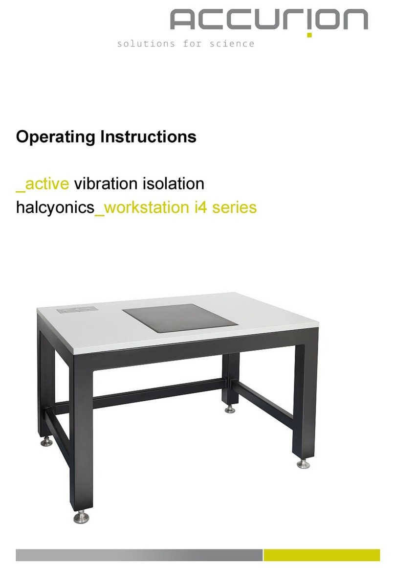
Accurion Halcyonics i4 Series User manual

Operating Instructions
_active vibration isolation desktop unit
halcyonics_i4 series

Contents
1Introduction ..................................................................................................................... 3
2Unpacking the i4 System ................................................................................................ 3
3Symbols used in these Instructions.................................................................................3
4Safety Information ........................................................................................................... 4
General Warnings.............................................................................................................. 4
Electrical Safety................................................................................................................. 4
Mechanical Safety ............................................................................................................. 4
Intended Use..................................................................................................................... 4
5Getting Started and Operation........................................................................................ 5
Setting Up the System ....................................................................................................... 5
Start-up.............................................................................................................................. 5
Automatic Load Adjustment and Transport Locking Mode ................................................. 6
Using Active Vibration Isolation ......................................................................................... 7
Overmodulation of the System........................................................................................... 7
6Appendix.......................................................................................................................... 8
Care and Maintenance .................................................................................................... 8
EMC Test Report............................................................................................................... 9
Specifications .................................................................................................................. 10
Dimensions of the Isolator .............................................................................................. 11
Transmissibility ................................................................................................................ 12
Settling Time ................................................................................................................... 12
Dynamic Stiffness............................................................................................................ 12
Accurion Offices .............................................................................................................. 13
- 2 -

1. Introduction
Thank you for purchasing the halcyonics_i4 system. By selecting this device you have acquired a top-of-
the-line active vibration isolation equipment. We feel confident that our system will meet your
expectations and provide the best possible performance for your specific application.
Please read the operating instructions carefully to set up the i4 system correctly.
We hope you enjoy working with your halcyonics_i4!
2. Unpacking the i4 System
After unpacking the system, please check whether the package contains all components.
Equipment supplied for the halcyonics_i4 system:
1 halcyonics_i4 system
1 power cord
1 power supply
1 instruction manual
3. Symbols used in these instructions
Warning symbol
Important note
Action that the user is required to take
- 3 -

4. Safety Instructions and Warnings
Please read through the following safety instructions and warnings carefully before using this equipment.
General Warnings
Do not operate the system in a potentially explosive or humid environment. Do not switch on the system
if there is any visible damage or if you think it might be damaged. In this case, turn off the power
immediately and notify our distributor in your area or contact Accurion’s headquarters in Germany
directly.
Electrical Safety
This system may be operated only on AC grounded power. Do not interrupt the protective grounding
conductor under any circumstances. If you plan to use a power cable other than the standard power cord
supplied with this equipment, first check that the protective grounding conductor is connected.
Before starting to operate this equipment, check the voltage rating to be sure that it matches your local
voltage. For further information, please refer to the specifications on page 10.
Only the certified, external power supply supplied with the system must be used.
Finish the set up and installation before attempting to plug it into an electrical outlet. Never open the
equipment housing. Only authorized and qualified personnel may service or repair the equipment.
The device must be connected to an easily accessible supply socket so that in the event of a
malfunction, the supply plug can be removed quickly.
Mechanical Safety
Ensure that the equipment rests on a stable surface that can safely support the weight of this instrument.
Please note that you need to activate the transport/relocation locking mode before you
transport or move the equipment! For further instructions, please refer to the section “Automatic
Load Adjustment and Transport Locking Mode” on page 6.
Intended Use
The system is suited to isolate various measurement equipment from building vibration and other
disturbing influences. Any other use is not permitted.
Never use the isolation system in mobile environments or outside the specified environmental
and operational requirements, see page 10.
DIN and European Standards, European Council Directives
Halcyonics i4 systems conform to the requirements currently valid for electrical safety according to EC
Directive 2014/35/EU and for electromagnetic compatibility according to EC Directive 2014/30/EU. This
equipment has been tested and found to comply with the following standards EN 61010-1:2010.
- 4 -

5. Getting Started and Operation
Setting Up the System
To obtain best performance from the halcyonics_i4, set it up on a stable, rigid and flat surface. For
optimal operating results, the planarity of the support surface should be 0.5 mm.
If you set up the i4 system on a table or bench frame, make sure that the table is distortion-free and stiff.
Although most tables and bench frames have sufficient resistance to vertical vibration, they are relatively
sensitive with respect to horizontal vibration. This causes amplification of structure and airborne noise.
Therefore, to set up your vibration isolation equipment, select a place with a vibration level that is as low
as possible. Vibration generated at this place should not exceed velocities of 500 μm/s.
Operating the system at low temperatures may cause malfunctioning. If the equipment is brought
from a cold environment into a relatively warmer one, we recommend that you wait approx. 2 – 3
hours before plugging it into AC power and switching on the power.
Start-up
Set up the system on a flat, stable surface at your work area.
Connect the external power supply to AC power (main supply) and to the i4.
Center your application on the top plate of the i4 system.
Turn on the power switch on the front panel of the system.
Press the Load Adjust button for automatic load adjustment (see page 6)
Set the switch for active isolation to on, blue LED is on (see page 7)
Power switch Isolation switch Load adjust switch
- 5 -

Automatic Load Adjustment and Transport Locking Mode
The top plate of the system is supported by four steel springs. These springs carry the load placed on
top. For the initial installation or after load changes these springs have to be pre-stressed according to
the weight of the setup. This is done by electric motors via an electronic circuit. This procedure is called
„automatic load adjustment“. The objective of the load adjustment is to elastically support the top plate
by the springs.
The halcyonics_i4 systems have a combined automatic load adjustment and transport locking mode
feature. Both functions are controlled using the "Load Adjust" button The following modes can be
selected depending on the number of times you press the button. The LEDs show the selected mode as
follows:
Green – load adjustment
LED off – neutral
Red – transport locking mode
The "load adjustment" mode (green LED) is used for automatic, load-dependent adjustment of the
system. When you set up the system and press this button, the system will start the load adjustment.
For initial adjustment and for changing the loading conditions, the green mode has to be selected.
During the activation of the green LED, the system will check at intervals whether the load on the
system has changed and will automatically move the top plate into the optimal position when necessary.
If this automatic adjustment is not desired, please turn the LA-Automatic off by pressing the load adjust
button once so that the LED is off. During the load adjustment of the i4 system, the active isolation is
interrupted.
The “neutral” mode (LED off) is selected to deactivate the automatic load adjustment and to avoid the
self-adjustment of the system. This way the motors of the load adjustment do not start to run at an
unwanted time. Once you switch on the system power for the first time, the i4 system will be in the
"neutral" mode. At this point, select the "load adjustment" mode. As soon as the stepper motors stop
you can switch to "neutral" and the system is ready to operate.
During transportation the halcyonics_i4 system always has to be locked! In the lock mode a rigid
mechanical contact between the top and the bottom of the system prevents the sensitive components
from damage. To lock the system, change the load adjustment setting to the "transport locking
mode" (red LED), and the four steel springs will be automatically pre-stressed up to the maximum.
Press and hold the
button for 4 seconds!
- 6 -

The system may only be transported or moved in the transport-locked condition!
There must not be any load on top of the isolation system during transport!
To change the different modes, it is necessary to press and hold the button for some seconds.
Using Active Vibration Isolation
Once you have started up the system, press the “isolation” button on the front panel to enable the active
vibration isolation. Now the system initializes, which is shown by a flashing blue LED. When the system
initializes for the first time or after a long interval, this process can take up to 30 seconds. When the blue
LED remains lit, the active vibration isolation is activated.
Overmodulation of the System
The i4 has been designed to compensate vibration amplitudes up to 500 µm/s. If vibrations significantly
exceed this level the system changes to the stand-by mode, indicated by a flashing blue "Isolation" LED.
After the overload excitation is stopped, the isolation mode will automatically be turned on again. After a
severe overload the system may take up to 30 seconds to reach full active isolation performance, but
normally only a few seconds are required.
The active vibration isolation will be automatically switched off during overmodulation of the
system. Once this interference has subsided, the system will re-initialize and, after a few seconds,
automatically resume to the active isolation mode. This procedure does not require any action
from the user.
- 7 -

6. Appendix
Care and Maintenance
The i4 system has been carefully designed and manufactured by Accurion. To maintain this equipment
and the validity of your warranty, you should observe the following recommendations:
Store the system in a dry place. Never expose it to rain, liquids or dampness. The minerals
contained in these liquids may lead to short-circuits or corrosion of the electronic circuits.
Where possible, avoid operating and storing the system in dirty or dusty environments as
this may otherwise damage the electronic or mechanical components.
Do not store the system in hot environments. Operating the system at high temperatures may
compromise its performance and reduce its lifetime.
Do not store the system in cold environments. When the temperature rises to normal room tem-
perature, moisture condenses inside the system and causes a circuit failure. If you need to trans-
port the system from a cold environment to a warmer one, wait approx. 2 – 3 hours before
plugging it into AC power and switching on the power.
Do not drop the system or shake it, and never expose it to impact or blows. Improper handling
can damage the integrated electronics and mechanical components in the system.
To clean, wipe off dust from the exterior surfaces of the system using a lint-free cloth.
For cleaning, do not use any aggressive cleaning agents.
- 8 -

EMC Test Report
- 9 -

Specifications
- 10 -
Available Standard Versions
halcyonics_i4 halcyonics_i4medium halcyonics_i4large
halcyonics_i4 M6/25 halcyonics_i4medium M6/25 halcyonics_i4large M6/25
halcyonics_i4medium 150 kg halcyonics_i4large 150 kg
halcyonics_i4medium 150 kg M6/25 Halcyonics_i4large 150 kg M6/25
Performance Specifications
Isolation Technology: Accurion control technology based on piezoelectric type acceleration pickup, fast
signal processing and electro-dynamic type force transducers
Force directions: Active compensation in all six degrees of freedom
Isolation performance: > 5 Hz = 25 dB (94.4%); >10 Hz = 40 dB (99.0%)
Active bandwidth: 0.6 – 200 Hz*
Settling time: 300 ms**
Response time: 0.5 ms***
Max. correction forces: Vertical ± 8 N; horizontal ± 4 N
Load capacity: i4: 0 – 120 kg (0 - 265 lbs) / i4medium + i4 large: 0 - 105 kg (231 lbs) or
40 - 150 kg (88 - 330 lbs)
Other Specifications
Dimensions: i4: 400 x 500 x 90 mm (15.7“ x 19.7“ x 3.5“) / i4medium: 600 x 600 x 90 mm (23.6“
x 23.6“ x 3.5“) / i4large: 550 x 700 x 92 mm (21.7“ x 27.6“ x 3.6“)
Weight: i4: 20 kg (44 lbs) / i4medium: 37 kg (81 lbs) / i4large: 40 kg (88 lbs)
Table top material: Powder coated aluminium
Top plate surface flatness: ± 0.10 mm over complete surface
Max. compensation level: 500 µm/s at 6 Hz and with a load of 60 kg (132 lbs)**
Repeatability of load
adjustment: 120 µm
Environmental and Operational Requirements
Electrical voltage: 100 - 240 V AC/47 – 63 Hz
Fuse (inside i4): 250V / F3,15A (Fuse may be changed by authorized service staff only!)
Power consumption: Typically 40 - 45 W
Operating temperature: 15 – 40°C (59 – 104 F)
Operating humidity: 0 – 60%
Operating altitude: < 2500 m (8100 ft)
Operating condition: Use in non-mobile laboratories only
Pollution degree: 2 (according to DIN EN 61010-1)
* Floating table top is supported by steel springs; low-pass characteristics of spring-mass combination
dominates the dynamic behaviour above 200 Hz.
** The settling time and maximum compensation level depend on several conditions, such as payload, frequen-
cy, load distribution and height of the payload. For that reason this value should be considered as an estima-
tion.
*** The response time determines when the system starts to actively isolate an incoming vibration after detec-
tion by the sensors.

Dimensions of the Isolator
- 11 -
i4large system
i4medium system
i4 system

Transmissibility
Transmission graph i4, measured at a velocity of 100 µm/s with a payload of 20 kg (44 lbs)
Settling Time Dynamic Stiffness
- 12 -
Dynamic isolator stiffness (green) of Accurion’s
i4 system compared to a commercially available
passive air-damped isolation system (blue).
Due to their higher dynamic stiffness,
Accurion’s systems are less sensitive to direct
forces affecting the isolation system.
Settling time of a Halcyonics_i4 system
(green) compared to a conventional air-
damped vibration isolation system (blue),
made by one of the major manufacturers of
optical tables and vibration isolated labora-
tory desks.

Accurion Offices
Headquarters Germany North America
Accurion GmbH Accurion Inc.
Stresemannstrasse 30 20045 Stevens Creek Blvd., Suite 2E
37079 Goettingen Cupertino, CA 95014
Germany USA
Phone: +49-[0]551-99960-0Phone/Fax: (+1) 408 642 1446
Fax: +49-[0]551-99960-10 E-Mail: [email protected]m
E-Mail: info@accurion.com www.accurion.com
www.accurion.com
India China
Accurion Scientific Instruments Pvt., Ltd.Accurion Scientific Instruments (Shanghai) Co., Ltd.
Flat 402, Wing 2, Balaji Lakeside Marvel Rm. 502, Xuhui Commercial Building
#1413/2A, 7th Cross, 1st Main Road No. 168, Yude Road, Xuhui District
BHCS Layout, Uttarahalli Shanghai 200030
Bangalore 560061 China
India
Phone/Fax: +86-[0]21-5017-9099
Phone: +91-[0]98450 04273 Mobile: +86-[0]138-1861-2900
E-Mail: shar[email protected] E-Mail: FZ@accurion.cn
www.accurion.com www.accurion.com.cn
Installation Video
- 13 -
This manual suits for next models
10
Table of contents
Other Accurion Laboratory Equipment manuals
Popular Laboratory Equipment manuals by other brands

Envair Lab
Envair Lab ecoChem operating & maintenance manual

Thermoline Scientific
Thermoline Scientific TU-1 operating instructions

THORLABS
THORLABS SD-OCT Telesto Series user manual

Thomas
Thomas 351 user guide

Heidolph
Heidolph Hei-VOLUME Distimatic Pro operating instructions

Fritsch
Fritsch premium PULVERISETTE 14 operating instructions