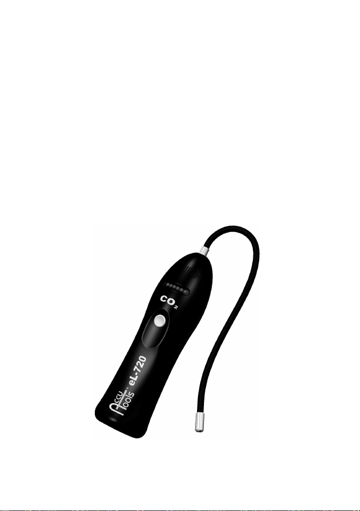
AccuTools eL-720 User manual

eL-720
CLI20206
Carbon Dioxide Gas
Leak Detector
User’s Guide

eL-720 User’s Guide
1
Congratulations on the purchase of the AccuTools™ eL-720
Carbon Dioxide Gas Leak Detector, the most technologically
advanced instrument of its kind. The eL-720’s minimal power
requirements, small size and high sensitivity combine to create a
tool which is easy to handle and ultra effective at locating even
the most difficult-to-find leaks.
Please read this entire manual prior to operation to ensure
trouble-free use of the eL-720.
TECHNICAL DATA
Dimensions 8” x 2.5” x 2.25” (20.3 cm x 6.3 cm x 5.7 cm)
Weight 15 oz. (425 grams) with Batteries
Batteries 4 x 1.5V 'AA' Alkaline Batteries (6 VDC)
Battery Life 20 hours
Sensitivity (High) < 400 ppm at 350 ppm ambient
Sensitivity (Low) < 4,000 ppm at 350 ppm ambient
Sensor lifetime > 2 years
Operating temperature 32 –122°F (0 –50°C)
Warm up time 10 sec.
Response time < 1 second
Reset time < 1 second
Probe length 12” (30 cm)

eL-720 User’s Guide
2
WARNING: The eL-720 contains an optical sensor that must remain
free of moisture and debris. Failure to operate the unit without a
filter may cause the sensor to become contaminated. This will result
in a sensor malfunction as indicated by the failed sensor alarm.
INSTRUCTIONS
1. Press the button to turn the unit on. Unit will beep 3 times and all
LEDs will light.
2. The unit will warm up and self-calibrate for 10 seconds, after which a
constant beeping will be heard.
3. Test the unit by exhaling gently into the probe tip. Human breath
contains enough CO2to cause a full-scale alarm in High Sensitivity.
4. Unit turns on in the high sensitivity level (400 ppm). For zeroing into
large leaks, change to the low sensitivity level: Press the button
twice (double-click like a computer mouse). The LEDs will scan from
right to left and a sweeping sound effect of high to low pitch will be
heard. The sensitivity is now set for 4,000 ppm.
5. Double click again to change back to high sensitivity. The LEDs will
scan from left to right and a sweeping sound effect of low to high
pitch will be heard.
6. To reset the unit to the ambient level of carbon dioxide, press and
release the button. The LEDs will flash briefly to indicate the reset.
All levels of carbon dioxide less than the reset level will be ignored.
7. Move the probe towards a suspected CO2leak at a rate of less than
2 inches (50 mm) per second, no more than ¼ inch (5 mm) away
from the suspected source.
8. If a leak exists, the sound will increase in rate and pitch and the
LEDs will indicate the relative leak rate.
9. To turn the eL-720 off, press and hold the button for 1 second.
10. To conserve battery power, the eL-720 will automatically turn itself
off after 10 minutes of inactivity.

eL-720 User’s Guide
3
PROBE FILTER
The probe filter prevents dust and moisture from contaminating the
optical characteristics of the sensor. It should be replaced periodically.
Occasionally, the filter may become obstructed with dirt, dust, or
moisture. To determine if air is flowing properly into the eL-720 sensor,
gently exhale near the probe tip. The human breath contains enough
CO2 to cause a full alarm in high sensitivity mode. If the unit does not
alarm, replace the filter.
If the filter has become moist due to exposure to water or
condensation follow this procedure to prevent moisture from
contaminating the sensor:
1. Using a paper towel or shop rag, dry any moisture at the probe tip
prior to unscrewing the probe tip cap.
2. Unscrew the probe tip cap to expose the filter.
3. With a paper towel or shop rag, soak up any excess moisture that
may have collected on the filter and filter holder prior to removing the
filter. Also thoroughly dry both inside and outside of the probe cap.
4. Remove and discard the old filter, and replace with a new one.
5. Reassemble the probe tip cap. The unit is now ready for operation.
Failure to dry the filter parts as described above may result in
further contamination of the new filter, and the possibility of
residual moisture being drawn into the optical sensor, causing a
failed sensor alarm. If moisture is suspected of being drawn into the
sensor, clean the probe and sensor as described on page 4.

eL-720 User’s Guide
4
SENSOR
An eL-720 sensor is designed for a long, trouble-free life. The
sensor is tested and calibrated automatically each time the unit is
powered on. A failed or failing sensor will be indicated 3
seconds after power-on by a two-tone alarm and all LEDs
flashing.
CLEANING THE SENSOR
If moisture is suspected of contaminating the sensor, the probe
and sensor may be cleaned using this procedure.
1. IMPORTANT: Remove the sensor from the instrument as
directed on page 5.
2. Remove the probe tip cap and filter from the probe tip.
3. Blow compressed air into the probe tip to remove any residual
moisture from the probe.
4. Blow compressed air*into the inlet and outlet ports of the
sensor.
5. Place a few drops of distilled water or isopropyl alcohol into
both the inlet and outlet ports of the sensor.
6. Blow compressed air*into the inlet and outlet ports of the
sensor to remove any remaining liquid and thoroughly dry the
exterior of the sensor.
7. Install the sensor, and insert a new filter into probe tip. The
unit should now operate properly.
* Note: Do not exceed 50 psi pressure. Doing so may result
in the loss of the small o-rings in the inlet and outlet ports of
the sensor.

eL-720 User’s Guide
5
SENSOR REPLACEMENT
In the event of a failed sensor (as indicated by the Failed Sensor
Alarm), cleaning or replacement of the sensor is necessary. First,
clean the sensor as directed on page 4. If an alarm is still heard,
the sensor must be replaced. To replace the sensor:
1. Turn the power off.
2. Remove the sensor compartment cover by loosening the
sensor compartment cover screw.
3. Remove the 2 screws holding the sensor in place with a 1.5
mm hex wrench.
4. Grasp the old sensor with your fingers near the screw holes
and firmly lift out of the sensor compartment.
5. Firmly press the new sensor into the compartment, noting
alignment of the sensor connector tab and gas ports of the
sensor with the mating features in the instrument.
6. Firmly tighten sensor in place with 2 screws and 1.5 mm hex
wrench.
7. Replace and fasten sensor compartment cover.
Replacement Sensor Kit
Part Number ELS-7CO2

eL-720 User’s Guide
6
BATTERIES
ŸThe left-most (blinking) LED indicates the battery life, and
dims when the batteries approach end of life. Less than one
hour of battery life remains when the LED is completely dark.
•When the batteries no longer contain enough energy to power
the instrument reliably, a five second tone will be heard, after
which the eL-720 will power itself off.
ŸIf the unit is left on unattended, it will automatically turn off
after about 10 minutes to conserve batteries.
BATTERY INSTALLATION AND REPLACEMENT
1. Turn the power off.
2. Remove the battery cover from the back of the instrument by
loosening the battery cover screw and lifting the battery cover
off.
3. Insert 4 size ‘AA’ alkaline batteries, observing proper battery
polarity.
4. Replace battery cover and tighten battery cover screw.
MAINTENANCE
The eL-720 should provide years of service with little
maintenance aside from changing batteries, filters, and sensors.
The case may be cleaned with a shop towel moistened with water
and a mild detergent. Do not use solvent of any kind.
This manual suits for next models
1
Table of contents
Popular Gas Detector manuals by other brands

Gas Sense
Gas Sense GS-300.A Operation manual

RKI Instruments
RKI Instruments 65-2437RK-05 Operator's manual

ION
ION shawcity ARA DOCK4 quick start guide

CAMPERGUARD
CAMPERGUARD KL-QG05 quick start guide

Honeywell
Honeywell SEARCHLINE EXCEL PLUS Safety manual

RKI Instruments
RKI Instruments RIKEN RX-516 Operation manual