ACE Stoßdämpfer GmbH · Postfach 1510 · D-40740 Langenfeld · T +49 (0)2173 - 9226-10 (Technik -20) · F +49 (0)2173 - 9226-19 · [email protected] · www.ace-ace.comStand 03.2021 ACE
St
oßdämpfer
GmbH
·
www.ace-ace.com
2
1_22_00
1
9
Issue
05.2022
2
WARNING
If ACE rotary dampers are used where a failure of the
product could lead to personal injuries and/or material
damage, additional safety elements must be implemented.
Free-moving masses, such as lids, flaps, covers etc., can
lead to injuries by crushing during installation of the rotary
dampers. Secure moving flap/mass against falling down!
Intended use
ACE rotary dampers ensure the controlled opening and closing of
small covers, compartments and drawers. They can brake directly
at the pivot point or linearly via rack and pinion to attain a smooth
and quiet movement. Sensitive components are preserved. The
harmoniously gentle process increases the quality and value of
the product.
Description and function
On the rotary dampers with a partial rotation angle the fluid is
pressed from one chamber to another by the rotor movement. The
damping torque is determined by the viscosity of the fluid or the
dimensioning of the damping orifice or metering orifice. During
each reverse movement of the unilateral decelerating versions
there is a certain return damping torque that depends on the size.
ACE rotary dampers are maintenance-free and ready-to-install.
The damping direction can be rotating left or right. The outer
bodies are made of plastic. The dampers can be mounted directly
at the pivot point.
Safety information
Delivery and storage
- After delivery please check the rotary dampers for any damage.
- The rotary damper can become damaged if it falls. Carefully
remove rotary damper from the packaging.
- Rotary dampers can generally be stored in any position.
- Storage in the original packaging is preferred.
- Always store rotary dampers dry.
- The recommended maximum storage time is two years.
- Storage of rotary dampers is permissible at -20 °C to +70 °C.
Maintenance and care
Regularly check the rotary damper for oil loss and external dam-
age. Rotary dampers are machine elements that are subject to
continuous wear. Increased service life results in reduced braking
effect. If this is no longer sufficient, the rotary dampers must be
replaced or exchanged as appropriate.
Disassembly and disposal
Take account of environmental protection (recovery of problematic
substances) during disposal of the rotary dampers. The rotary
dampers are filled with silicone oil. The corresponding data sheet
is available on request. By design, the silicone oil cannot be
refilled. The rotary dampers cannot be repaired. Faulty brakes can
be sent to our service department for determination of the cause
of failure.
Calculation steps
1. Calculate torque for unfavourable angle
(see example on left: 0°).
2. Determine angular speed.
3. Choose a suitable rotary damper for the calculated torque.
4. With the aid of the damper performance curve, check whether
the rpm matches the desired speed.
5. If the rpm is too high – choose a higher torque.
6. If the rpm is too low – choose a lower torque.
Torque
M = L / 2 · m · g · cos α
(L / 2 = centre of gravity)
mMass in kg [1 kg = 9.81 N]
LFlap length in cm
nSpeed in rpm
Calculation example: Damping of a flap
In order to select a suitable rotary damper for the calculation
example shown, the length and the weight or centre of gravity of
the flap must be specified. Once the max. torque value with an
unfavourable angle of the flap has been determined, a suitable
brake is selected.
General instructions
This manual is for the disruption-free use of the product
types listed on page 1; its compliance is a prerequisite
for the fulfilment of any warranty claims.
Therefore, make sure to read this manual before use.
Always maintain the limits specified in the performance
table. Take into account the predominant environmental
conditions and restrictions. Note the regulations of
the trade association, TÜV or corresponding national,
international and European regulations. Installation and
commissioning only according to mounting instructions.
Calculation and design
In order to ensure an optimum fault-free and durable function of the rotary dampers, they must be correctly dimensioned and designed. The following parameters
must be known and used in the calculation.
- Temperature
- Damping torque
- Speed
- Cycle number
Should you have any further questions about the use of rotary dampers, please contact one of our ACE technicians.
For free calculation service, phone: +49 (0)2173 - 9226-20.
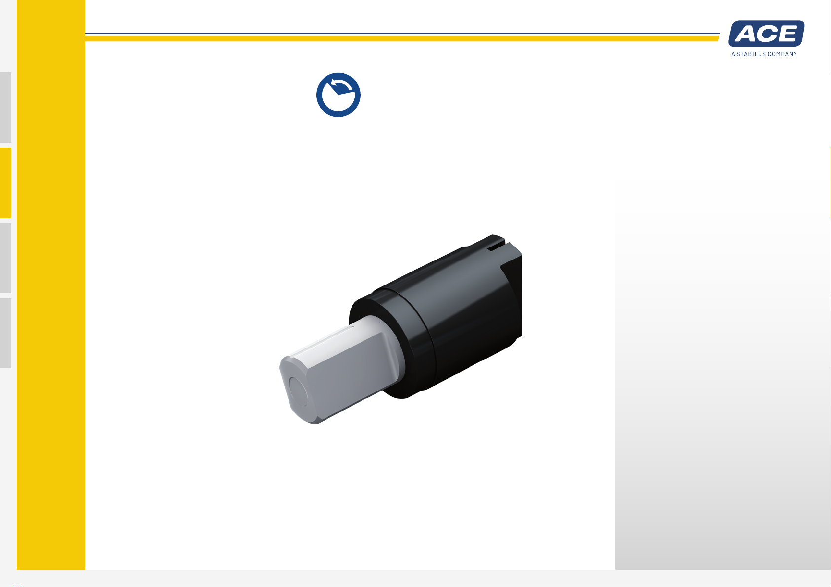
Rotary Damper FYN-P1 (partial rotation angle)
Manual