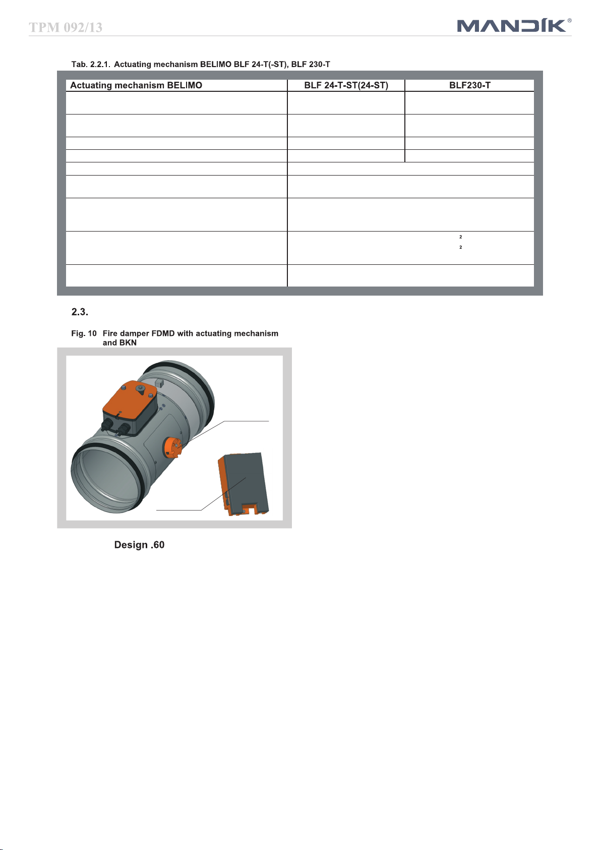
Mandik FDMD User manual


1
TPM 092/13
II. ENERAL INFORMATION 2
1. Description......................................................................................................................... 2
2. Damper Design............................................................................................................... 3
3. Communication and control devices................................................................................ 7
4. Dimensions, weights........................................................................................................... 10
5. lacement and Assembly.................................................................................................... 12
6. Statement of installations.................................................................................................... 15
7. Suspension of fire dampers................................................................................................. 23
III. TECHNICAL DATA 26
8. ressure loss...................................................................................................................... 26
9. Coefficient of local pressure loss......................................................................................... 26
10. Noise data......................................................................................................................... 27
VI. MATERIAL, FINISHIN 29
11. Material............................................................................................................................. 29
VII. INSPECTION, TESTIN 29
12. Inspection, testing............................................................................................................. 29
VIII. TRANSPORTATION AND STORA E 29
13. Logistic terms.................................................................................................................... 29
IX. ASSEMBLY, ATTENDANCE, MAINTENANCE AND REVISIONS 29
14. Assembly.......................................................................................................................... 29
15. Entry into service and revisions......................................................................................... 29
V. DATA OF PRODUCT 30
16. Data label.......................................................................................................................... 30
17. Quick review..................................................................................................................... 31
IV. ORDERIN INFORMATION 32
18. Ordering key..................................................................................................................... 32
I. CONTENT
These technical specifications state a row of manufactured sizes and models of fire dampers (further only dampers)
FDMD. It is valid for production, designing, ordering, delivery, assembly and operation.

2
TPM 092/13
Fig. 1 Fire damper FDMD, design .01 - damper with inner
mechanical control
Fig. 3 Fire damper FDMD, design .01v2 - damper with
outer mechanical control and mechanical control
cover
Fig. 4 Fire damper FDMD, design with actuating
mechanism
II. GENERAL INFORMATION
1. Description
Fig. 2 Fire damper FDMD, design .01v1 - damper with
outer mechanical control
1.1. Fire dampers are shutters in duct systems of air-conditioning devices that prevent spreading the
fire and combustion products from one fire segment to the other one by means of closing the air
duct in the points of fire separating constructions.
Dampers blade automatically closes air duct using a shutting spring or an actuating mechanism
back spring. The back spring of the actuating mechanism is started when the thermoelectrical
starting mechanism BAE 72B-S is activated, when a reset button on BAE 72B-S is pushed or
when a power supply of the actuating mechanism is stopped.
The damper is sealed with a silicon packing against smoke penetration after closing the blade. At
the same time, the damper blade is bedded in a material which enlarges its capacity and air
proofs the air duct.
Dampers have one inspection hole, since the shutting device and the inspection hole can be set
into the most advantageous position (with respect to the operation and manipulation with the
control device).

3
Terminalswitch
CLOSED
Terminalswitch
CLOSED
Terminalswitch
OPEN
Dampercharacteristics
CEcertifiedacc.toEN15650
TestedinaccordancewithEN13662
Classifiedacc.toEN135013+A1
FireresistanceEIS120,EIS90
External Casig leakage class min. C, Internal leakage class 3 (D=200 mm) and class 2
(D=100180mm)acc.toEN1751
CyclingtestinclassC10000acc.toEN15650
Corrosionresistantacc.toEN15650
ESCertificateofconformityNo.1391CPR0089/2014
DeclarationofPerfomanceNo.CDM/FDMD/001/14
HygienicassessmentoffiredampersReportNo.1.6/13/16/1
Workingconditions
Exactdamperfunctionisprovidedunderthefollowingconditions:
a)Maximumaircirculationspeed:12m.s
Maximumpressuredifference:1500Pa
b)DamperscouldbedisplacedintopositionCLOSEDonlyincasethatventilator,orAir
Handling Unit is switched off. The goal is the securing of proper closing and safe
functionofFireDamperincaseofFire.
c)Theaircirculationinthewholedampersectionmustbesecuredas steadyonwhole
surface.
Operationofthedampersdoesnotdependonthedirectionofaircirculation.Thedamperscan
belocatedinanarbitraryposition.
Dampersaresuitableforsystemswithoutabrasive,chemicalandadhesiveparticles.
DampersaredesignedformacroclimaticareaswithmildclimateaccordingtoEN6072133.
Temperatureintheplaceofinstallationispermittedtorangefrom20°Cto+50°C.
Designwithmechanicalcontrol

4
Design.01with mechanicalcontrolcan be complementedwith a limitswitch signallingofthe
damperbladeposition"CLOSED".Limitswitchisconnectedviadampercasing(.01),cableis
connecteddirectlytolimitswitch(.01v1)orlimitswitchisconnectedviamechanicalcontrolcover
(.01v2).
Design.01withmechanicalcontrolcanbecomplementedwithaterminalswitchessignalingof
the damper blade position "CLOSED" or "OPEN". Limit switches are connected via damper
casing (.01), cables are connected directly to limit switches (.01v1) or limit switches are
connectedviamechanicalcontrolcover(.01v2).
COM
black
NO
red
NC
white
Nominalvoltage,current DC30V;0,1A
Degreeofprotection IP67
Ambienttemperature 40°C85°C
DesignwithanactuatingmechanismBLF230TorBLF24T(furtheronly"actuatingmecha
nism").AfterbeingconnectedtopowersupplyAC/DC24Vor230V,theactuatingmechanism
displacesthedamperbladeintooperationposition"OPEN"andatthesametimeitprestretches
its back spring. When the actuating mechanism is under voltage, the damper blade is in the
position"OPEN"andthebackspringisprestretched.Timeneededforfullopeningoftheflap
blade from the position "CLOSED" to the position "OPEN" is maximum 140s. If the actuating
power supply is cut off (due to loss of supply voltage, activation of thermoelectrical actuating
mechanismorpushingtheresetbuttononthethermoelectricalstartingmechanismBAE72BS),
BAE72BS
Designwithmechanicalcontrolwithathermalprotectivefusewhichactuatestheshuttingdevice
within 120 seconds at latest after the nominal start temperature 72 °C has been reached.
Automaticinitiation ofthe shutting deviceis not activatedif the temperaturedoes not exceed
70 °C. In case that other start temperatures are required, thermal fuses with nominal start
temperature+104°Cor+147°Ccanbesupplied(thisrequirementmustbespecifiedintheorder).
Designwithactuatingmechanism

5
TPM 092/13
Fig. 8 Actuating mechanism BELIMO BLF 24-T(-ST)
Fig. 9 Actuating mechanism BELIMO BLF 230-T
the back spring displaces the damper blade into the breakdown position "CLOSED". The time of
displacing the blade from the position "O EN" to the position "CLOSED" takes maximum 16 s. In
case that the power supply is restored again (the blade can be in any position), the actuating
mechanism starts to re-displace the damper blade into the position "O EN".
A thermoelectrical starting mechanism BAE 72B-S, which contains three thermal fuses Tf1 and
Tf2/Tf3, is a part of the actuating mechanism. These fuses are activated when temperature
+72 °C has been exceeded (the fuse Tf1 when the temperature around the damper and the fuses
Tf2/Tf3 when the temperature inside the air-conditioning piping has been exceeded). After the
thermal fuse Tf1 or Tf2/Tf3 has been activated, the power supply is permanently and irreversibly
cut off and the actuating mechanism, by means of the pre-stretched spring, displaces the damper
blade into the breakdown position "CLOSED".
Signalling of blade positions "O EN" and "CLOSED" is ensured by two firmly set integrated limit
switches.
AC 24 V
~
12
+-
DC 24 V
S2S1 S3 S5S4 S6
M
BLF24-T, BLF24-T-ST
an insulation transformer.
Parrallel connection of other driver is possible.
BLF24 ST T: Design with connector plugs for communication
to network and communication device BKN230 24
Connection through
Pay attention to the power input data.
<5° <80°
BAE72B S
Tf1 Tf2 Tf3 LED
BLF230-T
M
AC230 V
2
1
NL1
S3S2S1 S6S5S4
For separation from the mains, a device that
insulates polar conductors must be at disposal
(Minimum distance between contacts 3 mm).
<5° <80°
BAE72B S
Tf1 Tf2 Tf3 LED
Parrallel connection of other driver is possible.
Pay attention to the power input data.

6
BAE72BS
BKN23024
Nominalvoltage AC24V50/60Hz
DC24V
AC230V50/60Hz
Powerconsumptionmotoring
holding
5W
2,5W
5W
3W
Dimensioning 7VA(Imax5,8A@5ms) 7VA(Imax150mA@10ms)
ProtectionClass III II
Degreeofprotection IP54
Runningtime motor
springreturn
40..75s
~20s
AmbientTemperaturenormalduty
safetyduty
nonoperatingtemperature
30°C+50°C
Thesafepositionwillbeattaineduptomax.75°C
40°C+50°C
Connectingmotor
auxiliaryswitch
cable1m,2x0,75mm
cable1m,6x0,75mm
(BLF24TST)withpoleplugs
Thermaltrips Tf1:ductoutsidetemperature72°C
Tf2/Tf3:ductinsidetemperature72°C
Designwiththecommunicationand supplydeviceBKN 23024andthe actuatingmechanism
BLF24TST.Itsimplifieselectricalwiringandinterconnectionoffiredamper.Itfacilitatesonsite
checkandenablescentralcontrolandchecksoffiredamperbymeansofasimple2conductor
wiring.
BKN23024functionsasadecentralizednetworkdeviceforsupplyingtheactuatingmechanism
BLF24TSTwithaspringbackdriveononehandandontheotherhandittransmitsthesignal
informingaboutthefiredamperpositionOPERATIONandFAILUREthrough2conductorwiring
tothe central. Controlcommand SWITCHED ON SWITCHED OFFfrom thecentralthrough
BKN23024goesthroughthesamewiringtotheactuatingmechanism.
Tosimplifytheconnection,theactuatingmechanismBLF24TSTisequippedwithconnecting
plugsthatareinserteddirectlytoBKN23024.BKN23024issuppliedwithaconductorandan
EUROplugtobeconnectedtothe230Vmains.
2conductorwiringisconnectedtoBKN23024bymeansofterminals6and7.
Ifthedriveissupposedtobecontrolledwithoutanysignalfromthecentral,itcanbeswitchedon
bymeansofabridgebetweentheterminals3and4.AgreenLEDpilotlightonBKN23024is
onwhenvoltageispresentinthedrive(AC24V).IfthebuttononBAE72Sisswitchedonorif
thepowersupply(e.g.byasignalfromELECTRICALFIRESIGNALISATION)isdisconnected,
thefiredamperpositionwillbe"FAILURE".
CommunicationandsupplydeviceBKN23024hastobeplacednearthedamper.Itisnecessary
foreasyconnectionofactuatingsystemequippedbyBKN23024device.
Designwiththecommunicationandsupplydevice

7
TPM 092/13
Fig. 11 Communication and Supply Device BKN 230-24
Tab. 2.3.1. Communication and Supply Device BKN 230-24
2
Communication and Supply Device BKN 230-24
Nominal voltage AC 230V 50/60Hz
ower consumption 3,5 W (operating position)
Dimensioning 11 VA (including actuating mechanism)
rotection Class II
Degree of protection I 42
Ambient Temperature
Storage Temperature
- 30 °C + 50 °C
- 40 °C + 50 °C
Connection - mains
- drive
- terminal board
Cable 0,9 m with EURO plug of 26 type
6 pole plug, 3 pole plug
screw terminals for conductor 2x1,5 mm
3.1. BKS 24-9A communication and control device is used for group control and checks of 1 to 9 fire
dampers with the actuating mechanism BLF 24-T-ST in connection with the supply and
communication device BKN 230-24. Signalisation of the damper position is individual; the
dampers can be controlled and tested only as a group. BKS 24-9A is intended for use in the
distribution board and displays the operation situations and failure reports of the connected fire
dampers. It is possible to signalise functions such as the damper position and failure reports or to
transmit them further to the system by means of integrated auxiliary switches. BKS 24-9A
receives signals from BKN 230-24 through the two-conductor wiring and issues control
commands. roper damper operation is indicated by two light LED diodes:
Control ON = position O ERATION
Control OFF = position FAILURE
If the fire dampers do not reach the given position in time tolerable for displacing, the appropriate
light diode FAILURE starts to flash and K1 contact is opened (current failure). In case that the
faulty damper finally reaches its given position, K1 is closed and the failure report light shines (the
failure is saved in memory).
K2 - the auxiliary contact - is used for signalisation of the flap position to the master device. Function
of this auxiliary contact can be programmed through the terminal 14 according to the Tab. 3.1.1.
3. Comm nication and control devices

8
TPM 092/13
Fig. 12 Communication and Control Device BKS 24-9A
3.2. BKS 24-1B communication and control device is used for control and checks of fire dampers with
the BLF 24-T-ST actuating mechanism in conjunction with the BKN 230-24 supply and
communication device. BKS 24-1B receives information about the situation of the fire damper
through the BKN 230-24 supply and communication device and issues controlling commands.
The device is intended for building in into the distribution board. Light diodes on the front side of
the device signalise the operating situations of the damper and breakdowns of the whole system.
Nonpotential auxiliary contacts enable connection to the master control system (signalisation of
the damper position, failure reports, release of the ventilators etc.).
Tab. 3.1.1. BKS 24 -9A contacts K1 and K2
K1 Function Contact
Situation State
Current Failure 15 16
No Failure 15 16
Programming K2 Auxiliary Contact
Function Interconnection State
K2 contact is on if all the
damperss are open 14 11
17 18
K2 contact is on if the damper
No. 1 is open 14 12
K2 contact is on if all the
dampers are closed 14 open
Function check can be done in the position O ERATION by means of pushing the TEST button.
While the button is pushed, the flap blade is turning into the position FAILURE. Fault function is
indicated by a report "FAILURE".
2
Tab. 3.2.1. Communication and Control Device BKS 24-9A
Communication and Control Device BKS 24-9A
Nominal voltage AC 24 V 50/60Hz
ower consumption 3,5 W (operating position)
Dimensioning 5,5 VA
rotection Class III (safe small voltage)
Degree of protection I 30
Ambient Temperature 0 + 50 °C
Connection Terminals for conductor 2 x 1,5 mm

9
TPM 092/13
While a flashing green LED pilot light signalises flap blade motion towards the given position, the
same pilot light reports reaching the required position when shining constantly. If the damper, with
respect to the given time, does not reach the required position, then a red LED pilot light starts to
flash and at the same time, the failure contact is active. Once the damper blade reaches the given
position, this contact is deactivated. The LED pilot light keeps flashing unless the failure is
unblocked by means of the RESET button.
Fig. 13 Komunikační a řídící přístroj BKS 24-1B
Tab. 3.2.1. Communication and Control Device BKS 24-1B
Communication and Control Device BKS 24-1B
Nominal voltage AC 24 V 50/60Hz
ower consumption 2,5 W (operating position)
Dimensioning 5 VA
rotection Class III (safe small voltage)
Degree of protection I 30
Ambient Temperature 0 + 50 °C
Connection Into ZSO-11 connector which is not a part of BKS 24-1B.
ZSO-11 connector has screw terminals 11 x 1,5 mm2
4
BKS24-1B
7
8
2
10
1
5
9
an insulation
transformer
~
AC 24 V
damper position
breakdown
Notice: Relay contacts are drawn
without power
11
b
a
2 conductor wiring
to BKN230 24
Control
on /off
Reset
Test
External buton
optional
be interchanged
6
3
AC
24V
damper position
operation
Reset
Test
open
closed
alarm
failure
Connection through
conection can
Power supply AC 24V
Check es cca 35sec
, starting with switching AC 24 on or pressing
«Reset/Test» button
Curren failure,
possible cause: • short circuit or interruption of 2 conductor wiring
or damper failure (at BKN..) • Power supply AC 230V missing • defective
thermoelectrical starting • smoke detector activated • exceeded operation time
Failure saved in memory
• Fault in system signalled, system check should be
done
Damper (drive) turning into
he direc ion
of breakdown position
Damper (drive) in
breakdown posi ion
Damper (drive) turning into
he direc ion
of operating position
Damper (drive) in
opera ing posi ion
Signals and diagnosis
light diodes contacts Description
Cause/Course
state
open closed alarm
closed
flashing
63
6 3
6 7
64
6 4
63
63
67
switched
closed closed
closed closed
closed closed
closed
closed
closed
closed
closed
closed
closed
closed
open open open
open
open
open
flashing
flashing
• damper blocked
not available

10
TPM 092/13
4.1. Dimensions
Fig. 14 Fire damper FDMD, design .01 - damper with inner mechanical control
Fig. 15 Fire damper FDMD, design .01v1 - damper with outer mechanical control
Position:
1 Damper casing
2 Damper blade
3 Control lever
4 Shutting spring
5 Base plate
6 Lever lock “O EN”
7 Starting mechanism
8 Lever lock “CLOSED”
9 Thermal protective fuse
10 Inspection hole covering
11 Limit switch “CLOSED”
12 Limit switch “O EN”
Fig. 16 Fire damper FDMD, design .01v2 - damper with outer mechanical control and mechanical control cover
Position:
1 Damper casing
2 Damper blade
6 Lever lock “O EN”
7 Starting mechanism
8 Lever lock “CLOSED”
9 Thermal protective fuse
10 Inspection hole covering
13 Mechanical control cover
4. Dimensions, weights
Position:
1 Damper casing
2 Damper blade
3 Shutting spring
4 Thermal protective fuse
5 Inspection hole covering
6 Limit switch

11
TPM 092/13
Fig. 17 Fire damper FDMD, design with actuating mechanism
BUILT-IN EDGE
Position:
1 Damper casing
2 Damper blade
10 Inspection hole covering
14 BAE 72B-S thermoelectrical starting
mechanism
15 Actuating mechanism
4.2. Optional is possible use installation holders
Fig. 18 Fire damper FDMD - with installation holders
4.3. Weights and effective area
Tab. 4.3.1. Weights and effective area
Size
D
Weight [kg]
Effective area Sef [m ] Actuating
mechanism
Mechanical
control
Actuating
mechanism
100 1,2 3,3 0,0032 BLF
125 1,4 3,7 0,0063 BLF
140 1,6 3,9 0,0086 BLF
150 1,7 4 0,0102 BLF
160 1,8 4,1 0,0122 BLF
180 2,1 4,4 0,0164 BLF
200 2,6 4,7 0,0213 BLF
2

12
TPM 092/13
BUITL-IN EDGE
BUITL-IN EDGE
Fig. 19 Installation of two or more dampers in one fire
separating construction
min. 200
min. 75
min. 75
Fig. 20 Built-in edge - design .01
190
350
(50)
BUILT-IN EDGE
BUITL-IN EDGE
BUITL-IN EDGE
Fig. 21 Built-in edge - design with outer mechanical
control or actuating mechanism
260
420
(50)
BUILT-IN EDGE
5.1. Fire dampers are suitable for installation in arbitrary position in vertical and horizontal passages
of fire separating constructions. Damper assembly procedures must be done so as all load
transfer from the fire separating constructions to the damper body is absolutely excluded.
Back-to-back air-conditioning piping must be hung or supported so as all load transfer from the
back-to-back piping to the damper is absolutely excluded. Installation gap must be filled by
approved material perfectly in all the installation space volume (installation gap).
To provide needed access space to the control device, all other objects must be situated at least
350 mm from the control parts of the damper. Inspection hole must be accessible.
The distance between the fire damper and the construction (wall, ceiling) must be minimum
75 mm. In case that two or more dampers are supposed to be installed in one fire separating
construction, the distance between the adjacent dampers must be at least 200 mm according to
EN 1366-2 paragraph 13.5 (see Fig. 6).
The fire damper can be integrated into a solid or gypsum wall construction or into solid ceiling
construction. Damper blade has to be inside of construction (labelled with BUILD-IN EDGE on the
damper body).
5. Placement and Assembly

13
TPM 092/13
Fig. 22 nstallation opening Fig. 23 nstallation opening
Fig. 24 Installation opening - Weichschott system
5.2. The control mechanism has to be protected (covered) against damage and pollution during
installation process. All fire dampers has to be closed during installation process. The damper
body should not be deformed in the course of bricking in. Once the damper is built in, its blade
should not grind on the damper body during opening or closing.
5.3. Installation opening dimensions (see Fig. 23-24)

14
TPM 092/13
Tab. 6.1.1. Statement of installations
Size FDMD installation Classification Figure
100-200
Damper installed in a solid wall construction min. thickness 100 mm.
Space between damper and wall is filled by mortar or gypsum (notice 1)
EIS 120
EIS 90 25
Damper installed in a solid wall construction min. thickness 100 mm.
Space between damper and wall is filled by mineral stone wool min.
density 140 kg/m ). Surface is covered by fire protection
mastic min. thickness 1 mm (notice 1)
EIS 90 26
Damper installed in a solid wall construction min. thickness 100 mm.
Space between damper and wall is filled by system Weichshott (notice 1) EIS 90 27
Damper installed in a gypsum wall construction min. thickness 100 mm.
Space between damper and wall is filled by mortar or gypsum (notice 3)
EIS 120
EIS 90 28
Damper installed in a gypsum wall construction min. thickness 100 mm.
Space between damper and wall is filled by mineral stone wool min.
density 140 kg/m ). Surface is covered by fire protection
mastic min. thickness 1 mm (notice 3)
EIS 90 29
Damper installed in a gypsum wall construction min. thickness 100 mm.
Space between damper and wall is filled by system Weichshott (notice 3) EIS 90 30
Damper installed in a solid ceiling construction min. thickness 100 mm.
Space between damper and wall is filled by mortar or gypsum (notice 2)
EIS 120
EIS 90 31
Damper installed ina solid ceiling construction min. thickness 100 mm.
Space between damper and wall is filled by mineral stone wool min.
density 140 kg/m ). Surface is covered by fire protection
mastic min. thickness 1 mm (notice 2)
EIS 90 32
Damper installed in a a solid ceiling construction min. thickness 100 mm.
Space between damper and wall is filled by system Weichshott (notice 2) EIS 90 33
Damper installed in a solid wall construction min. thickness 100 mm, in a
gypsum wall construction min. thickness 100 mm or solid ceiling
construction min. thickness 150 mm. For instalation is used installation
frame D1 or D2.
EIS 90 34
Damper installed in a solid wall construction min. thickness 100 mm, in a
gypsum wall construction min. thickness 100 mm or solid ceiling
construction min. thickness 150 mm. For instalation is used installation
frame D3 or D4.
EIS 90 35
Damper installed on a solid wall construction min. thickness 100 mm or on
a solid ceiling construction min. thickness 150 mm. For instalation is used
installation frame D5.
EIS 90 36
Damper installed outside a solid wall construction min. thickness 100 mm
or outside a solid ceiling construction min. thickness 150 mm. For
instalation is used installation frame D6 and kalciumsilkat boards.
EIS 90 37
Damper installed outside a solid ceiling construction min. Thickness
150 mm. For instalation is used concrete. EIS 90 38
Dampers installed on a solid wall construction min. thickness 100 mm.
Dampers are placed in battery and space between dampers and wall is
filled by mortar or gypsum.
EIS 90 39
Dampers installed in a gypsum wall construction min. thickness 100 mm.
Dampers are placed in battery and space between dampers and wall is
filled by mortar or gypsum.
EIS 90 40
NOTICE:
1) Solid wall construction: normal concrete/masonry or porous concrete with minimum thickness 100 mm
2) Solid ceiling construction: normal concrete/masonry or porous concrete with minimum thickness 150 mm
3) Installation in gypsum wall construction: Installation opening has to be reinforced around the perimeter by standard
profile used for gypsum wall constructions.
6. Statement of installations
6.1. Statement of installations
3
3
3

15
TPM 092/13
Fig. 27 Installation in a solid wall construction
osition:
1 Fire damper FDMD
2 Fire resistant board
3 Fire stop coating thickness 1 mm
4 Duct
Used materials - example:
2 Hilti C 673 F
3 Hilti C 673
1
4
2
3
Fig. 26 Installation in a solid wall construction
osition:
1 Fire damper FDMD
2 Stuffing box (mineral stone wool
min. density 140 kg/m ) or
another approved fire sealing
system for damper installation
3 Fire protection mastic romastop
,K or equal min. thickness 1 mm
4 Duct
Used materials - example*:
2 romapyr, Rockwool Steprock HD
3 romastop - , K
* Stuffing box and fire protection mastic materials can be replaced by another
approved fire sealing system for damper installation with equivalent
material properties
3
3
2
Min. 50
1
4
osition:
1 Fire damper FDMD
2 Mortar or gypsum with min. density
800 kg/m or another approved fire
sealing system for damper installation
3 Duct
Fig. 25 Installation in a solid wall construction
3
2
3
1
6.2. Conventional methods of fire dampers installation
EIS 120
EIS 90
EIS 90
EIS 90

16
TPM 092/13
Fig. 29 Installation in a gypsum wall construction
1
3
2
Min. 50
Used materials - example*:
2 romapyr, Rockwool Steprock HD
3 romastop - , K
* Stuffing box and fire protection mastic materials can be replaced
by another approved fire sealing system for damper installation
with equivalent material properties
Fig. 30 Installation in a gypsum wall construction
osition:
1 Fire damper FDMD
2 Fire resistant board
3 Fire stop coating thickness 1 mm
4 Duct
Used materials - example:
2 Hilti C 673 F
3 Hilti C 673
2
1
3
4
osition:
1 Fire damper FDMD
2 Mortar or gypsum with min. density
800 kg/m or another approved fire
sealing system for damper installation
3 Duct
osition:
1 Fire damper FDMD
2 Stuffing box (mineral stone wool
min. density 140 kg/m ) or
another approved fire sealing
system for damper installation
3 Fire protection mastic romastop
,K or equal min. thickness 1 mm
4 Duct
3
3
Fig. 28 Installation in a gypsum wall construction
2
3
1
4
Installation opening has to be reinforced
around the perimeter by standard profile
used for gypsum wall constructions.
EIS 120
EIS 90
EIS 90
EIS 90
Installation opening has to be reinforced
around the perimeter by standard profile
used for gypsum wall constructions.
Installation opening has to be reinforced
around the perimeter by standard profile
used for gypsum wall constructions.

17
TPM 092/13
osition:
1 Fire damper FDMD
2 Mortar or gypsum with min. density 800 kg/m or another
approved fire sealing system for damper installation
3 Duct
1
2
Fig. 32 Installation in a solid ceiling construction
osition:
1 Fire damper FDMD
2 Stuffing box (mineral stone wool min.
density 140 kg/m ) or another
approved fire sealing system for
damper installation
3 Fire protection mastic romastop
,K or equal min. thickness 1 mm
4 Duct
Used materials - example*:
2 romapyr, Rockwool Steprock HD
3 romastop - , K
* Stuffing box and fire protection mastic
materials can be replaced by another
approved fire sealing system for
damper installation with equivalent
material properties
3
1
Min. 50
2
Fig. 33 Installation in a solid ceiling construction
osition:
1 Fire damper FDMD
2 Fire resistant board
3 Fire stop coating thickness 1 mm
4 Duct
Used materials - example:
2 Hilti C 673 F
3 Hilti C 673
3
2
3
4
4
3
3
Fig. 31 Installation in a solid ceiling construction
1
EIS 120
EIS 90
EIS 90
EIS 90

18
TPM 092/13
6.3. Fire dampers installation by using installation frames
Fig. 34 Installation frame D1, D2
Solid wall construction
ypsum wall construction
Solid ceiling construction
1
1
1
2
2
osition:
1 Damper with installation frame D1 or D2
2 Holder
Installation opening has to be
reinforced around the perimeter by
standard profile used for gypsum
wall constructions.
+3
Notice: ap between fire damper body and installation frame and between installation frame and fire separating
construction is filled by glue PROMAT K84.
Suspension of fire dampers has to be ensured accordingly chapter 7
Installation opening:
a x b = (D + 97 mm) x (D + 97 mm)
+3
EIS 90

19
TPM 092/13
Fig. 35 Installation frame D3, D4
Solid wall construction
ypsum wall construction
Solid ceiling construction
1
1
2
2
osition:
1 Damper with installation frame D3 or D4
2 Holder
+3
Installation opening:
d = (D + 81 mm)
1
EIS 90
Installation opening has to be
reinforced around the perimeter by
standard profile used for gypsum
wall constructions.
Notice: ap between fire damper body and installation frame and between installation frame and fire separating
construction is filled by glue PROMAT K84.
Suspension of fire dampers has to be ensured accordingly chapter 7
Other manuals for FDMD
2
Table of contents
Other Mandik Fire And Smoke Damper manuals

Mandik
Mandik CFDM User manual

Mandik
Mandik SEDM User manual

Mandik
Mandik SEDS-R User manual

Mandik
Mandik SEDS-L User manual

Mandik
Mandik FDMQ 120 Manual

Mandik
Mandik FDMB Series User manual

Mandik
Mandik FDMB User manual

Mandik
Mandik FDMB Guide

Mandik
Mandik alnor FDMD User manual

Mandik
Mandik FDMB User manual
Popular Fire And Smoke Damper manuals by other brands

Schako
Schako BSK-RPR-EU Installation, mounting and operating instructions

Komfovent
Komfovent UVA60 M installation manual

LUCOMA
LUCOMA WSG-H3 Installation, operation and maintenance instructions

Helios
Helios AIR1-JVK Installation and operating instructions

Wildeboer
Wildeboer FR90 user manual

Greenheck
Greenheck HPR Series Installation, operation and maintenance manual