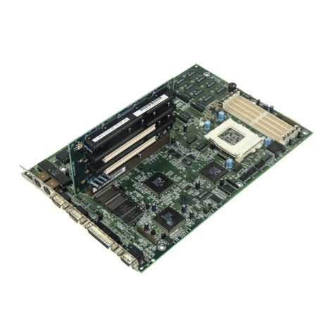
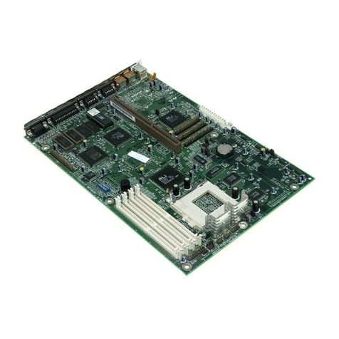
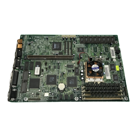
Acer Extensa 900 Series User manual

System Board
System Board 1-1
1.1 Features
This high-performance system board is designed to support the Intel
P54C and P55C CPUs running at 75/100/120/133/150/166/200 MHz.
It utilizes both the EISA and the PCI local bus architecture. Three
EISA and four PCI bus slots reside on the board to allow installation
of either master or slave devices, except for one PCI slot that
supports only slave devices.
The board has three memory banks composed of two 72-pin SIMM
sockets each that support a maximum system memory of 192 MB
using 32-MB SIMMs. The SIMM sockets support both EDO and fast-
page mode SIMMs. A second-level cache socket is available for a
256-KB or 512-KB synchronous SRAM module.
A 50-pin Fast SCSI-II interface with 10 MB/s transfer rate and a 68-
pin Wide SCSI interface that transfers at 20 MB/s (Wide SCSI) and
40 MB/s (Ultra SCSI) come with the system board to connect SCSI
devices. Standard I/O features such as two serial interfaces (COM1,
COM2), one parallel port interface, an IDE drive interface, a diskette
drive interface, and PS/2 mouse and keyboard connectors reside on
the system board.
The system board supports two optional features, the ASM Pro and
the Remote Diagnostic Management (RDM) for better server
management. These features maximize the system operating time
by minimizing the downtime.

1-2 User’s Guide
1.2 Major Components
The system board has the following major components:
•One zero-insertion force (ZIF) socket for Intel P54C or P55C
CPU
•Three memory banks (Bank 1 to Bank 3) composed of six 72-pin
SIMM sockets
•Synchronous cache module socket that supports 256 KB and
512 KB second-level cache
•Three EISA and four PCI expansion slots
•256-KB Flash ROM for system BIOS
•RTC chip that contains clock/calendar plus 128 bytes CMOS
RAM with battery backup
•50-pin Fast SCSI-II and 68-pin Wide SCSI interfaces
•Two 24-pin RDM interfaces
•IDE hard disk and diskette drive interfaces
•Onboard VRAM plus a VRAM socket for video memory upgrade
•Power connector for 200-watt switching power supply
•I/O, SCSI, VGA, memory, and ASM Pro controller chipsets
•External ports:
•PS/2-compatible keyboard port
•PS/2-compatible mouse port

System Board 1-3
1.2.1 System Board Layout
1 PS/2 keyboard connector
2 PS/2 mouse connector
3 PCI slots
4 Keyboard controller
5 EISA slots
6 Video RAM
7 Video RAM upgrade socket
8 CPU voltage regulator
9 Buzzer
10 CPU socket
11 CPU voltage regulator
12 Cache module socket
13 SIMM sockets
Figure 1-1 System Board Layout
12
4
3
5
67
9
13 10
8
11
12

1-4 User’s Guide
1.3 Jumpers and Connectors
1.3.1 Jumper and Connector Locations
Figure 1-2 shows the jumper locations on the system board. The
blackened pin on a jumper represents pin 1.
Figure 1-2 Jumper Locations
Jumpers are prefixed “JP”. Connectors are
prefixed “CN”. FA1 to FA5 are fan
connectors.
The blackened pin of a jumper represents
pin 1.

System Board 1-5
1.3.2 Jumper Settings
Table 1-1 Jumper Settings
Jumper Setting Function
CPU Voltage
JP1 1-2
2-3*VR
VRE
Cache Size
JP3 1-2*
2-3 256 KB
512 KB
BIOS Version
JP8 1-2*
2-3 Acer
Generic
Password Security
JP9 1-2
2-3* Enabled
Bypass
PC Sound Source
JP10 1-2*
2-3 Buzzer
Speaker
Front Panel Reset
JP11 1-2*
2-3 Enabled
Disabled
CPU Type
JP17, JP18, JP19 1-2
2-3* P55C CPU
P54C CPU
SCSI Selection
JP20 1-2*
2-3
4-5
PCI device ID is 11 Hex
PCI device ID is 0C Hex
Disabled
Onboard VGA
JP23 1-2*
2-3 Enabled
Disabled
*Default setting

1-6 User’s Guide
Table 1-1 Jumper Settings (continued)
Jumper Setting Function
SCSI Termination
JP24 1-2*
2-3 High-byte terminator ON
High-byte terminator OFF
Core/Bus Freq.
JP4, JP5, JP7
JP4 JP5 JP7
2-3 2-3 1-2
1-2 1-2 2-3
2-3 1-2 2-3
2-3 2-3 2-3
1-2 2-3 3-4
1-2 1-2 3-4
2-3 1-2 3-4
2-3 2-3 3-4
Bus Freq. Core Freq. Ratio
50 MHz 75 MHz 3/2
60 MHz 150 MHz 5/2
60 MHz 120 MHz 2/1
60 MHz 90 MHz 3/2
66 MHz 200 MHz 3/1
66 MHz 166 MHz 5/2
66 MHz 133 MHz 2/1
66 MHz 100 MHz 3/2

System Board 1-7
1.3.3 Connector Functions
Table 1-2 lists the different connectors on the system board and their
respective functions.
Table 1-2 Connector Functions
Connector Function
CN1 COM1
CN2 COM2
CN3 Power connector for 200-watt SPS
CN4 Power connector for 300-watt SPS
CN5 Parallel port connector
CN6 Diskette drive connector
CN7 IDE drives connector
CN8 Remote diagnostic module (RDM) connector
CN9 Remote diagnostic module (RDM) connector
CN10 Faulty-drive LED connector
CN11 Fast SCSI-II (narrow SCSI) connector
CN12 Wide SCSI connector
CN13 VGA daughter board connector
CN15 Power LED and keylock connector
CN16 Hard disk LED connector
CN17 Speaker connector
CN18 Reset/Turbo connector

1-8 User’s Guide
1.4 ESD Precautions
Always observe the following ESD (electrostatic discharge)
precautions before installing any system component:
1. Do not remove any system component from its packaging unless
you are ready to install it.
2. Wear a wrist grounding strap before handling electronic
components. Wrist grounding straps are available at most
electronic component stores.
DO NOT attempt the procedures in the
following sections unless you are confident of
your capability to perform them. Otherwise,
ask a service technician for assistance.

System Board 1-9
1.5 Installing a VGA Daughter Board
The system board comes with a video controller, a video connector,
and a VGA daughter board. These components save you the trouble
of buying a video board and save one bus slot for another expansion
board. The daughter board carries an external video port.
To install, simply plug-in the daughter board into CN13 and secure
the bracket with a screw.
Figure 1-4 Installing a VGA Daughter Board
External VGA Port
VGA Connector
(CN13)

1-10 User’s Guide
1.6 CPU Upgrade
The system board comes with a zero-insertion force (ZIF) CPU socket
for easy installation.
Follow these steps to install a Pentium CPU:
1. Pull up the socket lever.
2. Insert the CPU, making sure that the pin 1 of the CPU connects
to pin 1 of the socket.
Be careful not to bend any pins.
3. Pull down the socket lever.
Figure 1-5 Installing a Pentium CPU
STEP 1
STEP 2
STEP 3
Notched Corner
Pin 1 Indicator

System Board 1-11
4. Place the CPU heat sink and fan over the CPU.
5. Link the front heat sink hook to the holding tab on the front edge
of the CPU socket, then the rear hook to the rear holding tab.
This locks the heat sink and fan to the CPU socket.
Figure 1-6 Installing the CPU Heat Sink and Fan
To remove the heat sink and fan, simply
press the upper part of the rear hook inward.
6. Attach the CPU fan cables to the connectors on the board.
7. Change the settings of jumper JP1 for the correct CPU voltage
and jumpers JP4, JP5, and JP7 for the CPU frequency. Refer to
Table 1-1 for the jumper settings.
Holding Tab (rear)Heat Sink Hook (rear)
Heat Sink Hook (front)
Holding Tab (front)

1-12 User’s Guide
1.7 Memory Upgrade
The six 72-pin SIMM sockets onboard support both Extended Data
Output (EDO) and fast-page mode SIMMs. You may install 4-MB and
16-MB single-density as well as 8-MB, and 32-MB double-density
SIMMs for a total of 192-MB system memory. The SIMM sockets
also support 64-MB SIMMs, when available, to achieve 384-MB
system memory.
1.7.1 Rules for Adding Memory
•Use only the same type of SIMM in a given bank
•You may combine different types of SIMMs for a particular
memory configuration as long as the SIMMs in each bank are of
the same type.
•Always install SIMMs in pairs. For example, for a total memory
of 16 MB, install two 8-MB SIMMs into the sockets marked SI6
and SI5 (bank 1) or SI2 and SI1 (bank 3). You can not use a
16-MB SIMM alone for a 16-MB memory.
•Always install SIMMs starting from an inner socket. For
example, install SIMMs in socket SI6 before in socket SI5, or in
socket SI2 before socket SI1.
•Always remove SIMMs starting from an outer socket. For
example, remove SIMMs in socket SI5 before in socket SI6, or in
socket SI1 before socket SI2.

System Board 1-13
1.7.2 Memory Configurations
Table 1-3 lists the available memory configurations.
Table 1-3 Memory Configurations
Bank 1 Bank 2 Bank 3 Total
SI1 SI5 SI4 SI3 SI2 SI1 Memory
4 MB 4 MB 8 MB
8 MB 8 MB 16 MB
8 MB 8 MB 4 MB 4 MB 24 MB
8 MB 8 MB 8 MB 8 MB 32 MB
16 MB 16 MB 32 MB
16 MB 16 MB 4 MB 4 MB 40 MB
16 MB 16 MB 8 MB 8 MB 48 MB
16 MB 16 MB 8 MB 8 MB 4 MB 4 MB 56 MB
8 MB 8 MB 8 MB 8 MB 16 MB 16 MB 64 MB
4 MB 4 MB 8 MB 8 MB 32 MB 32 MB 88 MB
16 MB 16 MB 16 MB 16 MB 16 MB 16 MB 96 MB
32 MB 32 MB 8 MB 8 MB 16 MB 16 MB 112 MB
32 MB 32 MB 32 MB 32 MB 128 MB
32 MB 32 MB 32 MB 32 MB 16 MB 16 MB 160 MB
32 MB 32 MB 32 MB 32 MB 32 MB 32 MB 192 MB
The above configurations are only some of
the available memory combinations. You
can use other combinations as long as you
follow the rules for upgrading memory. See
section 1.7.1.

1-14 User’s Guide
1.7.3 Installing a SIMM
Follow these steps to install a SIMM:
1. Carefully slip a SIMM at a 45°angle into a socket making sure
that the curved edge indicating the pin 1 of the SIMM matches
pin 1 of the socket.
A SIMM fits only in one direction. If you slip
in a SIMM but would not completely fit, you
may have inserted it the wrong way.
Reverse the orientation of the SIMM.
2. Gently push the SIMM to a vertical position until the pegs of the
socket slip into the holes on the SIMM, and the holding clips lock
the SIMM into position. The SIMM should be at a 90°angle
when installed.
Figure 1-7 Installing a SIMM
Hole
Peg
Pin 1 Indicator
(curved edge)
12

System Board 1-15
1.7.4 Removing a SIMM
Follow these steps to remove a SIMM:
1. Press the holding clips on both sides of the SIMM outward to
release it.
2. Push the SIMM downward to a 45oangle.
3. Pull the SIMM out of the socket.
Figure 1-8 Removing a SIMM
1
2
3
Holding Clip

1-16 User’s Guide
1.7.5 Reconfiguring the System
Reconfigure the system after installing or removing SIMMs.
Follow these steps to reconfigure the system:
1. Reboot the system. A memory error message appears,
indicating that the total memory does not match the value stored
in CMOS.
2. Press + + during the power-on self-test (POST)
routine to run Setup. During POST, a message indicating a
wrong memory configuration appears.
3. Press twice to exit Setup and reboot the system. The
system boots with the new memory configuration.
If you operate the system with WindowsNT,
NetWare, or UnixWare, make sure to run
ECU every time you install or remove an
EISA or a non-PnP ISA card. See Chapter 3
for information on ECU.

System Board 1-17
1.8 Second-level Cache Upgrade
The system supports synchronous pipeline burst second-level cache.
The system board has an exclusive 160-pin socket for the
synchronous pipeline burst cache module. The cache module socket
supports either a 256 KB or 512 KB 3.3V cache module.
Follow these steps to install a cache module:
1. Position the cache module on top of the socket such that its
component side faces the CPU.
2. Insert the cache module carefully until the golden finger of the
module fit into place.
Figure 1-9 Installing a Synchronous Cache Module

1-18 User’s Guide
1.9 Video Memory Upgrade
Larger video memory allows you to display higher resolutions and
more colors. The system board comes with a 512-KB video memory
onboard upgradable to 1 MB.
Follow these steps to upgrade the video memory:
1. Locate the video DRAM upgrade socket labeled U44 on the
system board. See Figure 1-1.
2. Gently insert a 514260ASL (256K x 16, 70ns SOJ) chip into the
upgrade socket.
Make sure that the pin 1 indicator on the chip
matches the notched corner of the socket.
Figure 1-10 Installing a Video Memory Chip
Pin 1 Indicator
Notched Corner

System Board 1-19
1.10 SCSI Feature
The system board features a single-chip SCSI host adapter that adds
SCSI I/O capability to the system. The chipset consists of an onboard
microcontroller, bus master interface controller, and SCSI controllers.
A 50-pin Fast SCSI-II interface with 10 MB/s transfer rate and a
68-pin Wide SCSI interface that transfers at 20 MB/s (Wide SCSI)
and 40 MB/s (Ultra SCSI) are also onboard to accommodate various
SCSI devices.
1.10.1 Using the SCSI Feature
Follow these steps to use the SCSI feature:
1. Install a SCSI device in the system and connect it to the SCSI
interface on the system board. See Figure 1-1 for the location.
2. Set jumper JP20 and JP24 accordingly. Refer to Table 1-1 for
the jumper settings.
3. Enter the BIOS utility to set the corresponding SCSI parameters.
4. Enter the SCSI Setup utility and make the necessary changes.
Refer to the SCSI manual for more information.
For more information about the installation procedures under different
operating systems, read the README.XXX in the subdirectory of the
target operating system.

1-20 User’s Guide
1.11 Server Management Features
1.11.1 Remote Diagnostic Management
The Remote Diagnostic Management (RDM) is a network
management tool that utilizes modems and telephone lines to control
a host of servers from a remote station. It monitors and analyzes the
server condition, updates the BIOS settings if necessary, or reboots
the server in the event of failure and quickly return it to normal
operation. This capability to execute the RDM program from a
remote site bridges the distance barrier in fixing server problems and
reduces wasted time due to system failure.
Refer to the RDM user’s manual for more information.
1.11.2 ASM Pro
The ASM Pro is a server management tool based on the Simple
Network Management Protocol (SNMP). It detects server problems
related to the CPU thermal condition, 5V/3.3V detection, or PCI bus
utilization calculation.
This feature is designed primarily for server supervisors and
management information system (MIS) personnel to help them detect
errors or potential trouble spots in their network servers through a
single management station.
The ASM Pro consists of two major parts:
•ASM-Station - a Windows-based monitoring station that
communicates with the ASM-Agents.
•ASM-Agent(s) - the individual servers managed by the
ASM-Station.
Refer to the ASM Pro user’s manual for more information.
Other manuals for Extensa 900 Series
2
Table of contents
Other Acer Motherboard manuals

Acer
Acer V12LC User manual

Acer
Acer Ferrari 1100 Series User manual

Acer
Acer AcerPower 6500 User manual

Acer
Acer M9L Reference manual

Acer
Acer Altos 1100 Series User manual

Acer
Acer Altos 21000 Series User manual

Acer
Acer V55LA User manual

Acer
Acer V50LA User manual

Acer
Acer V65XA Installation instructions

Acer
Acer M9D User manual

Acer
Acer 700ed User manual

Acer
Acer V55LA-2 Installation instructions

Acer
Acer V60N Installation instructions

Acer
Acer V58 Installation instructions

Acer
Acer V35X User manual

Acer
Acer AcerPower 6200 User manual

Acer
Acer 9000V User manual

Acer
Acer V55 System User manual

Acer
Acer 370LXA User manual

Acer
Acer V58 User manual