Acer M1A User manual

System Board
System Board 1-1
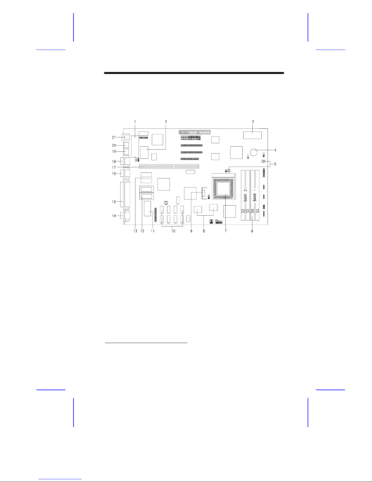
The M1A is a high-performance Pentium PCI-based system board
that supports the 64-bit Pentium microprocessor running at
75/90/100/120/133/150/166 MHz and has a 16-KB internal write-back
cache. It utilizes the Peripheral Component Interconnect (PCI) local
bus architecture. The PCI local bus maximizes the system
performance by enabling high-speed peripherals to match the speed
of the microprocessor with its 100/120/132 MB per second transfer
rate in burst mode.
The board has two memory banks composed of two 72-pin SIMM
sockets each that support a maximum system memory of 128 MB
using 32-MB SIMMs. The onboard 1-MB video memory is
upgradable to 2 MB for a higher video resolution.
The system board features a slot for the PCI/ISA slot board and two
Mode 4 PCI enhanced IDE interfaces that support up to four IDE
devices. A 50-pin Fast SCSI-II interface with 10 MB/s transfer rate
come with the system board to connect SCSI devices.
Standard I/O features such as two serial ports (COM1, COM2), one
parallel port, a diskette drive interface, and PS/2 mouse and keyboard
connectors reside on the system board.

1-2 User’s Guide
1.1 Major Features
The system board has the following major features:
•Pentium 75/90/100/120/133/150/166 MHz CPU in an SPGA 296-
pin zero-insertion force (ZIF) socket
•Two DRAM banks composed of four 72-pin SIMM sockets that
support 4/8/16/32-MB 60/70ns SIMMs
•16-KB internal cache (CPU)
•256-KB synchronous or asynchronous second-level cache
•128-KB Flash ROM for system BIOS and VGA BIOS
•EISA-type connector for the slot board that contains two PCI and
three ISA slots (for desktop housing) or three PCI and 5 ISA slots
(for minitower housing)
•Two Enhanced IDE interfaces that support up to
four IDE devices
•System clock/calendar with 128/256 bytes CMOS RAM
•External ports:
•PS/2 keyboard/mouse ports
•Two buffered high-speed serial ports
•One ECP/EPP high-speed parallel port
•Video port
•RJ-45 Ethernet connector

System Board 1-3
1.1.1 Layout
Figure 1-1 shows the locations of the system board major
components.
1 Keyboard controller
2 Real-time clock (RTC)
3 Flash ROM BIOS
4 Buzzer
5 Fan connectors
6 SIMM sockets
7 CPU socket
8 Synchronous cache (optional)
9 CPU voltage regulator
10 Asynchronous cache
11 VGA BIOS
1
12 Video upgrade sockets
13 Video RAM
14 Video port
15 Parallel port
16 COM 2
17 Slot board connector
18 COM 1
19 PS/2 mouse connector
20 PS/2 keyboard connector
21 RJ-45 connector
Figure 1-1 System Board Layout
1For SCSI models only

1-4 User’s Guide
1.1.2 Slot Board
The system board comes with a slot board already installed. The slot
board carries two PCI and three ISA bus slots for system
enhancements and future expansion.
The slot board may vary in size and layout depending on your system
housing. Figures 1-2 and 1-3 show the two kinds of slot boards.
Figure 1-2 2-PCI/3-ISA Slot Board (for desktop systems)
Figure 1-3 3-PCI/5-ISA Slot Board (for minitower systems)

System Board 1-5
1.2 Jumpers and Connectors
1.2.1 Jumper and Connector Locations
Figure 1-4 shows the jumper and connector locations on the system
board.
Figure 1-4 System Board Jumper and Connector Locations
Jumpers are prefixed “JP”. Connectors are
prefixed “CN”.
The blackened pin of a jumper represents
pin 1.

1-6 User’s Guide
1.2.2 Jumper Settings
Table 1-1 lists the system board jumpers with their corresponding
settings and functions.
Table 1-1 System Board Jumper Settings
Jumper Setting Function
BIOS Type
JP1 1-2
2-3 For models with Acer BIOS
For models with OEM BIOS
Password Security
JP2 1-2
2-3 Enable password
Disable password
CPU Bus Frequency
JP5 Open
1-2
2-3
50 MHz (Pentium 75 MHz)
60 MHz (Pentium 90/120/150 MHz)
66 MHz (Pentium 100/133/166
MHz)
CPU Voltage
JP7 1-2
2-3 VR (3.3V ± 5% - 0%)
VRE (3.45V ~ 3.6V)
Reserved
JP9 2-3* Fixed setting. Do not reconfigure.
Reserved
JP14 Open* Leave open. Do not reconfigure.

System Board 1-7
Table 1-1 System Board Jumper Settings (continued)
Jumper Setting Function
CPU Type
JX1, JP8
JX1, JP8
JP10
JP11
JP12
JP13
2-3, 1-2
2-3, 2-3
1-2, 1-2
1-2, 2-3
Intel P54C M1 K5
C/B=3/1
C/B=5/2
C/B=3/2 C/B=3/1 C/B=3/2, 3/3
C/B=2/1 C/B=2/1 C/B=1/1
On Off On
On Off On
On Off Off
On Off On
1.2.3 Connector Functions
Table 1-2 lists the different connectors on the system board and their
respective functions.
Table 1-2 Connector Functions
Connector Function
CN4 Attachment Unit Interface (AUI)
CN5 Feature connector
CN6 Diskette drive connector
CN7 Enhanced IDE 2
CN8 Enhanced IDE 1
CN9 Power connector
CN10 SCSI connector
CN11 Power LED connector
CN12 Multifunction connector

1-8 User’s Guide
Table 1-2 Connector Functions (continued)
Connector Function
CN13 HDD LED connector
CN14 Speaker connector
CN15 Multifucntion connector
CN16 Buzzer (pins 1-2)
Speaker (pins 2-3)
1.3 ESD Precautions
Always observe the following electrostatic discharge (ESD)
precautions before installing a system component:
1. Do not remove a component from its antistatic packaging until
you are ready to install it.
2. Wear a wrist grounding strap before handling electronic
components. Wrist grounding straps are available at most
electronic component stores.
Do not attempt the procedures described in
the following sections unless you are a
qualified technician.

System Board 1-9
1.4 Memory Upgrade
The system board comes with four 72-pin SIMM sockets that support
4-MB and 16-MB single-density SIMMs as well as 8-MB and 32-MB
double-density SIMMs. When using 32-MB SIMMs, the sockets
support a maximum system memory of 128 MB. Table 1-3 lists the
possible memory configurations.
1.4.1 Rules for Adding Memory
•Use only one type of SIMM in a given bank.
•You may combine different types of SIMMs for a memory
configuration as long as the SIMMs in each bank are of the same
type.
•Always install SIMMs in pairs. For example, for a total memory
of 8 MB, install two 4-MB SIMMs into the sockets marked S5 and
S4 (bank 0) or S3 and S2 (bank 1). You can not use an 8-MB
SIMM alone for an 8-MB memory.

1-10 User’s Guide
1.4.2 Memory Configurations
Table 1-3 Memory Configurations
Bank 0 Bank 1 Total
S5 S4 S3 S2 Memory
4 MB 4 MB 8 MB
4 MB 4 MB 8 MB
8 MB 8 MB 16 MB
8 MB 8 MB 16 MB
4 MB 4 MB 4 MB 4 MB 16 MB
4 MB 4 MB 8 MB 8 MB 24 MB
8 MB 8 MB 4 MB 4 MB 24 MB
8 MB 8 MB 8 MB 8 MB 32 MB
16 MB 16 MB 32 MB
16 MB 16 MB 32 MB
4 MB 4 MB 16 MB 16 MB 40 MB
16 MB 16 MB 4 MB 4 MB 40 MB
8 MB 8 MB 16 MB 16 MB 48 MB
16 MB 16 MB 8 MB 8 MB 48 MB
16 MB 16 MB 16 MB 16 MB 64 MB
32 MB 32 MB 64 MB
32 MB 32 MB 64 MB
4 MB 4 MB 32 MB 32 MB 72 MB
32 MB 32 MB 4 MB 4 MB 72 MB
8 MB 8 MB 32 MB 32 MB 80 MB
32 MB 32 MB 8 MB 8 MB 80 MB
16 MB 16 MB 32 MB 32 MB 96 MB
32 MB 32 MB 16 MB 16 MB 96 MB
32 MB 32 MB 32 MB 32 MB 128 MB

System Board 1-11
1.4.3 Installing a SIMM
Follow these steps to install a SIMM:
1. Slip a SIMM at a 45°angle with the component side facing down
into the socket labeled S5.
Be careful when inserting SIMMs to avoid
damaging the SIMM or the socket.
2. Gently press the SIMM up until the pegs of the socket fit into the
holes on the SIMM and the holding clips lock the SIMM into
position. The SIMM should be at a 90°angle when installed.
Figure 1-5 Installing a SIMM
Hole
Peg
Clip

1-12 User’s Guide
1.4.4 Removing a SIMM
Follow these steps to remove a SIMM:
1. Press the holding clips on both sides of the SIMM outward to
release it.
2. Move the SIMM to a 45°angle.
3. Pull the SIMM out of the socket.
Figure 1-6 Removing a SIMM
1
2
3

System Board 1-13
1.4.5 Reconfiguring the System
You must enter Setup after installing or removing SIMMs to
reconfigure the system.
Follow these steps to reconfigure the system:
1. Turn the system on. A memory error message appears,
indicating that the total memory does not match the value stored
in CMOS.
2. Press
+
+
to enter Setup. A warning message
appears indicating an incorrect memory configuration.
3. Press
twice to exit and reboot the system.
The system boots with the new memory configuration.
1.5 IDE Hard Disk Support
The system board supports four IDE hard disks, or any other IDE
devices, through the two onboard Enhanced IDE interfaces. See
Figure 1-3 for the location of the interfaces.
Follow the instructions in the housing installation manual on how to
install a hard disk in the system. Connect the cables according to the
IDE hard disk configuration in Table 1-4.
Table 1-4 IDE Hard Disk Configuration
IDE Connector Master Slave
Channel 1 Hard disk 0 Hard disk 1
Channel 2 Hard disk 2 Hard disk 3

1-14 User’s Guide
1.6 CPU Installation
The system board comes with a zero-insertion force (ZIF) CPU socket
for easy installation.
Follow these steps to install a Pentium CPU:
1. Lift up the socket lever.
2. Insert the CPU into the socket. Make sure that the notched
corner of the CPU matches the pin 1 indicator on the socket.
Be careful not to bend any pins.
3. Push down the socket lever.
Figure 1-7 Installing a Pentium CPU
4. Set jumpers JP3 according to the CPU speed, and JX1, JP8,
JP10, JP11, JP12, and JP13 for the correct CPU type. Refer to
Table 1-1 for the jumper settings.
STEP 1 STEP 2
STEP 3
Notched Corner
Pin 1 Indicator

System Board 1-15
1.7 Video Memory Upgrade
Larger video memory allows you to display higher resolutions and
more colors. The system board comes with a 1-MB video memory
onboard upgradable to 2 MB.
Follow these steps to upgrade the video memory:
1. Locate the video DRAM upgrade sockets labeled U10 and U11
on the system board. See Figure 1-1.
2. Gently insert a video chip into each of the upgrade sockets.
Make sure that the pin 1 indicator on the chip
matches the notched corner of the socket.
Figure 1-8 Installing a Video Memory Chip
Pin 1 Indicator
Notched Corner

1-16 User’s Guide
1.8 Error Messages
Do not continue using the computer if you receive an error message
of any type. Note the message and take corrective action. This
section explains the different types of error messages and
corresponding corrective measures.
There are two general types of error messages:
•Software
•System
1.8.1 Software Error Messages
Software error messages are returned by your operating system or
application. These messages typically occur after you boot the
operating system or when you run your applications. If you receive
this type of message, consult your application or operating system
manual for help.
1.8.2 System Error Messages
A system error message indicates a problem with the computer itself.
A message of this type normally appears during the power-on self-
test, before the operating system prompt appears.
Table 1-5 lists the system error messages.

System Board 1-17
Table 1-5 System Error Messages
Message Action
CMOS Battery Error Replace the RTC chip or
contact your dealer.
CMOS Checksum Error Check the RTC chip and the
necessary jumper. If the
battery is still good, run
Setup.
Display Card Mismatch Run Setup.
Diskette Drive Controller
Error or Not Installed Check and connect the
control cable to the diskette
controller.
Diskette Drive Error Diskette may be defective. If
not, replace the diskette drive.
Diskette Drive A Type
Mismatch Run Setup and select the
proper drive type.
Diskette Drive B Type
Mismatch Run Setup and select the
proper drive type.
Equipment Configuration
Error Modify the memory
configuration to agree with
one of the options in Table
1-3.
Hard disk Controller Error Run Setup.
Hard disk 0 Error Check all cable connections.
Replace hard disk.
Hard disk 1 Error Check all cable connections.
Replace hard disk.
Keyboard Error or No
Keyboard Connected Check and connect the
keyboard to the system unit.
Keyboard Interface Error Replace the keyboard or
contact your dealer.

1-18 User’s Guide
Table 1-5 System Error Messages (continued)
Message Action
Memory Error at:
MMMM:SSSS:OOO
(W:XXXX, R:YYYY)
where:
M: MB, S: Segment,
O: Offset, X/Y: write/read
pattern
Check SIMMs on the system
board. Contact your dealer.
Memory Size Mismatch
CPU Clock Mismatch Run Setup. Check if the
values shown in the memory
parameters are correct. If
correct, exit Setup and reboot
the system. If the error
message reappears, seek
technical assistance.
Onboard Serial Port 1
Conflict Run Setup and disable the
port.
Onboard Serial Port 2
Conflict Run Setup and disable the
port.
Onboard Parallel Port
Conflict Run Setup and disable the
port.
Pointing Device Error Check and connect pointing
device.
Pointing Device Interface
Error Replace the pointing device or
contact your dealer.
Press
key to continue or
+
+
for Setup Press
or
+
+
to enter
Setup.
Real Time Clock Error Check the RTC chip. If it is
still good, run Setup. If not,
replace the RTC chip.

System Board 1-19
1.8.3 Correcting Error Conditions
As a general rule, if an error message says "Press F1 to continue," it
is caused by a configuration problem, which can be easily corrected.
An equipment malfunction is more likely to cause a fatal error, i.e., an
error that causes complete system failure.
Here are some corrective measures for error conditions:
1. Run Setup. You must know the correct configuration values for
your system before you enter Setup, which is why you should
write them down when the system is correctly configured. An
incorrect configuration is a major cause of power-on error
messages, especially for a new system.
2. Remove the system unit cover. Check that the jumpers on the
system board and any expansion boards are set correctly.
3. If you cannot access a new disk, it may be because your disk is
not properly formatted. Format the disk first using the FDISK
and FORMAT commands.
4. Check that all connectors and boards are securely plugged in.
If you go through the corrective steps above and still receive an error
message, the cause may be an equipment malfunction.
If you are sure that your configuration values are correct and your
battery is in good condition, the problem may lie in a damaged or
defective chip.
In either case, contact an authorized service center for assistance.
Table of contents
Other Acer Motherboard manuals