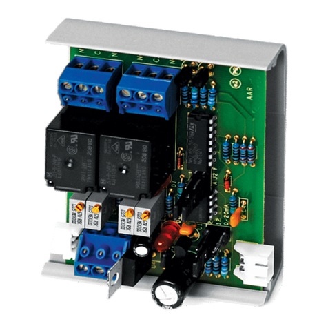
aci ACCESS series Installation instructions

Automation Components, Inc.
2305 Pleasant View Road | Middleton, WI 53562
Phone: 1-888-967-5224 | Website: workaci.com
Page 1
Version: 3.0
I0000600
GENERAL INFORMATION
The DMUX-4 is a selectable output controller
designed to expand the output capacity of an
energy management or process controller. The
DMUX-4S has up to four output relays. Common (C),
Normally Open (NO), and Normally Closed (NC)
connections are available for each output. Three
position On/O/Auto jumpers are standard and
allow manual override at the DMUX-4. It converts a
relay, transistor or Triac input signal to operate an
appropriate relay output based on the duration of
the signal. The relay output has an LED indicator for
a visual verication of operation. There are also LED
indicators to show the presence of power to the
DMUX-4 and the input pulse. This program oers
dierent modes of operation using the Solidyne™
fast pulse input. This device is DIP switch selectable
for sequencing, or reverse sequencing or Rooftop
Unit 4 relay control.
MOUNTING INSTRUCTIONS
Ground yourself to discharge static electricity before touching any electronic equipment, as some
components are static sensitive. The interface device can be mounted in any position. If circuit
board slides out of snap track, a non-conductive “stop”may be required. Use only ngers to remove
board from snap track. Slide out of snap track or push up against side of snap track and lift that
side of the circuit board to remove. Do not flex board or use tools.
WIRING INSTRUCTIONS
PRECAUTIONS
• Remove power before wiring. Never connect or disconnect wiring with power applied.
• When using a shielded cable, ground the shield only at the controller end. Grounding both
ends can cause a ground loop.
• It is recommended you use an isolated UL-listed class 2 transformer when powering the unit
with 24 VAC. Failure to wire the devices with the correct polarity when sharing transformers may
result in damage to any device powered by the shared transformer.
• If the 24 VDC or 24VAC power is shared with devices that have coils such as relays, solenoids, or
other inductors, each coil must have an MOV, DC/AC Transorb, Transient Voltage Suppressor (ACI
Part: 142583), or diode placed across the coil or inductor. The cathode, or banded side of the DC
Transorb or diode, connects to the positive side of the power supply. Without these snubbers,
coils produce very large voltage spikes when de-energizing that can cause malfunction or
destruction of electronic circuits.
• All wiring must comply with all local and National Electric Codes.
FIGURE 1: DIMENSIONS
INTERFACE SERIES
Installation & Operation Instructions
DMUX-4
Phone: 1-888-967-5224
Website: workaci.com
3.22"
(81.78mm)
4.82" (122.42mm)
L10
J10
J9
L9
J1
J4J2 J3
L2
D2
K2
L1
D1
K1
L4
D4
K4
L3
D3
K3
= AUTO
A
= OFF
-
= ON
O
PULSE
TRIAC
NORM
PWR
+
AC
-
DC
IN
+ -
M 1
POWER
D
E
3
O
2
C2
NC
NO
C1
NO
NC
A
O
A
O
NO
NC
C4 C3
NC
NO
A
O
A
O
3
3.25"
(82.55mm)
4.69" (119.13mm)
0.70”
(17.78mm)
This program oers dierent modes of operation using the Solidyne fast pulse input. Input ranges are
given in percentages from 4-96% and also milliseconds from 10-230ms. Relay action does not occur until
the M977 receives 10 identical pulse cycles of the same range. Any input range that is less than 4%, or after
5 seconds with NO input pulse, will command an ALL OFF relay action.
Apply power: the “POWER” LED should light. Close the pulse input relay contacts: the “PULSE” LED should
light indicating that the M977 is receiving the timing signal. Further test the M977 operation by comparing
the operation of output relays with respective input pulse. The LED for each relay will turn on when the
respective relay is activated. No action on longer pulses.
SEQUENTIAL RELAY CONTROL
The program has to see 10 identical pulse cycles before a sequencing relay action can occur.
DIP SWITCH selections: OFF- 1, 2, 3

GENERAL INFORMATION
The DMUX-4 is a selectable output controller
designed to expand the output capacity of an
energy management or process controller. The
DMUX-4S has up to four output relays. Common (C),
Normally Open (NO), and Normally Closed (NC)
connections are available for each output. Three
position On/O/Auto jumpers are standard and
allow manual override at the DMUX-4. It converts a
relay, transistor or Triac input signal to operate an
appropriate relay output based on the duration of
the signal. The relay output has an LED indicator for
a visual verication of operation. There are also LED
indicators to show the presence of power to the
DMUX-4 and the input pulse. This program oers
dierent modes of operation using the Solidyne™
fast pulse input. This device is DIP switch selectable
for sequencing, or reverse sequencing or Rooftop
Unit 4 relay control.
MOUNTING INSTRUCTIONS
Ground yourself to discharge static electricity before touching any electronic equipment, as some
components are static sensitive. The interface device can be mounted in any position. If circuit
board slides out of snap track, a non-conductive “stop”may be required. Use only ngers to remove
board from snap track. Slide out of snap track or push up against side of snap track and lift that
side of the circuit board to remove. Do not flex board or use tools.
WIRING INSTRUCTIONS
PRECAUTIONS
• Remove power before wiring. Never connect or disconnect wiring with power applied.
• When using a shielded cable, ground the shield only at the controller end. Grounding both
ends can cause a ground loop.
• It is recommended you use an isolated UL-listed class 2 transformer when powering the unit
with 24 VAC. Failure to wire the devices with the correct polarity when sharing transformers may
result in damage to any device powered by the shared transformer.
• If the 24 VDC or 24VAC power is shared with devices that have coils such as relays, solenoids, or
other inductors, each coil must have an MOV, DC/AC Transorb, Transient Voltage Suppressor (ACI
Part: 142583), or diode placed across the coil or inductor. The cathode, or banded side of the DC
Transorb or diode, connects to the positive side of the power supply. Without these snubbers,
coils produce very large voltage spikes when de-energizing that can cause malfunction or
destruction of electronic circuits.
• All wiring must comply with all local and National Electric Codes.
FIGURE 2: WIRING
Automation Components, Inc.
2305 Pleasant View Road | Middleton, WI 53562
Phone: 1-888-967-5224 | Website: workaci.com
Page 2
Version: 3.0
I0000600
24 VAC/VDC
Power Supply
This program oers dierent modes of operation using the Solidyne fast pulse input. Input ranges are
given in percentages from 4-96% and also milliseconds from 10-230ms. Relay action does not occur until
the M977 receives 10 identical pulse cycles of the same range. Any input range that is less than 4%, or after
5 seconds with NO input pulse, will command an ALL OFF relay action.
Apply power: the “POWER” LED should light. Close the pulse input relay contacts: the “PULSE” LED should
light indicating that the M977 is receiving the timing signal. Further test the M977 operation by comparing
the operation of output relays with respective input pulse. The LED for each relay will turn on when the
respective relay is activated. No action on longer pulses.
SEQUENTIAL RELAY CONTROL
The program has to see 10 identical pulse cycles before a sequencing relay action can occur.
DIP SWITCH selections: OFF- 1, 2, 3
Mode Switch
See Figure A
(+)
(-)
00-19%
20-39%
40-59%
60-79%
80-96%
ALL OFF
1
1,2
1,2,3
1,2,3,4
RANGE % RELAYS

Automation Components, Inc.
2305 Pleasant View Road | Middleton, WI 53562
Phone: 1-888-967-5224 | Website: workaci.com
Page 3
Version: 3.0
I0000600
REVERSE SEQUENCE RELAY CONTROL
The program has to see 10 identical pulse cycles before a sequencing relay action can occur. As
the PWM value rises, relays will come ON in sequence until reaching the 50% deadband range,
providing an ALL OFF condition. On a PWM increase to 96%, de-energizing of the relays will occur
in the reverse sequence.
DIP SWITCH selections: ON - 2 OFF - 1,3
Falling %
4%
12-8%
20-16%
28-24%
40-32%
56-44%
64-60%
72-68%
80-76%
96-84%
Relays On
ALL OFF
1
1,2
1,2,3
1,2,3,4
ALL OFF
4
4,3
4,3,2
4,3,2,1
Relays On
ALL OFF
1
1,2
1,2,3
1,2,3,4
ALL OFF
4
4,3
4,3,2
4,3,2,1
Rising %
4-8%
12-16%
20-24%
28-32%
36-40%
44-60%
64-68%
72-76%
80-84%
88-96%
ROOFTOP UNIT CONTROL
The program has to see 10 identical pulse cycles before a sequencing relay action can occur. This mode of
operation is for 4-relay control of Rooftop Units, and includes a 50% deadband. With dip switch one (1) in
the ON position, a pulse to the 50% deadband range provides a fan override of eight minutes, and then
OFF. A change in pulsing from the deadband setting will activate relays
accordingly.
Note: <4%, or no pulse=ALL OFF
DIP SWITCH selections: OFF- 1 ON -2,3
EXAMPLE:
Relay number RTU Control Function
1 Cool 1 (C1)
2 Cool 2 (C2)
3 Heat 1 (H1)
4 Fan (F)
% RANGE
4-19
20-31
32-43
44-55
56-67
68-96
RELAY ACTION
4,2,1
4,1
4
ALL OFF
4
4,3
CONTROLS STAGES
F,C1,C2
F,C1
F
DEADBAND
F
F,H1
PULSE TIMING (ms)
10-40
50-70
80-100
110-130
140-160
170-240

WARRANTY
The DMUX Series are covered by ACI’s Two (2) Year Limited Warranty, which is located in the front of ACI’S
SENSORS & TRANSMITTERS CATALOG or can be found on ACI’s website: www.workaci.com.
W.E.E.E. DIRECTIVE
At the end of their useful life the packaging and product should be disposed of via a suitable recycling
centre. Do not dispose of with household waste. Do not burn.
FIGURE 3: SWITCH SETTINGS
Automation Components, Inc.
2305 Pleasant View Road | Middleton, WI 53562
Phone: 1-888-967-5224 | Website: workaci.com
Page 4
Version: 3.0
I0000600
PRODUCT SPECIFICATIONS
24 VAC or 24VDC, (+/- 10%), 50/60 Hz
260 mA maximum
Relay Contact Closure, Transistor or Triac (jumper selectable)
5 to 24 volts AC or DC, 20 mA maximum
Solidyne™ Fast 4 Pulse
10 milliseconds minimum
Form “C” Relays
2A maximum @ 24 VDC
100,000 operations minimum
1,000,000 operations
4 N.O. and N.C. contacts
Three-position (ON/OFF/AUTO)
45° Captive screw Terminal Blocks
12 (3.31 mm) to 22 AWG (0.33 mm)
0.5 Nm (Minimum); 0.6 Nm (Maximum)
35 to 120°F (1.7 to 48.9°C)
10 to 95% non-condensing
-20 to 150°F (-28.9 to 65.5°C)
SENSOR NON-SPECIFIC INFORMATION
Supply Voltage:
Supply Current:
Input Pulse Source:
Input Pulse Trigger Level:
Input Pulse Timing:
Off Time Between Pulses:
Digital Output Type:
Relay Contact Rating:
Relay Electrical Life:
Relay Mechanical Life:
Output Relay:
Relay Override Jumpers:
Connections:
Wire Size:
Terminal Block Torque Rating:
Operating Temperature Range:
Operating Humidity Range:
Storage Temperature:
Other manuals for ACCESS series
16
This manual suits for next models
1
Other aci Relay manuals
Popular Relay manuals by other brands
Omron
Omron SYSMAC W398-E1-1 Operation manual

Hella
Hella 3099 Operation and installation instructions
Konica Minolta
Konica Minolta RU-515 installation manual
Schweitzer Engineering Laboratories
Schweitzer Engineering Laboratories SEL-387-0 instruction manual

Pilz
Pilz S1SW P operating instructions
ABB
ABB TA 200 DU V1000 operating instructions
