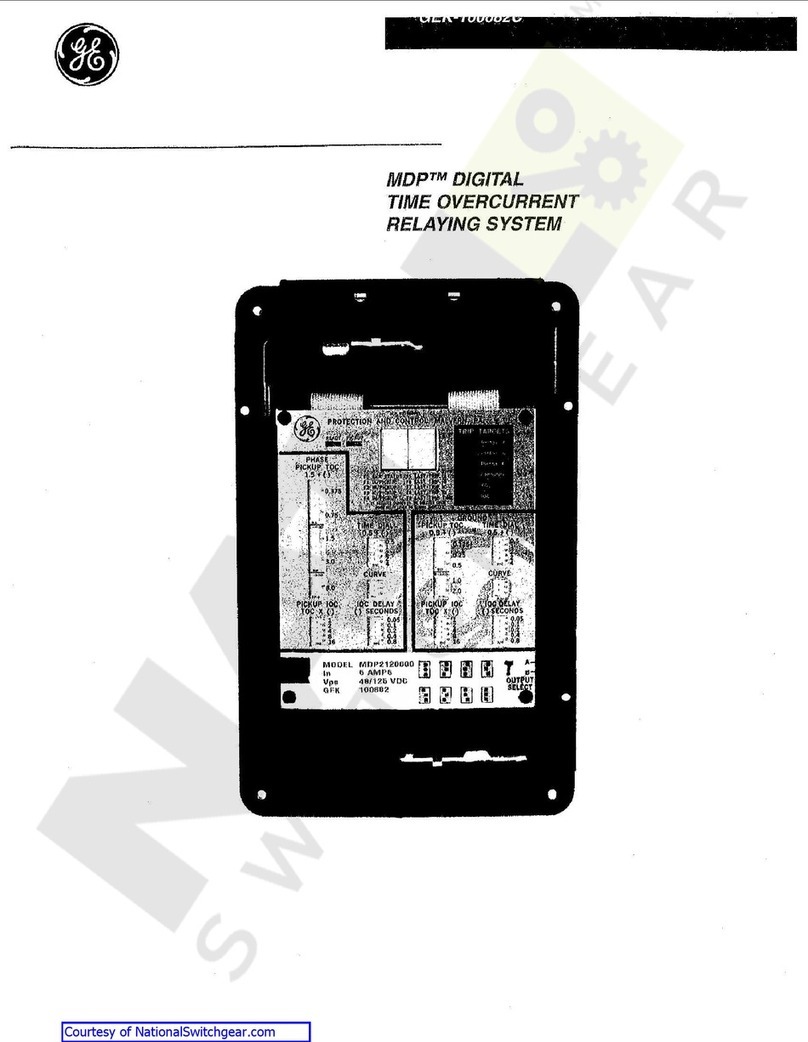
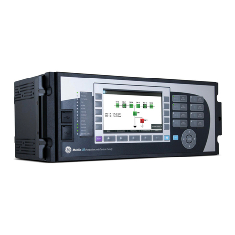
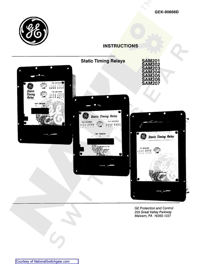
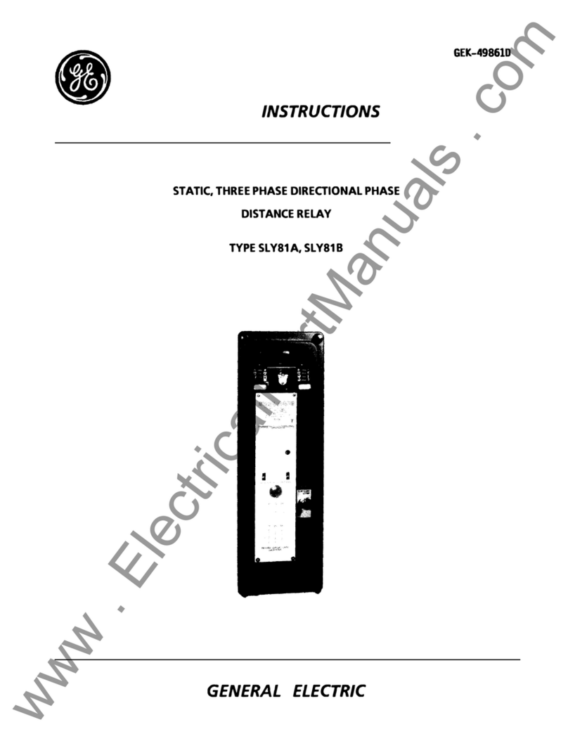
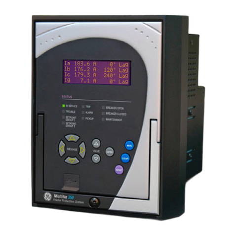
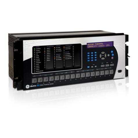
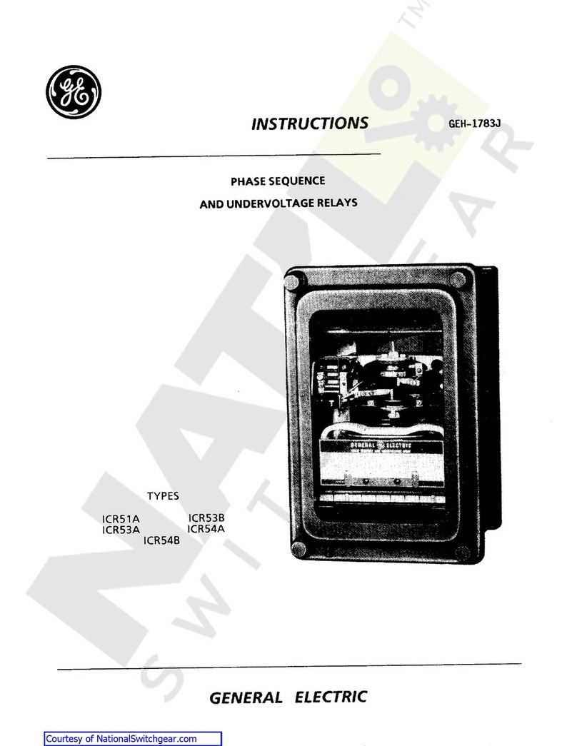
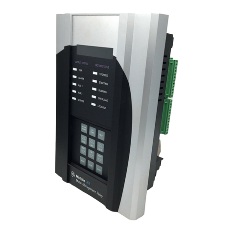
GE DGP Series User manual

DGP
Digital Generator Protection Relay™
Instruction Manual
DGP Revisions:V210.12000P
V210.10000F
V211.32000J
V210.22000D
Manual P/N: GEK-100666D
Copyright © 2000 GE Power Management
GE Power Management
215 Anderson Avenue,Markham, Ontario
Canada L6E1B3
Tel:(905) 294-6222Fax:(905) 294-8512
Internet: http://www.GEindustrial.com/pm
All relays must be powered up at least once peryear
to avoid deterioration of electrolytic capacitors and
subsequent relay failure.
NOTE
Manufactured under an
ISO9002 Registered system.
g
GEPowerManagement


These instructions do not purport to cover all details or variations in equipment
nor provide for every possible contin
g
ency to be met in connection with
installation, operation, or maintenance. Should further information be desired
or should particular problems arise which are not covered sufficiently for the
purchaser’s purpose, the matter should be referred to the General Electric
Company.
To the extent required the products described herein meet applicable ANSI,
IEEE, and NEMA standards; but no such assurance is
g
iven with respect to
local codes and ordinances because they vary
g
reatly.


GE Power Management DGP Digital Generator Protection System
i
TABLE OF CONTENTS
1. PRODUCT DESCRIPTION 1.1 GETTING STARTED
1.1.1 UNPACKING THE RELAY......................................................................... 1-1
1.1.2 ORDER CODES & SELECTION GUIDE...................................................1-2
1.1.3 SPECIAL MODELS.................................................................................... 1-3
DGP***AAA-0101 and DGP***AAA-0102....................................................... 1-3
DGP***ABA-0005 ........................................................................................... 1-3
1.1.4 DEC 1000 CONTACT EXPANSION UNIT................................................. 1-3
1.2 INTRODUCTION
1.2.1 GENERAL.................................................................................................. 1-4
1.2.2 APPLICATION........................................................................................... 1-4
1.3 PROTECTION FEATURES
1.3.1 DESCRIPTION .......................................................................................... 1-6
1.3.2 STATOR DIFFERENTIAL (87G)................................................................ 1-7
1.3.3 CURRENT UNBALANCE (46T)................................................................. 1-7
1.3.4 LOSS OF EXCITATION (40) ..................................................................... 1-7
1.3.5 ANTI-MOTORING (32) .............................................................................. 1-8
1.3.6 TIME OVERCURRENT WITH VOLTAGE RESTRAINT 51V.....................1-8
1.3.7 STATOR GROUND (64G/27TN) ............................................................... 1-8
1.3.8 GROUND OVERCURRENT (51GN) ......................................................... 1-9
1.3.9 OVEREXCITATION (24)............................................................................ 1-9
1.3.10 OVERVOLTAGE (59) .............................................................................. 1-10
1.3.11 UNDERVOLTAGE (27)............................................................................ 1-10
1.3.12 OVER AND UNDERFREQUENCY (81) ..................................................1-10
1.3.13 VOLTAGE TRANSFORMER FUSE FAILURE (VTFF)............................1-10
1.3.14 ACCIDENTAL ENERGIZATION (AE)...................................................... 1-11
1.4 OTHER FEATURES
1.4.1 INPUTS.................................................................................................... 1-17
1.4.2 OUTPUT RELAYS................................................................................... 1-17
1.4.3 START-UP SELF-TESTS........................................................................ 1-18
1.4.4 RUN-TIME SELF-TESTS......................................................................... 1-18
1.4.5 ADAPTIVE SAMPLING FREQUENCY.................................................... 1-19
1.4.6 TRIP CIRCUIT MONITOR....................................................................... 1-19
1.4.7 SEQUENCE OF EVENTS.......................................................................1-19
1.4.8 TIME SYNCHRONIZATION..................................................................... 1-20
1.4.9 FAULT REPORT & OSCILLOGRAPHY DATA........................................ 1-21
1.4.10 LOCAL MAN-MACHINE INTERFACE..................................................... 1-21
1.4.11 LOCAL PRINTER .................................................................................... 1-21
1.4.12 REMOTE COMMUNICATIONS............................................................... 1-22
1.4.13 REMOTE CONTROL............................................................................... 1-22
1.4.14 PASSWORD PROTECTION ................................................................... 1-22
1.4.15 REMOTE COMMUNICATIONS – MODBUS PROTOCOL...................... 1-22
1.5 ELEMENTARY DIAGRAMS
2. CALCULATION OF
SETTINGS 2.1 GENERAL
2.1.1 DESCRIPTION .......................................................................................... 2-1
2.2 CONFIGURATION SETTINGS
2.2.1 DESCRIPTION ........................................................................................ 2-10
101: UNITID – UNIT ID NUMBER ................................................................ 2-10
102: SYSFREQ – SYSTEM FREQUENCY.................................................. 2-10
103: SEL TVM – SELECT TRIP VOLTAGE MONITORING......................... 2-10
104: SEL TCM – SELECT TRIP CURRENT MONITORING........................ 2-10
105: SELPRIM – SELECT PRIMARY/SECONDARY UNITS....................... 2-10
106: CT RATIO – CURRENT TRANSFORMER RATIO...............................2-10

ii
DGP Digital Generator Protection System GE Power Management
TABLE OF CONTENTS
107: VT RATIO – VOLTAGE TRANSFORMER RATIO................................ 2-10
108: COMMPORT – COMMUNICATIONS PORT........................................ 2-11
109: PHASE – PHASE DESIGNATION........................................................ 2-11
110: TIMESYNC – TIME SYNCHRONIZATION SOURCE...........................2-11
111: NUM FLTS – NUMBER OF FAULT EVENTS.......................................2-11
112: PREFLT – PREFAULT CYCLES..........................................................2-12
113: OSC TRIG – EXTERNAL OSCILLOGRAPHY TRIGGER ....................2-12
114: NOM VOLT – NOMINAL VOLTAGE.....................................................2-12
115: RATEDCUR – RATED CURRENT.......................................................2-12
116: VT CONN – VOLTAGE TRANSFORMER CONNECTION...................2-12
117: NCTRATIO – NEUTRAL CURRENT TRANSFORMER RATIO ...........2-12
2.2.2 EXAMPLE CONFIGURATION SETTINGS.............................................. 2-12
2.3 PROTECTION FUNCTION SETTINGS
2.3.1 TRIP AND ALARM OUTPUT RELAYS.................................................... 2-13
2.3.2 STATOR DIFFERENTIAL 87G................................................................ 2-13
2.3.3 CURRENT UNBALANCE ALARM 46A.................................................... 2-18
2.3.4 CURRENT UNBALANCE TRIP 46T........................................................2-18
2.3.5 LOSS OF EXCITATION 40, 40-1, 40-2 ...................................................2-20
2.3.6 ANTI-MOTORING (REVERSE POWER)................................................. 2-21
2.3.7 OVERCURRENT WITH VOLTAGE RESTRAINT (51V).......................... 2-22
2.3.8 STATOR GROUND FAULT 64G-1..........................................................2-28
2.3.9 STATOR GROUND FAULT 64G-2..........................................................2-28
2.3.10 STATOR GROUND FAULT 27TN ........................................................... 2-28
2.3.11 OVEREXCITATION ALARM (VOLTS/HERTZ: 24A) ............................... 2-29
2.3.12 OVEREXCITATION TRIP (VOLTS/HERTZ: 24T).................................... 2-29
2.3.13 OVERVOLTAGE 59.................................................................................2-34
2.3.14 UNDERVOLTAGE CUTOFF OF 81......................................................... 2-36
2.3.15 UNDERFREQUENCY 81-U..................................................................... 2-36
2.3.16 OVERFREQUENCY 81-O ....................................................................... 2-36
2.3.17 DIGITAL INPUT DI...................................................................................2-36
2.3.18 VOLTAGE TRANSFORMER FUSE FAILURE VTFF ..............................2-37
2.3.19 ACCIDENTAL ENERGIZATION AE ........................................................ 2-37
2.3.20 GROUND OVERCURRENT 51GN..........................................................2-38
2.3.21 UNDERVOLTAGE 27 .............................................................................. 2-38
2.4 COMMISSIONING
2.4.1 DGP***AAA SETTINGS TABLE ..............................................................2-41
2.4.2 DGP***ABA SETTINGS TABLE ..............................................................2-46
2.4.3 DGP***ACA SETTINGS TABLE .............................................................. 2-51
3. HARDWARE
DESCRIPTION 3.1 CASE ASSEMBLY
3.1.1 WARNING.................................................................................................. 3-1
3.1.2 CONSTRUCTION...................................................................................... 3-1
3.1.3 ELECTRICAL CONNECTIONS & INTERNAL WIRING............................. 3-1
3.1.4 IDENTIFICATION ...................................................................................... 3-1
3.2 CIRCUIT BOARD MODULES
3.2.1 WARNING.................................................................................................. 3-4
3.2.2 BASIC CONSTRUCTION .......................................................................... 3-4
3.2.3 IDENTIFICATION ...................................................................................... 3-4
3.3 XTM TEST PLUGS
3.3.1 DESCRIPTION .......................................................................................... 3-6
3.3.2 TERMINAL DESIGNATION....................................................................... 3-6
3.3.3 XTM TEST-CIRCUIT CONNECTIONS...................................................... 3-6
3.3.4 TEST PLUG INSERTION .......................................................................... 3-6

GE Power Management DGP Digital Generator Protection System
iii
TABLE OF CONTENTS
3.4 INSTALLATION
3.4.1 RECEIVING, HANDLING, & STORAGE.................................................... 3-7
3.4.2 ENVIRONMENT ........................................................................................ 3-7
3.4.3 MOUNTING ............................................................................................... 3-7
3.4.4 EXTERNAL CONNECTIONS .................................................................... 3-7
3.4.5 EXTERNAL CONNECTIONS TEST.......................................................... 3-7
3.4.6 SURGE GROUND CONNECTIONS.......................................................... 3-7
4. ACCEPTANCE TESTS 4.1 INTRODUCTION
4.1.1 WARNING.................................................................................................. 4-1
4.1.2 GENERAL.................................................................................................. 4-1
a GENERAL TESTS..................................................................................... 4-1
b PROTECTION TESTS............................................................................... 4-1
4.2 TEST PREPARATION
4.2.1 TEST EQUIPMENT ................................................................................... 4-2
4.2.2 DRAWINGS & REFERENCES..................................................................4-2
a DRAWINGS............................................................................................... 4-2
b REFERENCES .......................................................................................... 4-2
4.2.3 EQUIPMENT GROUNDING ...................................................................... 4-2
4.2.4 REQUIRED SETTINGS............................................................................. 4-2
4.3 GENERAL INSTRUCTIONS
4.3.1 PROCEDURE............................................................................................ 4-3
4.3.2 SETTING CHANGES................................................................................. 4-3
4.3.3 ENTERING THE TEST MODE .................................................................. 4-4
4.3.4 EXITING THE TEST MODE ...................................................................... 4-4
4.4 USING GE-LINK
4.4.1 DESCRIPTION .......................................................................................... 4-5
4.4.2 HARDWARE SETUP................................................................................. 4-5
4.4.3 SOFTWARE SETUP.................................................................................. 4-5
a LOAD & START GE-LINK..........................................................................4-5
b SET UP A NEW TEST UNIT......................................................................4-5
4.4.4 RELAY SETUP.......................................................................................... 4-6
4.4.5 LOGGING INTO THE RELAY....................................................................4-6
4.4.6 SETTING CHANGES................................................................................. 4-7
4.4.7 ENTERING THE TEST MODE .................................................................. 4-7
4.4.8 EXITING THE TEST MODE ...................................................................... 4-7
4.5 INITIAL TEST SETUP
4.5.1 DESCRIPTION .......................................................................................... 4-8
4.6 GENERAL RELAY TESTS
4.6.1 NOTE......................................................................................................... 4-9
4.6.2 T1: MMI STATUS AND DISPLAY TESTING............................................. 4-9
a STATUS CHECK ....................................................................................... 4-9
b WARNING STATUS .................................................................................. 4-9
c DISPLAY TEST........................................................................................ 4-10
4.6.3 T2: DIGITAL OUTPUT TESTS ................................................................ 4-11
4.6.4 T3: DIGITAL INPUT TESTS .................................................................... 4-13
4.6.5 T4: AC SYSTEM INPUT TEST................................................................ 4-15
4.7 PROTECTION TESTS
4.7.1 DESCRIPTION ........................................................................................ 4-17
4.7.2 T5: GENERATOR DIFFERENTIAL TEST 87G ....................................... 4-18
4.7.3 T6: CURRENT UNBALANCE ALARM 46A ............................................. 4-20
4.7.4 T7: CURRENT UNBALANCE TRIP 46T.................................................. 4-20
4.7.5 T8: LOSS OF FIELD PROTECTION ZONE 1 40-1.................................4-22
4.7.6 T9: LOSS OF FIELD PROTECTION ZONE 2, 40-2................................4-23

iv
DGP Digital Generator Protection System GE Power Management
TABLE OF CONTENTS
4.7.7 T10: ANTI-MOTORING & SEQUENTIAL TRIP SUPERVISION 32-1 .....4-23
4.7.8 T11: ANTI-MOTORING 32-2 ................................................................... 4-24
4.7.9 T12: TIME OVERCURRENT WITH VOLTAGE RESTRAINT 51V ..........4-24
4.7.10 T13: ACCIDENTAL ENERGIZATION AE ................................................ 4-25
4.7.11 T14: STATOR GROUND ZONE 1 64G1 ................................................. 4-27
4.7.12 T15: STATOR GROUND ZONE 2 64G2 ................................................. 4-28
4.7.13 T16: VOLTS/HERTZ OVEREXCITATION ALARM 24A .......................... 4-30
TEST RESULTS:.......................................................................................... 4-30
4.7.14 T17: VOLTS/HERTZ OVEREXCITATION TRIP 24T............................... 4-31
4.7.15 T18: POSITIVE-SEQUENCE OVERVOLTAGE 59..................................4-32
TEST RESULTS........................................................................................... 4-32
4.7.16 T19: UNDERFREQUENCY UNIT #1 81-1U ............................................ 4-33
4.7.17 T20: UNDERFREQUENCY UNIT #2 81-2U ............................................ 4-33
4.7.18 T21: UNDERFREQUENCY UNIT #3 81-3U ............................................ 4-34
4.7.19 T22: UNDERFREQUENCY UNIT #4 81-4U ............................................ 4-34
4.7.20 T23: OVERFREQUENCY UNIT #1 81-1O............................................... 4-35
4.7.21 T24: OVERFREQUENCY UNIT #2 81-2O............................................... 4-35
4.7.22 T25: OVERFREQUENCY UNIT #3 81-3O............................................... 4-36
4.7.23 T26: OVERFREQUENCY UNIT #4 81-4O............................................... 4-36
4.7.24 T27: VOLTAGE TRANSFORMER FUSE FAILURE VTFF ...................... 4-37
4.7.25 T28: TOC GROUND OVERCURRENT 51GN.........................................4-37
4.7.26 T29: UNDERVOLTAGE 27...................................................................... 4-38
4.7.27 T30: THIRD HARMONIC NEUTRAL UNDERVOLTAGE 27TN...............4-38
4.8 END OF ACCEPTANCE TESTING
4.8.1 DESCRIPTION ........................................................................................ 4-40
5. PERIODIC TESTS 5.1 INTRODUCTION
5.1.1 DESCRIPTION .......................................................................................... 5-1
5.1.2 GENERAL TESTS .....................................................................................5-1
5.1.3 PROTECTION FUNCTION TESTS ........................................................... 5-1
5.1.4 GENERAL INSTRUCTIONS...................................................................... 5-1
5.2 RELAY TESTS
5.2.1 T1: RELAY STATUS & MMI ...................................................................... 5-2
a STATUS CHECK ....................................................................................... 5-2
b DISPLAY TEST.......................................................................................... 5-2
5.2.2 T2: DIGITAL OUTPUT TEST..................................................................... 5-3
5.2.3 T3: DIGITAL INPUT TEST......................................................................... 5-4
5.2.4 T4: AC SYSTEM INPUT TEST.................................................................. 5-5
5.3 MEASURING UNIT TESTS
5.3.1 DESCRIPTION .......................................................................................... 5-6
5.3.2 T5: GENERATOR DIFFERENTIAL TEST 87G .........................................5-6
5.3.3 T6: CURRENT UNBALANCE ALARM 46A ............................................... 5-6
5.3.4 T7: CURRENT UNBALANCE TRIP 46T....................................................5-7
5.3.5 T8: LOSS OF EXCITATION 40-1 ..............................................................5-8
5.3.6 T9 ANTI-MOTORING TEST 32-1 ..............................................................5-9
5.3.7 T10: TIME OVERCURRENT WITH VOLTAGE RESTRAINT 51V ..........5-10
5.3.8 T11: STATOR GROUND ZONE 1 64G1 ................................................. 5-11
5.3.9 T12: STATOR GROUND ZONE 2 64G2 ................................................. 5-11
5.3.10 T13: VOLTS/HERTZ OVEREXCITATION ALARM 24A .......................... 5-12
5.3.11 T14: VOLTS/HERTZ EXCITATION TRIP 24T.........................................5-13
5.3.12 T15: POSITIVE-SEQUENCE OVERVOLTAGE 59.................................. 5-14
5.3.13 T16: UNDERFREQUENCY UNIT #1 81-1U ............................................ 5-14
5.3.14 T17: OVERFREQUENCY UNIT #1 81-1O............................................... 5-15
5.3.15 T18: VOLTAGE TRANSFORMER FUSE FAILURE VTFF ...................... 5-15
5.3.16 T19: TOC GROUND OVERCURRENT 51GN.........................................5-16

GE Power Management DGP Digital Generator Protection System
v
TABLE OF CONTENTS
5.3.17 T20: POSITIVE-SEQUENCE UNDERVOLTAGE 27............................... 5-17
5.4 END OF PERIODIC TESTING
5.4.1 ENDING PERIODIC TESTS.................................................................... 5-18
6. SERVICING 6.1 SPARES
6.1.1 DESCRIPTION .......................................................................................... 6-1
6.2 RELAY SELF-TESTS
6.2.1 DESCRIPTION .......................................................................................... 6-2
6.3 TROUBLESHOOTING
6.3.1 DESCRIPTION .......................................................................................... 6-4
6.3.2 USING THE INFORMATION STATUS COMMAND..................................6-4
6.3.3 SERVICING A CRITICAL FAILURE FAIL..................................................6-5
6.3.4 SERVICING A NON-CRITICAL FAILURE WARN..................................... 6-5
6.3.5 SERVICING SYSTEM STATUS FAILURES.............................................. 6-6
6.4 ERROR CODES
6.4.1 ERROR MESSAGES AT STARTUP ......................................................... 6-7
6.4.2 ERROR MESSAGES AT RUNTIME.......................................................... 6-9
7. SPECIFICATIONS 7.1 DGP SPECIFICATIONS
7.1.1 DESCRIPTION .......................................................................................... 7-1
7.1.2 PROTECTION FUNCTIONS AND SETTING RANGES............................ 7-2
8. INTERFACE 8.1 DISPLAY
8.1.1 DESCRIPTION .......................................................................................... 8-1
8.2 TARGET LEDs & TARGET RESET KEY
8.2.1 TARGET LEDs........................................................................................... 8-2
8.2.2 TARGET RESET KEY ............................................................................... 8-2
8.3 KEYPAD
8.3.1 DESCRIPTION .......................................................................................... 8-3
8.3.2 CLEAR KEY [CLR]..................................................................................... 8-3
8.3.3 PRINT KEY [PRT]...................................................................................... 8-4
8.3.4 ARROW KEYS........................................................................................... 8-4
8.3.5 ENTER KEY [ENT]....................................................................................8-4
8.3.6 DATA ENTRY KEYS.................................................................................. 8-4
8.3.7 END KEY [END]......................................................................................... 8-5
8.3.8 SETTINGS KEY [SET]............................................................................... 8-5
8.3.9 ACTIONS KEY [ACT]................................................................................. 8-7
1. DISABLE OUTPUTS .................................................................................. 8-7
2. ENABLE OUTPUTS ................................................................................... 8-7
3. TRIP............................................................................................................ 8-8
4. RESET........................................................................................................ 8-8
5. DATE/TIME................................................................................................. 8-8
6. RELAY TEST.............................................................................................. 8-9
7. MMI TEST................................................................................................... 8-9
8. FIX UP SETTINGS CRC ............................................................................8-9
9. ENTER PASSWORD................................................................................ 8-10
10. CHANGE PASSWORD .......................................................................... 8-10
11. DIGITAL OUTPUT TEST........................................................................ 8-10
...................................................................................................................... 8-11

vi
DGP Digital Generator Protection System GE Power Management
TABLE OF CONTENTS
8.3.10 INFORMATION KEY [INF]....................................................................... 8-12
1. REQUEST DGP STATUS......................................................................... 8-12
2. REQUEST FAULT INFORMATION..........................................................8-12
3. REQUEST PRESENT VALUES ............................................................... 8-13
4. REQUEST EVENTS.................................................................................8-13
5. VIEW PASSWORD...................................................................................8-13
6. REQUEST DGP MODEL/VERSION......................................................... 8-13
7. STATION ID..............................................................................................8-13
8. GENERATOR ID....................................................................................... 8-13
8.4 ERROR MESSAGES
8.4.1 DESCRIPTION ........................................................................................ 8-15
8.5 PASSWORDS
8.5.1 DESCRIPTION ........................................................................................ 8-16
8.5.2 ENCRYPTED PASSWORD CONVERSION TABLE ............................... 8-17
9. COMMUNICATIONS 9.1 INTRODUCTION
9.1.1 HARDWARE JUMPERS............................................................................ 9-1
9.1.2 MODEM CONNECTIONS & SETTINGS...................................................9-1
9.1.3 PC MODEM ............................................................................................... 9-1
9.1.4 DGP MODEM ............................................................................................ 9-2
9.1.5 NULL MODEM CONNECTIONS ............................................................... 9-2
9.1.6 RS485 COMMUNICATIONS ..................................................................... 9-4
9.2 MODBUS COMMUNICATIONS
9.2.1 INTRODUCTION ....................................................................................... 9-5
9.2.2 DATA FRAME FORMAT & DATA RATE...................................................9-5
9.2.3 DATA PACKET FORMAT..........................................................................9-5
a SLAVE ADDRESS.....................................................................................9-5
b FUNCTION CODE.....................................................................................9-6
c DATA ......................................................................................................... 9-6
d CRC HI & CRC LO.....................................................................................9-6
9.2.4 ERROR CHECKING.................................................................................. 9-6
9.2.5 DATA FRAMING........................................................................................ 9-6
9.3 MODBUS FUNCTIONS
9.3.1 FUNCTION CODE 03/04: READING HOLDING/INPUT REGISTERS......9-7
a DESCRIPTION .......................................................................................... 9-7
b QUERY ......................................................................................................9-7
c RESPONSE............................................................................................... 9-7
9.3.2 FUNCTION CODE 05: FORCE SINGLE COIL..........................................9-8
a DESCRIPTION .......................................................................................... 9-8
b QUERY ......................................................................................................9-8
c RESPONSE............................................................................................... 9-8
9.3.3 FUNCTION CODE 06: STORE SINGLE SETPOINT ................................ 9-9
a DESCRIPTION .......................................................................................... 9-9
b QUERY ......................................................................................................9-9
c RESPONSE............................................................................................... 9-9
9.3.4 FUNCTION CODE 16: PRESET MULTIPLE SETPOINTS......................9-10
a DESCRIPTION ........................................................................................ 9-10
b QUERY .................................................................................................... 9-10
c RESPONSE............................................................................................. 9-10
9.3.5 FUNCTION CODE 56: RETRANSMIT LAST PACKET ........................... 9-10
a DESCRIPTION ........................................................................................ 9-10
b QUERY .................................................................................................... 9-10
c RESPONSE............................................................................................. 9-10
9.4 MODBUS ERRORS
9.4.1 ERROR RESPONSES............................................................................. 9-11

GE Power Management DGP Digital Generator Protection System
vii
TABLE OF CONTENTS
9.5 MODBUS MEMORY MAPPING
9.5.1 DATA TYPES........................................................................................... 9-12
9.5.2 MEMORY MAP ORGANIZATION............................................................9-13
9.5.3 FIXED VALUE INPUT REGISTERS........................................................ 9-13
9.5.4 PRESENT VALUE REPORT REGISTER MAP.......................................9-13
9.5.5 EVENT REPORT MEMORY MAP........................................................... 9-14
9.5.6 FAULT STATUS MEMORY MAP ............................................................ 9-14
9.5.7 FAULT REPORT REGISTER MAP ......................................................... 9-14
9.5.8 OSCILLOGRAPHY REPORT MEMORY MAP ........................................ 9-15
a CONTROL REGISTERS.......................................................................... 9-15
b OSCILLOGRAPHY HEADER.................................................................. 9-15
c OSCILLOGRAPHY SETTINGS............................................................... 9-15
d OSCILLOGRAPHY DATA........................................................................ 9-16
e COMMUNICATION EXAMPLE................................................................ 9-16
9.5.9 EVENT CODES & STATUS REGISTERS...............................................9-17
a EVENT CODES ....................................................................................... 9-17
b SP (STATUS) REGISTERS..................................................................... 9-20
c OSC SETTINGS...................................................................................... 9-23
9.5.10 MMI PASSWORDS.................................................................................. 9-24
9.5.11 SETTINGS............................................................................................... 9-24
9.5.12 STATION & GENERATOR ID REGISTER MAP ..................................... 9-24
9.5.13 DATE & TIME .......................................................................................... 9-24
9.5.14 MEMORY MAP........................................................................................ 9-25
9.6 COIL COMMANDS
9.6.1 DESCRIPTION ........................................................................................ 9-49
9.7 FACTORY SETTINGS (GE FACTORY TESTS ONLY)
9.7.1 DESCRIPTION ........................................................................................ 9-50
10. GE-LINK SOFTWARE 10.1 INTRODUCTION
10.1.1 OVERVIEW.............................................................................................. 10-1
10.1.2 SYSTEM REQUIREMENTS .................................................................... 10-1
a HARDWARE............................................................................................ 10-1
b SOFTWARE............................................................................................. 10-1
10.1.3 INSTALLATION ....................................................................................... 10-1
10.2 GENERAL OPERATION
10.2.1 PROTECTION JUMPERS....................................................................... 10-2
10.2.2 GE-LINK USER INTERFACE .................................................................. 10-2
10.2.3 ADDING/MODIFYING A SITE (LOCATION) ........................................... 10-2
10.2.4 DELETING A SITE (LOCATION)............................................................. 10-3
10.3 IED CONNECTION
10.3.1 SERIAL CONNNECTION ........................................................................ 10-4
10.3.2 MODEM CONNECTION.......................................................................... 10-4
10.3.3 IED MODES............................................................................................. 10-5
10.3.4 ADDING/MODYFYING AN IED ............................................................... 10-5
a ADDING AN IED...................................................................................... 10-5
b MODIFYING IED PROPERTIES ............................................................. 10-6
c DELETING AN IED.................................................................................. 10-6
10.3.5 RETREIVING INFORMATION................................................................. 10-6
10.4 MANIPULATING SETTINGS
10.4.1 EDIT MODE............................................................................................. 10-8
10.4.2 SETTINGS MODE................................................................................... 10-8
10.5 PERFORMING OPERATIONS
10.5.1 DESCRIPTION ........................................................................................ 10-9
10.5.2 CHANGE PASSWORD............................................................................ 10-9

viii
DGP Digital Generator Protection System GE Power Management
TABLE OF CONTENTS
10.5.3 MANUAL TRIP......................................................................................... 10-9
10.5.4 ENABLE OUTPUTS.................................................................................10-9
10.5.5 DISABLE OUTPUTS................................................................................ 10-9
10.5.6 CHANGE DATE & TIME........................................................................ 10-10
10.5.7 CHANGE GENERATOR/STATION ID...................................................10-10
10.5.8 RELAY TEST......................................................................................... 10-10
10.5.9 DIGITAL OUTPUT TEST....................................................................... 10-10
10.5.10 DIGITAL RESET.................................................................................... 10-10
10.6 GETTING INFORMATION
10.6.1 DESCRIPTION ...................................................................................... 10-11
10.6.2 PRESENT VALUES...............................................................................10-11
10.6.3 FAULT REPORT IDENTIFICATION...................................................... 10-11
10.6.4 FAULT REPORT.................................................................................... 10-11
10.6.5 EVENTS LOG........................................................................................ 10-11
10.6.6 OSCILLOGRAPHY DATA...................................................................... 10-12
10.6.7 DGP STATUS........................................................................................ 10-12
10.6.8 DGP MODEL ......................................................................................... 10-12
10.6.9 STATION/GENERATOR ID................................................................... 10-12
10.6.10 MMI PASSWORD.................................................................................. 10-12
A. TABLES AND FIGURES A.1 TABLES AND FIGURES
A.1.1 LIST OF TABLES.......................................................................................A-1
A.1.2 LIST OF FIGURES ....................................................................................A-1
B. REVISIONS B.1 CHANGE NOTES
B.1.1 REVISION HISTORY.................................................................................B-1
B.1.2 ADDITIONS TO DGP MANUAL.................................................................B-1
B.1.3 CHANGES TO DGP MANUAL ..................................................................B-3
C. DGP FAQ C.1 DGP FAQ
C.1.1 FREQUENTLY ASKED QUESTIONS .......................................................C-1
C.1.2 NOT-SO-FREQUENTLY ASKED QUESTIONS ........................................C-4
D. WARRANTY D.1 DGP WARRANTY

GE Power Management DGP Digital Generator Protection System 1-
1
1 PRODUCT DESCRIPTION 1.1 GETTING STARTED
1
1 PRODUCT DESCRIPTION 1.1 GETTING STARTED 1.1.1 UNPACKING THE RELAY
The following procedure describes how to unpack and setup the DGP.
1. Unpack and examine the DGP Digital Generator Protection relay. Ensure each module is properly seated
in the relay prior to applying power.
2. Apply rated DC power to the relay at the power supply input terminals. Refer to the appropriate elementary
diagram in Section 1.5: ELEMENTARY DIAGRAMS on page 1–23 for the location of these terminals. The
rated DC value (Vps) for the relay is found on the nameplate located inside the front cover on the right
side.
3. The DGP settings and control functions are protected by passwords on both MMI and remote access. The
relay is shipped with the factory default passwords that must be changed before any setting change or
control command can be executed (GE Modem Version only). The default passwords are listed below:
Note that the characters "." and "!" are part of the default passwords.
4. Instructions on how to use the keypad to change settings and put the relay into test mode can be found in
Section 4.3.2: SETTING CHANGES on page 4–3. Complete instructions on how to operate the keypad are
found in Section 8.3: KEYPAD on page 8–3.
5. To communicate with the relay from a PC, connect the relay to a serial port of an IBM compatible computer
with a DGP null-modem cable. Connection can be made either to the 25 pin D-connector on the back of
the relay (PL-1) or the 9 pin D-connector on the front (COM).
6. Refer to Figure 9–1: DGP COMMUNICATIONS WIRING on page 9–3 for the internal wiring of the cable.
7. GE-Link, the communications software required to access the relay from a PC, is included on the GE
Power Management Products CD or available from the GE Power Management web site at www.ge.com/
indsys/pm. Follow instructions in 10.1.3: INSTALLATION on page 10–1 to load GE-Link onto the PC.
8. To log into the relay, follow the instructions in Section 4.4: USING GE-LINK on page 4–5.
9. This instruction book describes functions available in DGP models with standard function groups A, B, and
C. Refer to the Nomenclature Selection Guide shown below to determine functions included in a specific
model.
MODE PASSWORD
MMI - SETTING 1234.
MMI - MASTER 5678.
REMOTE LINK - VIEW VIEW!
REMOTE LINK - SETTING SETT!
REMOTE LINK - CONTROL CTRL!

1-
2
DGP Digital Generator Protection System GE Power Management
1.1 GETTING STARTED 1 PRODUCT DESCRIPTION
11.1.2 ORDER CODES & SELECTION GUIDE
Table 1–1: ORDER CODES
DGP
* * *
Base Unit DGP |||||| Base Unit
Current Rating 1||||| 1 Ampere Rated Current
5||||| 5 Ampere Rated Current
Power Supply 0|||| One Power Supply, 48 V DC
1|||| One Power Supply, 110 to 125 V DC
2|||| One Power Supply, 220 to 250 V DC
3|||| Two Power Supplies, 48 V DC
4|||| Two Power Supplies, 110 to 125 V DC
Test Blocks A| | | With Test Blocks
B| | | Without Test Blocks
Protocol A|| GE Modem Protocol
B|| Modbus RTU Protcol (DGP***BCA only)
Functions and
Features A|Functions and Features – see DGP selection guide below.
B|
C|
Revision ADGP Revision A Firmware
Table 1–2: DGP SELECTION GUIDE
FUNCTIONS & FEATURES ABC
Stator Differential 87G ✔✔✔
Current Unbalance 46 ✔✔✔
Loss of Excitation 40-1, 40-2 ✔✔✔
Anti-motorin
g
32 212
Overcurrent Volta
g
e Restraint 51V ✔✔✔
Stator Ground 64G1
c
✔✔✔
Stator Ground 64G2
d
✔-✔
Stator Ground 27TN
e
-✔✔
Neutral Overcurrent 51GN -✔✔
Overexcitation 24 (Volts/Hz) ✔✔✔
Overvoltage 59 ✔✔✔
Undervoltage 27 -✔✔
Underfrequency 81-U 424
Overfrequency 81-O 422
Accidental Engergization Logic ✔✔✔
Sequential Trip Logic ✔✔✔
Voltage Transformer Fuse Failure VTFF ✔✔✔
Oscillography Data Capture ✔✔✔
RS232 Communications Ports 222
Printer Output ✔-✔
IRIG-B Input ✔✔✔
DEC1000 compatible --
✔
c
64G1 is Fundamental Frequency Overvoltage, also known as 59GN
d
64G2 uses 3rd harmonic comparator algorithm for enhanced security
e
27TN is 3rd Harmonic Undervoltage supervised by an adjustable window of forward power.

GE Power Management DGP Digital Generator Protection System 1-
3
1 PRODUCT DESCRIPTION 1.1 GETTING STARTED
1
1.1.3 SPECIAL MODELS
In addition to the standard DGP model described by the order codes above, several special models are avail-
able. Some of these are shown below with a brief description.
DGP***AAA-0101 and DGP***AAA-0102
This model is similar to the standard DGP***AAA except for the following major changes:
• All digital inputs are rated for nominal voltage of 110 to 125 V DC instead of the standard 48 to 250 V DC
• The logic for function 51V is modified to remove fault detector supervision
• Seperate terminals are provided for the optional second power supply input
Refer to instruction book GEK-105552 for additional detail.
DGP***ABA-0005
This model is similar to the standard DGP***ABA except for the following major changes:
• Includes the Stator Ground 27TN function
• Includes oscillography data capture and IRIG-B input capabilities
• Suitable for application with 208 V AC nominal input
Refer to instruction book GEK-105587 for additional detail.
1.1.4 DEC 1000 CONTACT EXPANSION UNIT
The DEC 1000 is a relay expansion unit for the DGP consisting of five form C relays and six form A relays.
These contacts can be used for signalling or alarm purposes. Any protection function available in the compan-
ion DGP relay can be selected for DEC output relay assignment. The DEC 1000 is connected via the DGP
printer port PL2.
The DEC 1000 expansion unit is only compatible with the DGPkkkkkC units.
NOTE

1-
4
DGP Digital Generator Protection System GE Power Management
1.2 INTRODUCTION 1 PRODUCT DESCRIPTION
11.2 INTRODUCTION 1.2.1 GENERAL
The DGP Digital Generator Protection™ System is a microprocessor-based digital relay system that uses
waveform sampling of current and voltage inputs to provide protection, control and monitoring of generators.
These samples are used to compute current and voltage phasors that are used for the protection-function
algorithms. The DGP™ system uses a man-machine interface (MMI) and GE-Link software for local and
remote communication respectively.
This instruction book describes all the functions available in the various standard DGP models. Refer
to the SELECTION GUIDE in the previous section to determine functions included in a specific model.
1.2.2 APPLICATION
The DGP system is designed to be used on hydroelectric, gas, and steam generating units. Any size of gener-
ator can be protected with this digital system.
More detailed application considerations are contained below in the remaining headings of this section and in
Chapter 2: CALCULATION OF SETTINGS.
A typical wiring diagram for the DGP relay is shown on the following page.

GE Power Management DGP Digital Generator Protection System 1-
5
1 PRODUCT DESCRIPTION 1.2 INTRODUCTION
1
Figure 1–1: TYPICAL WIRING DIAGRAM
GROUND
BUS
A
B
C
AH
1
BG
8
BE
10
BE
9
BE
8
BE
7
AG
13
AG
12
AG
11
AG
10
AG
6
AG
5
AG
9
AG
8
AG
7
BF
5
BF
6
BF
6
BE
14
BE
13
BE
12
BE
11
AE
14
AE
13
AE
12
AE
11
AE
10
AE
6
AE
5
AE
9
AE
8
AE
7
TRIP A
(DRY)
TRIP B
(DRY)
TRIP C
(DRY)
TRIP D
(DRY)
ALARM A
ALARM B
ALARM C
ALARM D
VT FUSE FAIL
TEST PICKUP
TEST TRIP
SPARE
SELF TEST
NON
CRITICAL
SELF-TEST
CRITICAL
POWER
SUPPLY
ALARM 1
POWER
SUPPLY
ALARM 2
94G
94G1
94G2
94G3
74A
74B
74C
74D
74FF
DOR 12
DOR 13
DOR 9
74 NC
74 CR
TRIP A
TRIP B
TRIP C
TRIP D
BF
10
BF
9
BF
8
BF
7
AF
14
AF
13
AF
12
AF
11
AF
10
AF
6
AF
5
AF
9
AF
8
AF
7
BE
5
BE
6
BF
6
704753A7.CDR
BF
14
BF
13
BF
12
BF
11
GENERATOR
OFF LINE
TURBINE
INLET VALVE
LIMIT SWITCH
EXTERNAL
TRIP 1
INPUTS
OUTPUTS
EXTERNAL
TRIP 2
OSCILLOGRAPH
TRIGGER
EXT. VTFF/
Disable Prot.
BG
7
BG
6
BG
5
BG
4
BG
3
BG
2
BE
4
BE
2
BG
1
BE
3
BE
1
AH
12
AG1 CONTROL
POWER
AG2
BH
14
BH
1
BH
9
AH
2
AH
11
BH
2
BH
10
AH
3
BH
3
BH
11
AH
4
BH
4
BH
12
AH
5
BH
5
AH
9
AH
6
BH
6
AH
10
AH
7
BH
7
AH
8
BH
8
IAR
GND
VOLT
IAS VA
IBR IBS VB
ICR ICS VC
VOLTAGE
INPUTS
CURRENT
INRINS
A
C(B)
B(C)
DGP
Digital Generator Protection
g
DB25
DB9
DB25
RS-232
RS-232
IRIG-B
PRINTER
(REAR)
PL1
(FRONT)
(REAR)
PL2
(REAR)
PL3
AG
14
(+)
(+)
(+)
(+)
(-)
(-)
(-)
(-)
Contact Expansion
Unit
PRINTER
DEC1000
or
GE Power Management

1-
6
DGP Digital Generator Protection System GE Power Management
1.3 PROTECTION FEATURES 1 PRODUCT DESCRIPTION
11.3 PROTECTION FEATURES 1.3.1 DESCRIPTION
The following protection functions are included with the DGP system.
A single-line diagram for the DGP is shown below.
Figure 1–2: SINGLE LINE DIAGRAM
Table 1–3: DGP PROTECTION FUNCTIONS
PROTECTION FUNCTION ANSI CODE(S)
Stator Differential 87G
Current Unbalance 46
Loss of Excitation 40
Anti-Motoring 32
Time Overcurrent with Voltage Restraint 51V
Stator Ground 64G1, 64G2, 27TN
Ground Overcurrent 51GN
Over-excitation 24
Overvoltage 59
Undervoltage 27
Over and Underfrequency 81
Voltage Transformer Fuse Failure VTFF
Accidental Energization AE
To
MODEM
To
LAPTOP
PC
TRIP
ALARM
52G
GSU
Transf.
TO
POWER
SYSTEM
GEN.
51GN 64G1
64G2
27NT
RS232
46
87G 40
32
51V
VTFF
RS232
64G2
24 32
40
27
59
81
VTFF DGP
51V

GE Power Management DGP Digital Generator Protection System 1-
7
1 PRODUCT DESCRIPTION 1.3 PROTECTION FEATURES
1
1.3.2 STATOR DIFFERENTIAL (87G)
This function provides high-speed protection of the generator stator during internal phase-to-phase and three-
phase faults. It uses a product-restraint algorithm with dual-slope characteristic described in Section 2.3.2:
STATOR DIFFERENTIAL 87G on page 2–13. Refer to Figure 1–3: SIMPLE LOGIC DIAGRAM – 87G, 32, 27,
59, AND AE on page 1–12 for the logic diagram of this function.
Function 87G will not operate for turn-to-turn faults in the machine windings.
It will also not operate for single-phase-to-ground faults if the system is ungrounded or high-impedance
grounded. Phase-to-ground protection by this function requires that the neutral of the machine (or another
machine operating in parallel) be grounded. A small portion of the winding next to the neutral will not be pro-
tected, the amount being determined by the voltage necessary to cause minimum pickup current to flow
through the neutral-to-ground impedance. Current-limiting devices in the neutral-ground circuit increase this
impedance and will decrease the ground-fault-protection coverage of this function.
1.3.3 CURRENT UNBALANCE (46T)
There are several causes of generator unbalance. Some of these include unbalanced loads, unbalanced sys-
tem faults, and/or open circuits. The negative-sequence component (
I
2
) of stator current is directly related to
this unbalance and sets up a counter-rotating flux field in the machine. This in turn causes local heating in the
rotor iron. The capability of machines to withstand heating caused by unbalance currents is typically exper-
essed in terms of an constant, and is supplied by the manufacturer of the machine.
The current unbalance trip function (46T) of the DGP provides operating-time characteristics expressed as
I
22
T
= K, as shown in Figure 2–6: TIME CURRENT CHARACTERISTIC OF 46T FUNCTION on page 2–19. A
linear reset characteristic is incorporated to approximate the machine cooling following an intermittent current-
unbalance condition. In addition to 46T, the DGP system also includes a current-unbalance alarm function,
46A, which is operated by the negative-sequence component (I2) with an adjustable pickup and time delay.
See Figure 1–4: SIMPLE LOGIC DIAGRAM – 46, 40, AND 51V on page 1–13 for the logic diagram.
1.3.4 LOSS OF EXCITATION (40)
This function is used to detect loss of excitation on synchronous machines. It includes two mho characteristics
looking into the machine, each with adjustable reach, offset, and time delay. Logic is provided to block this
function by presence of a negative-sequence voltage (indicating a voltage transformer fuse failure VTFF condi-
tion) and/or an external VTFF Digital Input DI6 (see Figure 1–4: SIMPLE LOGIC DIAGRAM – 46, 40, AND 51V
on page 1–13).
Excitation can be lost due to inadvertent tripping of the field breaker, open or short circuit on the field winding,
regulator failure, or loss of the source to the field winding. Loss of excitation can be damaging to the machine
and/or detrimental to the operation of the system. When a synchronous generator loses excitation, it will tend
to act as an induction generator: it will run above normal speed, operate at reduced power and receive its exci-
tation (VARS) from the system. The impedance seen by a relay looking into a generator will depend on the
machine characteristics, the load flow prior to the loss of excitation, and the type of excitation failure.
Studies indicates that first zone mho function (40-1) can be set to detect severe cases of excitation failure with
a shorter time delay, whereas the second zone (40-2) can be set to detect all the excitation failure cases. A
longer time delay setting is required for the 40-2 function for security during stable power system swing condi-
tions. Figure 2–7: MHO CHARACTERISTICS FOR 40-1 & 40-2 FUNCTIONS on page 2–21 shows the charac-
teristics of this function.
I
2
2
T

1-
8
DGP Digital Generator Protection System GE Power Management
1.3 PROTECTION FEATURES 1 PRODUCT DESCRIPTION
11.3.5 ANTI-MOTORING (32)
On a total or partial loss of prime mover, if the power generated is less than no-load losses of the machine, real
power will start flowing into the generator. Typical motoring power of different kinds of prime movers are shown
in the table below. For a specific application, the minimum motoring power of the generator should be obtained
from the supplier of the unit.
The DGP system includes a reverse power function with adjustable time-delay. Either one or two (32-1 & 32-2)
independent setpoints are incorporated depending on the model number.
The 32-1 can be configured as a part of sequential tripping logic as shown in Figure 1–3: SIMPLE LOGIC DIA-
GRAM – 87G, 32, 27, 59, AND AE on page 1–12. If the sequential trip logic is used, 32-1 is enabled when clos-
ing of turbine inlet valves is indicated by digital input DI2 following a turbine trip. The trip sequence is then
continued when timer TL1 times out. The 32-2, if included, is not dependent on the DI2 and is primarily
intended to provide backup to the sequential trip. If the sequential trip is not enabled, the 32-1 can be used as
anti-motoring similar to 32-2.
1.3.6 TIME OVERCURRENT WITH VOLTAGE RESTRAINT 51V
A system must be protected against prolonged generator contribution to a fault. The DGP incorporates a time-
overcurrent function with voltage restraint (51V) to provide part of the system backup protection. As shown in
Figure 1–4: SIMPLE LOGIC DIAGRAM – 46, 40, AND 51V on page 1–13, this function is supervised by a fault
detector and VTFF. The VTFF supervision can be by an internal and/or external (DI6) VTFF function. See Sec-
tion 2.3.7: OVERCURRENT WITH VOLTAGE RESTRAINT (51V) on page 2–22 for the characteristic curves of
the 51V. Note that a separate algorithm is processed for each phase, with the restraint provided by correspond-
ing phase voltage. The restraint is proportional to the magnitude of the voltage and is independent of the phase
angle. A linear reset characteristic is incorporated for this function.
1.3.7 STATOR GROUND (64G/27TN)
This function consists of two overlapping zones (64G1 and 64G2/27TN) to detect stator ground faults in a high-
impedance-grounded generator system. The 64G1 is standard in all DGP models; however, the 64G2/27TN
function is provided in some models only. Together, the two zones cover 100% of the stator windings. See Fig-
ure 1–5: SIMPLE LOGIC DIAGRAM – 64G1, 64G2, 51GN, AND 24 on page 1–14.
Normally the generator-stator neutral has a potential close to ground. With the occurrence of a stator ground
fault, a potential increase will occur on the neutral for all faults except those near the neutral. 64G1 uses a fun-
damental-frequency neutral overvoltage to cover about 95% of the stator winding, depending on the pickup
voltage setting. Alternately, 64G1 can be used as a generator-bus ground detector in a high-impedance
grounded or an ungrounded system. For this application, the VN input must be a zero-sequence voltage
derived from the generator bus, and functions 64G2/27TN must be disabled.
Table 1–4: TYPICAL MOTORING POWER
TYPE OF PRIME
MOVERS MOTORING POWER IN %
OF UNIT RATING
Gas Turbine 10 to 100
Diesel 15 to 25
Hydraulic Turbine 2 to 100
Steam Turbine 0.5 to 4
This manual suits for next models
3
Table of contents
Other GE Relay manuals