aci P51 Series Installation instructions

Automation Components, Inc.
2305 Pleasant View Road | Middleton, WI 53562
Phone: 1-888-967-5224 | Website: workaci.com
Page 1
Version: 3.0
I0000792
GENERAL INFORMATION
The P51 Series is designed to provide excellent
accuracy and reliability in commercial, industrial,
and process control applications where performance
is critical. The P51 Series is available in three
pressure sensing types: Gage (PSIG), Sealed Gage
(PSIS) and Absolute (PSIA). Gage (PSIG) sensors
measure pressure relative to ambient pressure
through a port that is open to the atmosphere, and
are used in lower pressure applications where
measurement in a vacuum is not required. Sealed
sensors (PSIS) measure pressure relative to a port
that is connected to a sealed perfect vacuum
chamber. Sealed pressure transducers are calibrated
to have 0.5 VDC, 1 VDC or 4 mA respectively at +14.5
PSIA. Absolute sensors measure pressure relative to
a perfect vacuum pressure (0 PSIA), which doesn’t
change regardless of temperature, location or any
other ambient conditions such as weather.
OPTIONAL ACCESSORIES
Pressure Snubber
ACI recommends the use of the A/0.25” Snubber
(Water or Air/Gas) with all P51 series sensors. The use
of a pressure snubber is a cost-eective solution that
can extend the life of your sensor by smoothing out
pressure spikes, surges and pulsations, and prevent
debris from collecting in the sensor diaphragm
opening. The A/0.25” Snubbers are made of 316
Stainless Steel and should be used with compatible
materials.
Syphons
The A/Syphon must be used to protect the sensor
from extreme operating temperatures when the
operating temperature of the steam being
monitored is higher than the maximum operating
temperature of the pressure sensor. There are three
bend congurations available (90˚, 180˚, and 270˚) to
allow the mounting of the sensor vertically away from the main pipe.
NEMA 4 Enclosure
ACI recommends the use of a NEMA 4 enclosure to protect the gage pressure sensor in applications where
debris and moisture could contact the sensor or electrical connections. The A/GP-(xx)-NEMA 4 GP Series
pressure sensor is mounted in a NEMA 4 Rated, steel enclosure with one ½” conduit knockout. A ¼” male
NPT Stainless Steel tting is provided for installation to your pipe, tank, or reservoir.
FIGURE 1: PRODUCT DIMENSIONS
P51 SERIES GAGE PRESSURE
TRANSDUCER
Installation & Operation Instructions
Phone: 1-888-967-5224
Website: workaci.com
I24
Packard
2.56” (65.02mm)
24.00”
(609.60mm)
0.71”
(18.03mm)
1.03”
(26.16mm)
2.77” (70.36mm)
Ø0.87”
(22.07m
m)
0.71”
(18.03mm)
1.06”
(27.00mm)
0.78” (19.81mm)
7/8” HEX
0.88”
(22.35mm)

FIGURE 2: ASSEMBLY
TABLE 1: TORQUE LIMITS
Automation Components, Inc.
2305 Pleasant View Road | Middleton, WI 53562
Phone: 1-888-967-5224 | Website: workaci.com
Page 2
Version: 3.0
I0000792
MEDIA COMPATIBILITY
The bulk micro-machined transducer features a stainless steel diaphragm with welded construction that
contains no O-rings, which makes them compatible with any gas or liquid that’s compatible with 304L or
316L stainless steel. Some compatible gasses and liquids include refrigerants, glycol, motor oil, diesel,
hydraulic uid, brake uid, water, waste water, hydrogen, nitrogen and air.
Installation
LOCATION
Install the sensor in a location where it will not be exposed to extreme temperatures, vibration or shock.
Install the pressure sensor above or on the side of pipes, in a location where liquid will not drip on the unit.
Condensation can potentially build up and run down the harness; position the unit and harness so water
does not pool on the back of the sensor. Do not install the sensor at the end of a long run of pipe.
CONNECTION
The P51 series sensor is available with multiple
external thread sizes, see the Datasheet chart
for more details. Standard pipe ttings and
installation procedures should be used during
installation. Install pipe tape, thread sealant or
other suitable pipe compound when
connecting the sensor to the pressure source or
any of the accessories. For pressure ranges
more than 500 PSI (3447.4 kPa), we recommend
the use of a sealant such as Loctite Hydraulic
Sealant. Do not use excessive amounts of
sealant or you might block the pressure going
into the transducer. Install the device using a
wrench on the hex ats provided. Do not use a
strap wrench on the body. When installing the
sensor, the torque limit will vary, see the Torque
Limits Table for more detail. Do Not over
tighten. Overtightening metal ttings may
cause a slight zero shift. The use of plastic
ttings typically results in no noticeable zero
shift. The torquing eect does not appreciably
aect linearity or sensitivity. In liquid pressure
monitoring applications, air present in the lines
will cause erratic readings, use bleed ttings to
bleed o any air that has been trapped before
transducer installation.
WIRING INSTRUCTIONS
The supply voltage and current required will
vary per unit, see the General Specications
Table for more details. If you’ve selected a Packard connector make the proper connections to the harness,
then install the P51 Sensor onto the harness.
Note: Be careful not to kink the vent tube if cutting the 24” PVC wire down or removing all together.
Kinking the clear tube will aect the reference pressure on all PSIG Series Transducers.
4-20 OUTPUT CONNECTIONS
Connect the Power lead (Red) to the plus terminal of the supply voltage. Connect the Return lead (White)
SHUT OFF VALVE
PRESSURE
TRANSDUCER
PRESSURE SNUBBER
(OPTIONAL)
SUPPLY LINE
Straight Thread w/O-Ring:
Recommended Torque
High Pressure >750 PSI (5171.1 kPa)
300 in lb (33.9 Nm)
All Other Ports Except Port Types U, Y
150 in lb (16.95 Nm)
Port Types U, Y
120 in lb (13.6 Nm)
WIRING INSTRUCTIONS (Continued)
to the plus terminal of the current measuring device (controller). Connect the minus terminal of the
current measuring device to the minus terminal of the supply voltage, and the Shield Wire (Green) should
be connected to the system or earth ground. See Figure 3, Current Wiring diagram.
Note: If the harness has a black wire, do not use it.
VOLTAGE OUTPUT CONNECTIONS
Connect the Power lead (Red) to the plus terminal of the supply voltage. Connect the Ground lead (Black)
and the minus terminal of the supply voltage to the minus input of your voltage measurement equipment.
Connect the Vout lead (White) to the plus input of your voltage measurement equipment, and the Shield
Wire should be connected to the system or earth ground. See Figure 4, Voltage Wiring diagram.

FIGURE 3: CURRENT WIRING
DIAGRAM
Automation Components, Inc.
2305 Pleasant View Road | Middleton, WI 53562
Phone: 1-888-967-5224 | Website: workaci.com
Page 3
Version: 3.0
I0000792
MEDIA COMPATIBILITY
The bulk micro-machined transducer features a stainless steel diaphragm with welded construction that
contains no O-rings, which makes them compatible with any gas or liquid that’s compatible with 304L or
316L stainless steel. Some compatible gasses and liquids include refrigerants, glycol, motor oil, diesel,
hydraulic uid, brake uid, water, waste water, hydrogen, nitrogen and air.
Installation
LOCATION
Install the sensor in a location where it will not be exposed to extreme temperatures, vibration or shock.
Install the pressure sensor above or on the side of pipes, in a location where liquid will not drip on the unit.
Condensation can potentially build up and run down the harness; position the unit and harness so water
does not pool on the back of the sensor. Do not install the sensor at the end of a long run of pipe.
CONNECTION
The P51 series sensor is available with multiple
external thread sizes, see the Datasheet chart
for more details. Standard pipe ttings and
installation procedures should be used during
installation. Install pipe tape, thread sealant or
other suitable pipe compound when
connecting the sensor to the pressure source or
any of the accessories. For pressure ranges
more than 500 PSI (3447.4 kPa), we recommend
the use of a sealant such as Loctite Hydraulic
Sealant. Do not use excessive amounts of
sealant or you might block the pressure going
into the transducer. Install the device using a
wrench on the hex ats provided. Do not use a
strap wrench on the body. When installing the
sensor, the torque limit will vary, see the Torque
Limits Table for more detail. Do Not over
tighten. Overtightening metal ttings may
cause a slight zero shift. The use of plastic
ttings typically results in no noticeable zero
shift. The torquing eect does not appreciably
aect linearity or sensitivity. In liquid pressure
monitoring applications, air present in the lines
will cause erratic readings, use bleed ttings to
bleed o any air that has been trapped before
transducer installation.
WIRING INSTRUCTIONS
The supply voltage and current required will
vary per unit, see the General Specications
Table for more details. If you’ve selected a Packard connector make the proper connections to the harness,
then install the P51 Sensor onto the harness.
Note: Be careful not to kink the vent tube if cutting the 24” PVC wire down or removing all together.
Kinking the clear tube will aect the reference pressure on all PSIG Series Transducers.
4-20 OUTPUT CONNECTIONS
Connect the Power lead (Red) to the plus terminal of the supply voltage. Connect the Return lead (White)
WIRING INSTRUCTIONS (Continued)
to the plus terminal of the current measuring device (controller). Connect the minus terminal of the
current measuring device to the minus terminal of the supply voltage, and the Shield Wire (Green) should
be connected to the system or earth ground. See Figure 3, Current Wiring diagram.
Note: If the harness has a black wire, do not use it.
COM
RED WIRE
WHITE WIRE
CLEAR VENT TUBE
Clear Vent Tube on
I24 Lead Style Only Optional 250 Ohm or 500 Ohm
Load Resistor for a 1-5 VDC or
2-10 VDC Output
SHIELD
POWER SUPPLY
+13 TO 30 VDC
- +
AUTOMATION
PANEL
AI1
FIGURE 4: VOLTAGE WIRING
DIAGRAM
COM
RED WIRE
WHITE WIRE
BLACK WIRE Note: Clear Vent Tube on
I24 Lead Style Only
AI1/AI2 = VDC
Analog Input
CLEAR VENT TUBE
SHIELD
POWER SUPPLY
+5 TO 30 VDC
- +
AUTOMATION
PANEL
AI1
VOLTAGE OUTPUT CONNECTIONS
Connect the Power lead (Red) to the plus terminal of the supply voltage. Connect the Ground lead (Black)
and the minus terminal of the supply voltage to the minus input of your voltage measurement equipment.
Connect the Vout lead (White) to the plus input of your voltage measurement equipment, and the Shield
Wire should be connected to the system or earth ground. See Figure 4, Voltage Wiring diagram.

W.E.E.E. DIRECTIVE
At the end of their useful life the packaging and product should be disposed of via a suitable recycling
centre. Do not dispose of with household waste. Do not burn.
WARRANTY
The P51 Series Pressure transducers are covered by ACI's Two (2) Year Limited Warranty. The warranty can
be found in the front of ACI's Sensors & Transmitters catalog, as well as on ACI's website, www.workaci.com.
TROUBLESHOOTING
Automation Components, Inc.
2305 Pleasant View Road | Middleton, WI 53562
Phone: 1-888-967-5224 | Website: workaci.com
Page 4
Version: 3.0
I0000792
PROBLEM
No Output or Output Signal Reading Low:
Output Signal is Inaccurate:
SOLUTION(S)
•Conrm the DC supply voltage is:
•0.5 to 4.5 VDC Output Only: 5.00 VDC +/- 0.500 VDC.
•4 to 20 mA and 1 to 5 VDC Outputs Only: +8 to 30 VDC (No
Load).
•4-20 mA Output: 250 Ohm Load: +13 to 30 VDC | 500 Ohm Load:
+18 to 30 VDC.
•Disconnect the sensor from the line to ensure No debris or sediment
is blocking the inlet port of the transducer.
•If a clear vent tube is present (I24 models only), conrm that the tube
is not kinked or has been removed.
•Determine that the proper output is being transmitted based on the
predetermined span. Measure the output of the transmitter with a
handheld multimeter and compare the measured output to calculate
output.

PRODUCT SPECIFICATIONS
0.5 to 4.5 VDC Output Only: 5.00 VDC +/- 0.500 VDC
4 to 20 mA and 1 to 5 VDC Outputs Only: +8 to 30 VDC (No Load)
4-20 mA Output: 250 Ohm Load: +13 to 30 VDC | 500 Ohm Load: +18 to
30 VDC
4 to 20 mA: 25 mA minimum | 0.5 to 4.5 VDC: < 3 mA | 1 to 5 VDC: < 5 mA
4 to 20 mA (2-Wire, Loop Powered); 0.5 to 4.5 VDC (3-Wires); 1 to 5 VDC
(3-Wires)
15 to 300 PSIG/PSIS: 3x FS | 15 to 300 PSIG/PSIS: 3x FS
15 to 3000 PSIA: 3x FS | 15 to 3000 PSIA: 10x FS or 15,000 PSI
(whichever is less)
500 to 750 PSIS: 3x FS | 500 to 750 PSIS: 3x FS
1000 to 3000 PSIS: 3x FS | 1000 to 3000 PSIS: 10x FS or 20,000 PSI
(whichever is less)
15 to 60 PSIG/PSIS: < +/- 1.0% FS; 75 to 300 PSIG/PSIS: < +/- 0.5% FS
500 to 750 PSIS:< +/- 0.5% FS; 1000 to 5000 PSIS: < +/- 1% FS
15 to 200 PSIA: < +/- 0.5% FS; 300 to 750 PSIA: < +/- 0.5% FS; 1000 to
3000 PSIA: < +/- 1% FS
15 to 60 PSIG/PSIS: < +/- 1.0% FS; 75 to 300 PSIG/PSIS: < +/- 0.5% FS
500 to 750 PSIS: < +/- 0.5% FS; 1000 to 3000 PSIS: < +/- 1% FS
15 to 200 PSIA: < +/- 0.5% FS; 300 to 750 PSIA: < +/- 0.5% FS; 1000 to
3000 PSIA: < +/- 1% FS
+/- 0.03% FS @ 0 PSIG; +/- 0.12% FS @ 1000 PSIG
-40 to 221ºF (-40 to 105ºC) | -40 to 176ºF (-40 to 80ºC)
304L or 316L Stainless Steel | See Datasheet for more details
0 to 95% RH, non-condensing
Any gas or liquid compatible with 304L or 316L Stainless Steel
All Ports except “U”and “Y”: 150 lbs-in (16.95 Nm); Ports “U” and “Y”: 120
lbs-in (13.56 Nm)
Packard Connector (Cables ordered separately per “Ordering Grid” on back
of data sheet)
“-124” (24 Lead Length): PVC Jacketed Cable 18 (0.823 mm2) or 24 AWG
(0.2047 mm2)
“-MD” Din 43650: Hirschman® Connector with 90º Mating Connector
SENSOR NON-SPECIFIC INFORMATION
Supple Voltage:
Supply Current:
Output Signal:
Proof Pressure | Burst Pressure:
Accuracy @ 22°C (71.6°F):
*Accuracy includes Hysteresis,
Repeatability, and Non-linearity (BFSL)
Thermal Error (-40° to 105°C):
*Additional error over temperature
range
Stability (250 Hours @ 225°F (125°C)):
Operating | Storage Temperature
Ranges:
Process Fitting Material | Thread Size:
Operating Humidity Range:
Media Types:
Recommended Torque Specications:
Wiring Connections:
Automation Components, Inc.
2305 Pleasant View Road | Middleton, WI 53562
Phone: 1-888-967-5224 | Website: workaci.com
Page 5
Version: 3.0
I0000792
Note 1: PSIS transducers are not vented to atmosphere, but are calibrated to have 0.5 VDC, 1 VDC or 4 mA at +14.5 PSIG
This manual suits for next models
12
Table of contents
Other aci Transducer manuals
Popular Transducer manuals by other brands
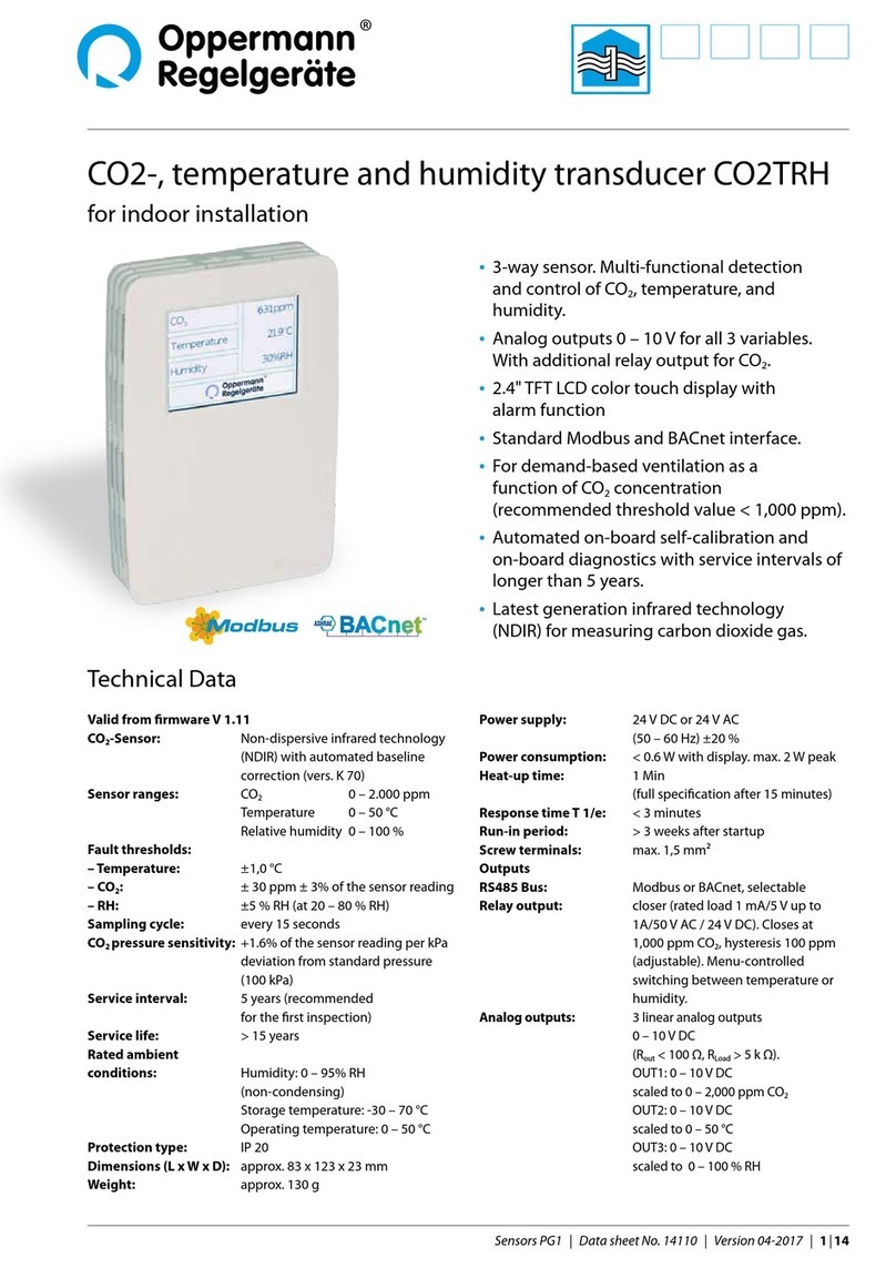
Oppermann Regelgeräte
Oppermann Regelgeräte CO2TRH manual

Soundmask
Soundmask SM-T-1200 operating manual
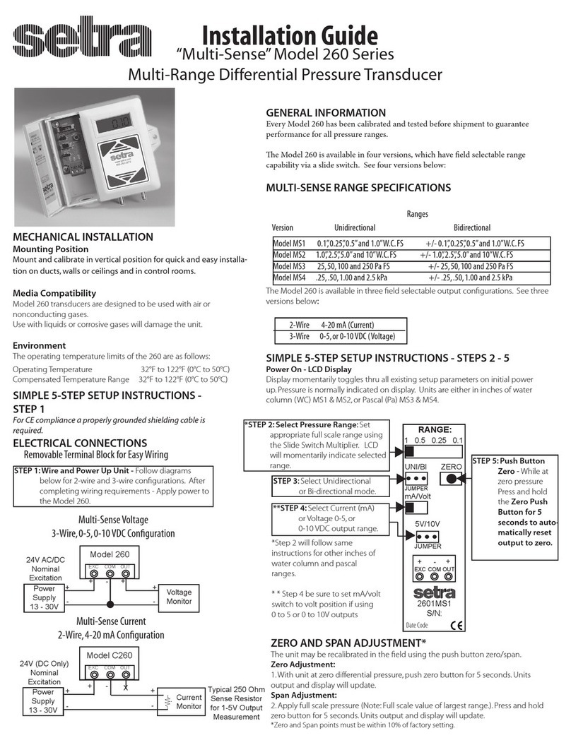
Setra Systems
Setra Systems Multi-Sense 260 Series installation guide
halstrup-walcher
halstrup-walcher PS11 instruction manual
novotechnik
novotechnik LS1 Series manual
Balluff
Balluff BTL7-A M Series user guide
