9
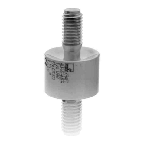
U2B
HBMA03823.3en/de/fr
2.3 Measurement process, output signal
A force acting upon the transducer will elasticallydeform the SGs applied to
the measuring body. Their electrical resistance then changes in proportion to
the change in their length. This disturbs the balancing of the measurement
system wired in the form of a Wheatstone bridge, resulting in an output vol
tage UAat contacts 1 and 4 if a bridge excitation voltage UBis present at
points 2 and 3 on the bridge.
The ratio between the voltages, UA/UB, expressed in mV/V, is a measure of
the sensitivityof the force transducer. The change in output voltage UAis
linear to the acting force. Provided the force transducer is connected in ac
cordance with Fig. 5.1 and as specified in the User Manual for the amplifier
concerned, compressive forces are displayed with a positive operating sign
and tensile forces are shown with a negative operating sign. The force trans
ducer is electricallyconnected in 6wire mode (see Section 5.2). To reverse
the polarity, the white and red wires in the cable should be transposed.
2.4 Compensating for disturbance variables
The geometryof the measuring bodyand the positioning of the SGs ensure
that the output signal from the transducer suffers onlyminimal distortion if the
force being measured is affected bysuperimposed lateral forces and/or torsio
nal and bending moments. The specifications for this can be found in the
Technical Data. In the interests of greater accuracy, however, it is generally
better to tryto prevent spurious loadings of this kind altogether. The U2B also
has separate lateral force compensation which reduces lateral force influ
ences to a minimum (see Technical Data).
The influence of temperature on the zero signal and sensitivityare compensa
ted. Changes in ambient pressure have the same effect as additive (substrac
tive) forces (see Section 3.3).


