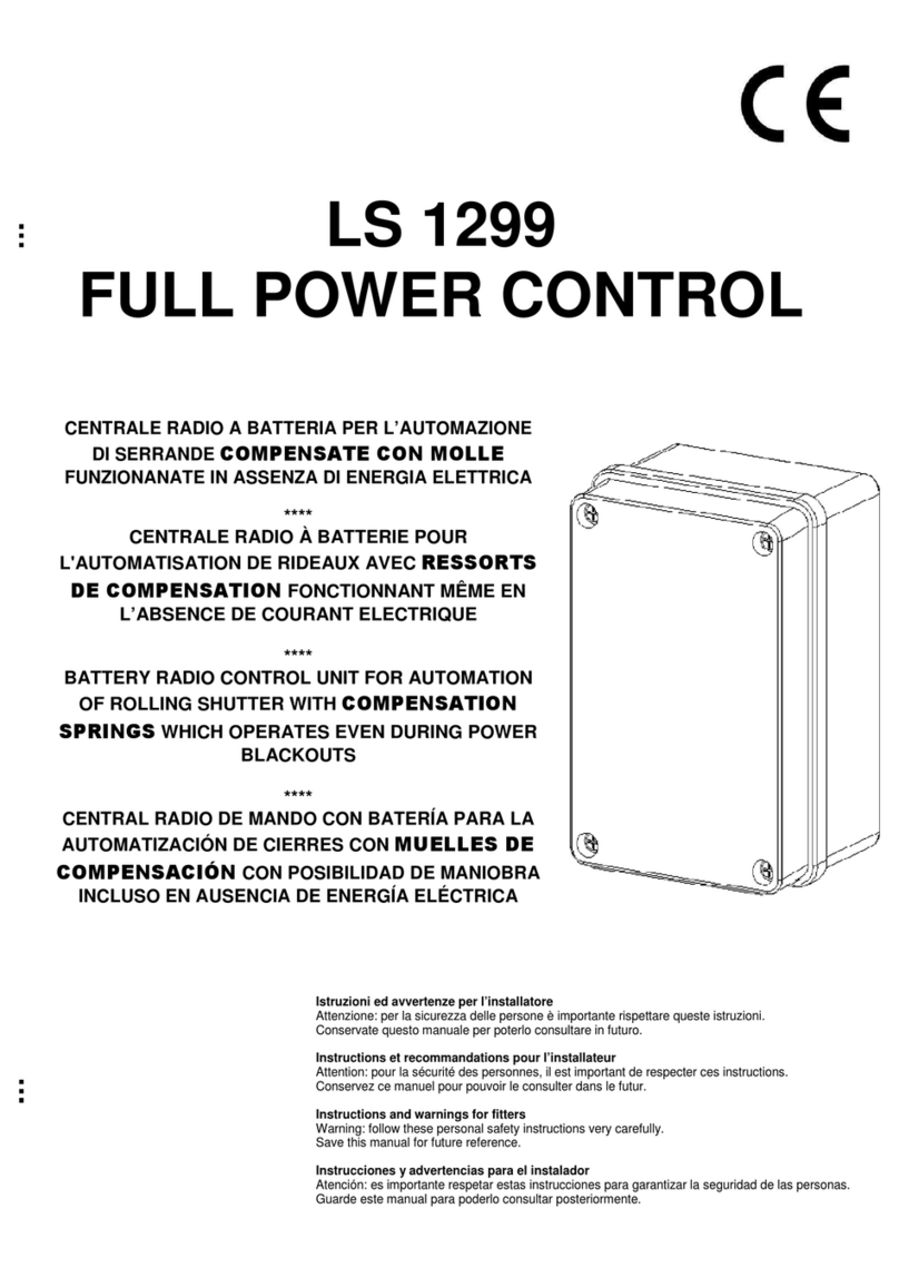
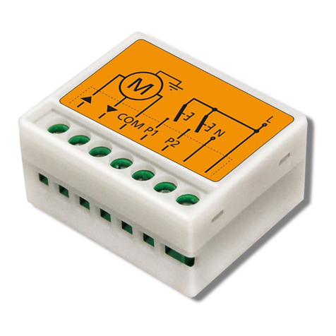
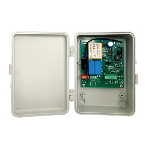
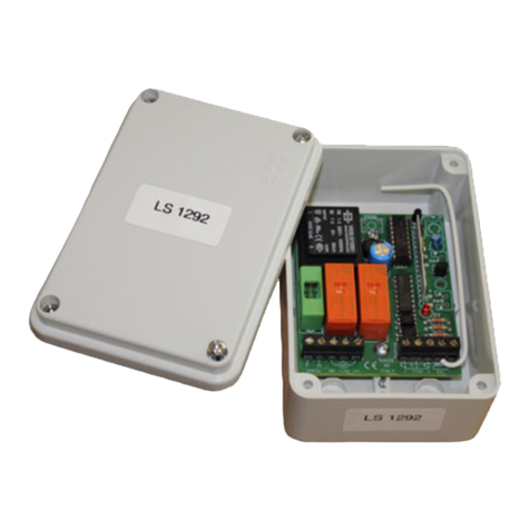
ACM SPOT Product manual

Istruzioni ed avvertenze per l’installatore
Attenzione: per la sicurezza delle persone è importante rispettare queste istruzioni.
Conservate questo manuale per poterlo consultare in futuro.
Instructions et recommandations pour l’installateur
Attention: pour la sécurité des personnes, il est important de respecter ces instructions.
Conservez ce manuel pour pouvoir le consulter dans le futur.
Instructions and warnings for fitters
Warning: follow these personal safety instructions very carefully.
Save this manual for future reference.
Instrucciones y advertencias para el instalador
Atención: es importante respetar estas instrucciones para garantizar la seguridad de las personas.
Guarde este manual para poderlo consultar posteriormente.
Anweisungen und Hinweise für den Installateur
Achtung: für die Sicherheit von Personen ist es wichtig, sich an diese Anweisungen zu halten.
Die vorliegende Anleitung für zukünftiges Nachschlagen aufbewahren.
SPOT

2
ISPOT
SPOT- Centrale da esterno per tende da sole e tapparelle
ISTRUZIONI PER L’INSTALLAZIONE, USO E MANUTENZIONE
ATTENZIONE
Prima di procedere all’installazione e alla programmazione della centralina leggere atten-
tamente le istruzioni. Seguire scrupolosamente le indicazioni riportate. Una non corretta
installazione può provocare gravi rischi. Il costruttore declina ogni responsabilità nel ca-
so di non corretta installazione o d’uso improprio del prodotto.
SOMMARIO
1. DESCRIZIONE DEL PRODOTTO
2. MEMORIZZAZIONE DEL RADIOCOMANDO MADRE E LOGICA DI FUNZIONAMENTO
3. AGGIUNTA DI NUOVI RADIOCOMANDI (TX2COLOR - TX4 - TXP - TX FLAT)
4. LOGICA DI FUNZIONAMENTO DEL PULSANTE ESTERNO DI COMANDO
5. PROGRAMMAZIONE DI UN RADIOCOMANDO “GLOBALE” (TX2COLOR - TX4 - TXP - TX FLAT)
6 CANCELLAZIONE DEI CODICI DEI RADIOCOMANDI
7.
INSTALLAZIONE DELL’ANEMOMETRO WINDY
8.
PROGRAMMAZIONE DELLA VELOCITÀ DI INTERVENTO DELL’ANEMOMETRO
9.
INVERSIONE DEL SENSO DI MARCIA
10. AVVERTENZE PER L’INSTALLAZIONE
11. CARATTERISTICHE TECNICHE
12. SCHEMA DEI COLLEGAMENTI ELETTRICI
13. SEGNALAZIONI IN PROGRAMMAZIONE
1. DESCRIZIONE DEL PRODOTTO
La centralina “SPOT” è un sistema di automazione per tende e tapparelle dotato di scheda elettronica
radioricevente supereterodina incorporata; il dispositivo è comandato da radiocomandi funzionanti
nella banda di frequenza 433,92 MHz.
2. MEMORIZZAZIONE DEL RADIOCOMANDO MADRE E LOGICA DI FUNZIONAMENTO
Il primo radiocomando che viene memorizzato è definito “MADRE” ed acquisisce automaticamente
le seguenti caratteristiche:
- Determina il verso di azionamento della tenda da sole/tapparella in base al tasto utilizzato durante
la fase di memorizzazione.
- É l’unico radiocomando che può attivare la fase di programmazione.
Se durante la fase di memorizzazione del radiocomando MADRE, fossero presenti ulteriori centraline
SPOT sulle quali ancora non è stato memorizzato il radiocomando madre, è opportuno scollegare que-
st’ultime dalla rete di alimentazione, in modo da evitare che più centraline memorizzino lo stesso ra-
diocomando MADRE.
Nel caso in cui si desideri invertire la logica di funzionamento dei tasti del radiocomando “MADRE”
seguire le istruzioni a paragrafo 9.
Per memorizzare il radiocomando “MADRE” procedere come illustrato di seguito.

3
ISPOT
1. Alimentare la centralina;
2. Premere e mantenere premuti ambedue i tasti del radiocomando (pulsante “PROG” per i TX FLAT”)
finché il motoriduttore non segnalerà tramite due movimenti brevi sulla tenda/tapparella, uno di sa-
lita e l’altro di discesa, l’entrata in programmazione.
3. Premere il tasto del radiocomando “MADRE” da memorizzare; a questo punto la centralina me-
morizza il radiocomando “MADRE” ed esce automaticamente dallo stato di programmazione.
La pressione del tasto “UP” del radiocomando permetterà l’alzata della taparella, viceversa, il ta-
sto “DOWN” permette l’abbassamento. Durante la corsa, la pressione del tasto opposto al movi-
mento causerà lo “STOP” della tenda (o tapparella): dalla posizione di riposo premendo il tasto
“UP” la tapparella si alza, una nuova pressione del suddetto tasto non causerà alcunché e la tap-
parella continuerà nella sua corsa, invece pigiando il tasto “DOWN” la tenda si arresta; viceversa
per la corsa in discesa.
3. AGGIUNTA DI NUOVI RADIOCOMANDI (TX2COLOR - TX4 - TXP - TX FLAT)
La centralina elettronica “
SPOT
” è in grado di memorizzare altri venti radiocomandi oltre al “MADRE”.
Qualora si desideri memorizzare ulteriori radiocomandi occorre procedere come illustrato in seguito:
1. Alimentare la centralina;
2. Premere e mantenere premuti ambedue i tasti del radiocomando “MADRE” finché il motoriduttore
non segnalerà, tramite due movimenti brevi della tenda/tapparella, uno di salita e l’altro di discesa,
l’entrata in programmazione1;
3. Premere un tasto del nuovo radiocomando da memorizzare; a questo punto la centralina me-
morizza il nuovo radiocomando ed esce automaticamente dallo stato di programmazione.
1L’entrata in programmazione è possibile solo attraverso il radiocomando “MADRE”.

4
ISPOT
Qualora si volessero memorizzare ulteriori radiocomandi procedere dal punto 2; qualora si tentas-
se di memorizzare più di venti radiocomandi (escluso il “MADRE”) la centralina provvederà alla
cancellazione del primo radiocomando memorizzato e così di seguito per ulteriori nuovi radioco-
mandi, vedi fig. 3.
4. LOGICA DI FUNZIONAMENTO DEL PULSANTE ESTERNO DI COMANDO
E’ possibile installare un pulsante opzionale esterno (bassa tensione 24 V d.c.) di comando da parete per la
movimentazione della tenda anche senza l’uso del radiocomando. La logica di funzionamento è di tipo pas-
so-passo: ad ogni pressione del pulsante il motoriduttore esegue in modo sequenziale i comandi di salita,
stop, discesa, stop. Il pulsante esterno di comando dovrà essere collegato ai cavi colore rosso e nero; per
l’installazione vedere schema dei collegamenti elettrici al paragrafo 12.
5. PROGRAMMAZIONE DI UN RADIOCOMANDO “GLOBALE” (TX2COLOR - TX4 - TXP - TX FLAT)
In un installazione con più tende motorizzate può nascere l’esigenza di avere un unico radiocomando,
denominato “GLOBALE”, vedi fig. 4, in grado di forzare l’apertura o la chiusura contemporanea di tutte
o di un gruppo di tende (o tapparelle).
Prima di procedere alla memorizzazione di un RADIOCOMANDO “GLOBALE” su ogni centralina è ne-
cessario che tutti i “MADRE” siano concordi nel verso di movimentazione della tenda (o tapparella), ov-
vero che abbiano tutti il tasto UP per che effettui la salita e il DOWN per la discesa.
Procedere alla memorizzazione del RADIOCOMANDO “GLOBALE” nel modo indicato nel paragra-
fo 3 per tutte le tende da movimentare.
Z
V
FIG.3
FIG.4

ISPOT
5
6. CANCELLAZIONE DEI CODICI DEI RADIOCOMANDI (compreso il “MADRE”)
Può nascere la necessità di cancellare tutti i codici dei radiocomandi memorizzati, compreso il ”MA-
DRE” (nel caso di smarrimento); a tal proposito premere e tener premuto il pulsante esterno (in posi-
zione di stop) finché la centralina non segnala, attraverso tre brevi cicli consecutivi di “SALITA” e “DI-
SCESA” della tenda (o tapparella), l’avvenuta cancellazione dei codici.
In assenza di pulsante esterno questa procedura può essere eseguita simulando l’azionamento del pul-
sante mettendo a contatto i cavi di colore rosso e nero (comando a bassa tensione vedi par. 12).
Si ricorda che nella successiva fase di memorizzazione di nuovi codici, il primo radiocomando me-
morizzato sarà codificato e riconosciuto dalla centralina come il nuovo “MADRE”.
Per la memorizzazione del nuovo radiocomando madre seguire procedura indicata nel paragrafo 2.
7.
INSTALLAZIONE DELL’ANEMOMETRO WINDY
Un eventuale eccesso di vento può danneggiare la struttura portante della tenda e la tenda stessa, per
ovviare a ciò, la centralina “SPOT” è predisposta per l’installazione di un anemometro.
L’anemometro va installato nei pressi della tenda ben esposto al vento, e collegato ai cavi di colore
rosso e bianco, per i collegamenti vedi fig. 6 paragrafo 12.
La soglia dell’intervento dell’anemometro è impostata a 15 Km/h .
N.B. L’intervento dell’anemometro causa l’inibizione del funzionamento del radiocomando e del pul-
sante esterno per circa 8 minuti.
Attenzione ! verificare che l’intervento dell’anemometro faccia compiere effettivamente la corsa di chiu-
sura della tenda, se cosi non fosse, invertire il senso di marcia ( vedi par. 9 ) oppure invertire le fasi di ali-
mentazione del motore (nero e marrone vedi fig.6)
8. PROGRAMMAZIONE DELLA VELOCITA’ DI INTERVENTO DELL’ANEMOMETRO.
La Spot permette di impostare la velocità di intervento dell’anemometro (15 Km/h o 30 Km/h) agendo
esclusivamente sul radiocomando “MADRE”.
Per effettuare la programmazione procedere come segue:
1) Alimentare la “Spot”;
2)
Premere e mantenere premuti ambedue i tasti del radiocomando “MADRE” finchè il motoriduttore non se-
gnalerà, tramite due movimenti brevi della tenda, uno di apertura e chiusura, l’entrata in programmazione
;
3) Premere un tasto qualsiasi del radiocomando “MADRE”:
Il motoriduttore segnalerà lo stato attuale di impostazione della velocità di intervento dell’anemo-
metro nel seguente modo:
• un movimento breve del motoriduttore nei due sensi (apertura/chiusura) 15Km/h
• 2 movimenti brevi del motoriduttore nei due sensi (apertura/chiusura/apertura/chiusura) 30Km/h
4) A questo punto se si desidera variare la velocità di soglia premere un tasto qualsiasi del radioco-
mando “MADRE”: ad ogni pressione del tasto il motoriduttore segnalerà (come indicato al punto 3)
lo stato di impostazione della velocità di soglia.
5) Impostata la velocità desiderata sarà sufficiente far trascorrere circa 15s, senza effettuare alcuna
operazione, per uscire dalla programmazione.
N.B.! Nel caso di smarrimento del radiocomando madre per effettuare la programmazione della velo-
cità di soglia è necessario cancellare i codici in memoria e rimemorizzare il radiocomando madre (se-
guire le indicazioni del paragrafo 6).
9. INVERSIONE DEL SENSO DI MARCIA
Può nascere l’esigenza di invertire il senso di marcia, per far si che il tasto UP faccia effettivamente la salita.
Per invertire il senso di rotazione premere e tener premuti entrambi i tasti del radiocomando “MADRE”, la cen-
trale segnala, tramite due movimenti brevi della tenda (o tapparella), uno di salita e l’altro di discesa, l’entrata
in programmazione; a questo punto premere il pulsante esterno (rosso/nero); l’avvenuta inversione è segnalata
dalla centralina tramite due brevi movimenti di “SALITA” e due di “DISCESA” della tenda (o tapparella).
10. AVVERTENZE PER L’INSTALLAZIONE
• La centralina SPOT deve essere installata unicamente da personale qualificato ed uti-
lizzata solamente per movimentare motoriduttori tubolari per tende o tapparelle.

• L’installatore deve provvedere alla protezione del dispositivo per mezzo di interruttore magnetoter-
mico differenziale (con separazione tra i contatti di almeno 3 mm) che assicuri il sezionamento on-
nipolare dalla rete elettrica in caso di guasto.
• Il cablaggio fornito unitamente al dispositivo deve essere sostituito, in caso di guasto, dal costruttore
o da personale qualificato.
11. CARATTERISTICHE TECNICHE
Alimentazione: 230 V a.c.
Portata contatti relè: 5 A
Sensibilità ricevitore: -105 dBm per S/N = 17 dB con modulazione portante 100%
Alimentazione pulsante esterno: 24 V d.c.
Tempo motore: 120 s
Il costruttore dichiara che la SPOT è conforme alla direttiva 99/05 e che sono state applicate le nor-
mative riportate in tabella:
Sicurezza elettrica Compatibilità elettromagnetica
Uso efficace dello spettro
EN 60335 I ETS 300 683 EN 300 220-3
12. SCHEMA DEI COLLEGAMENTI ELETTRICI
13. SEGNALAZIONI IN PROGRAMMAZIONE
6
ISPOT
LA SPOT SEGNALA ATTRAVERSO IL MOVIMENTO DELLA TAPPARELLA LO STATO DI PROGRAMMAZIONE
LA SPOT É IN ATTESA DI MEMORIZZA-
RE UN NUOVO RADIOCOMANDO O DI
INVERTIRE IL SENSO DI MARCIA
LA SPOT SEGNALA LʼAVVENUTA IN-
VERSIONE DEL SENSO DI MARCIA
(INSTALLAZIONE A SINISTRA)
LA SPOT SEGNALA LʼAVVENUTA CAN-
CELLAZIONE DI TUTTI CODICI DEI RA-
DIOCOMANDI

FSPOT
7
SPOT - Centrale d’extérieur pour stores et volets roulants
INSTRUCTIONS POUR L’INSTALLATION,
L’EMPLOI ET L’ENTRETIEN
ATTENTION
Avant de procéder à l’installation et à la programmation de la centrale lire attentivement les
instructions. Suivre scrupuleusement les indications reportées. Une installation incorrecte peut
provoquer de graves risques. Le constructeur décline toute responsabilité en cas d’installation
incorrecte ou de mauvaise utilisation du produit.
SOMMAIRE
1. DESCRIPTION DU PRODUIT
2. MÉMORISATION DE LA RADIOCOMMANDE “MÈRE” ET LOGIQUE DE FONCTIONNEMENT
3. AJOUT DE NOUVELLES RADIOCOMMANDES (TX2COLOR - TX4 - TXP - TX FLAT)
4. LOGIQUE DE FONCTIONNEMENT DU BOUTON EXTERIEUR DE COMMANDE
5. PROGRAMMATION D’UNE RADIOCOMMANDE « GLOBAL » (TX2COLOR - TX4 - TXP - TX FLAT)
6. ANNULLATION DES CODES RADIOCOMMANDES
7. INSTALLATION DE L’ANEMOMETRE WINDY
8. PROGRAMMATION DE LA VITESSE D’ENCLENCHEMENT DE L’ANEMOMETRE
9.
INVERSION DU SENS DE ROULEMENT
10. AVERTISSEMENTS POUR L’INSTALLATION
11. CARACTERISTIQUES TECHNIQUES
12. SCHEMA DES MONTAGES ELECTRIQUES
13. SIGNALISATIONS EN PROGRAMMATION
1. DESCRIPTION DU PRODUIT
La centrale « SPOT » est un système d’automatisation pour stores et volets roulants équipé de fiche
électronique réceptrice superhèterodine incorporée; le dispositif est commandé par des radiocom-
mandes qui fonctionnent sur la bande de fréquence 433,92 MHz.
2. MÉMORISATION DE LA RADIOCOMMANDE “MÈRE” ET LOGIQUE DE FONCTIONNEMENT
La première radiocommande qui est mémorisée est définie “MÈRE” et acquiert automatiquement les ca-
ractéristiques suivantes :
- elle détermine le sens d’ actionnement du volet roulant en fonction de la touche utilisée pendant la pha-
se de mémorisation.
- Elle est la seule télécomande qui peut activer la phase de programmation.
Si, pendant la phase de mémorisation de la radiocommande mère, sont présentes des ultérieures centrales
sur lesquelle: aucunee radiocommande n’a été mémorisée, il est conseillé de déconnecter ces dernièr du
courant de façon à éviter que plusieurs centrales mémorisent la même radiocommande mère.
Au cas où l’on désire inverser la logique du fonctionnement des touches de la radiocommande “MÈRE” ,
suivre les instructions a paragrafe 9.

8
Pour mémoriser la radiocommande “MÈRE”, procéder comme illustré ci-dessous.
1. alimenter la centrale ;
2. passer et maintenir appuyées les deux touches de la radiocomande (“PROG” bouton pour TXFLAT) jus-
qu ‘à ce que le moteur signale, par deux mouvements brefs du volet, un en montée l’ autre en descente,
l’entrée en programmation.
3. pousser la touche de la radiocommande “MÈRE” qu’il faut mémoriser ;maintenant la centrale a mémo-
risé la radiocommande “MÈRE” et sort automatiquement de la programmation.
La pression du bouton « UP » de la radiocommande permettra l’ouverture du volet roulant, vice-versa,
le bouton « Down » en permettra la fermeture. Durant la course, la pression du bouton opposé au
mouvement causera le « STOP » (arrêt) du store (ou volet roulant) : de la position de repos, en pres-
sant le bouton « UP », le volet s’ouvrira, une nouvelle pression sur le susmentionné bouton n’aura pas
d’effets et le volet roulant continuera sa course, alors qu’en poussant le bouton « DOWN » le store s’ar-
rêtera; vice-versa pour la course descendante.
3. AJOUT DE NOUVELLES RADIOCOMMANDES (TX2COLOR - TX4 - TXP - TX FLAT)
La centrale électronique « SPOT » est capable de mémoriser vingt autres radiocommandes en plus
de « MÈRE ». Lorsque l’on désire mémoriser ulterieur radiocommandes procéder comme illustré ci
dessous:
1. Alimenter la centrale;
2. Presser et maintenir pressés les deux boutons de la radiocommande « MÈRE » jusqu’à ce que le mo-
to-réducteur signale l’entrée en programmation1, par deux mouvements brefs du store volets roulants,
un d’ouverture et un de fermeture;
3. Presser un bouton de la nouvelle radiocommande que l’on veut mémoriser; la centrale mémorise
alors la nouvelle radiocommande et sort automatiquement de l’état de programmation.
1L’entrée en programmation est possible uniquement à travers la radiocommande « MÈRE ».
FSPOT

FSPOT
9
Au cas où l’on voudrait mémoriser d’autres radiocommandes, procéder à partir du point 2; au cas où
l’on tenterait de mémoriser plus de sept radiocommandes (« MÈRE » excluse) la centrale s’occupera
d’annuler la première radiocommande mémorisée et ainsi de suite pour les nouvelles radiocom-
mandes supplémentaires, voir fig.3.
4. LOGIQUE DE FONCTIONNEMENT DU BOUTON EXTERIEUR DE COMMANDE
Il est possible d’installer un bouton de commande optionnel extérieur (basse tension 24 V d.c.) de pa-
roi pour le déplacement du store même sans l’utilisation de la radiocommande. La logique de fonc-
tionnement est du type pas à pas: à chaque pression du bouton, le moto-réducteur exécute de façon
séquentielle les commandes d’ouverture, arrêt, fermeture, arrêt. Le bouton extérieur de commande de-
vra être connecté aux câbles de couleurs rouge et noire; pour l’installation voir le schéma des mon-
tages électriques, paragraphe 12.
5. PROGRAMMATION D’UNE RADIOCOMMANDE « GLOBAL » (TX2COLOR - TX4 - TXP - TX FLAT)
Dans une installation comprenant plusieurs stores motorisés, on pourrait ressentir le besoin d’avoir un
seul transmetteur portable, dénommé « GLOBALE », voir fig.4, capable de forcer en même temps l’ou-
verture ou la fermeture de tous ou d’un groupe de stores (ou volets roulants).
Avant de procéder à la mémorisation d’un RADIOCOMMANDE « GLOBAL » sur chaque centrale il est
nécessaire que toutes les RADIOCOMMANDE « MÈRE » soient synchrones dans le sens de déplacement
du store (ou volet roulant), c’est-à-dire qu’à tous les boutons UP corresponde l’ouverture et qu’à tous les
boutons DOWN la fermeture.
FIG.3
FIG.4
RADIOCOMMANDE
“GLOBAL”

10
FSPOT
Procéder à la mémorisation de la radiocommande « GLOBAL » selon les indications du paragraphe 3
pour tous les stores à activer.
6. ANNULATION DES CODES DES RADIOCOMMANDES (« MÈRE » incluse)
On pourrait avoir besoin d’annuler tous les codes des radiocommandes mémorisées, inclus celui de «
MÈRE » (en cas de perte); dans ce cas, presser et tenir pressé le bouton extérieur (en position d’arrêt)
jusqu’à ce que la centrale signale l’effective annulation des codes, par trois cycles consécutifs brefs de
« OUVERTURE » et « FERMETURE » du store (ou volet roulant). En l’absence de bouton poussoir
externet cette procedure peut être éxécutée en simulant l’actionnement du boutton poussoir en met-
tant en contact les câbles de couleur rouge et noir (commande à basse tension v.c.f. part. 12).
Nous vous rappelons que dans la phase successive de mémorisation de nouveaux codes, la première ra-
diocommande mémorisée sera codifiée et reconnue par la centrale comme la nouvelle « MÈRE ».
Pour mémoriser la nouvelle radiocommande mère, suivre la procédure indiquée au paragraphe 2.
7. INSTALLATION DE L’ANEMOMETRE WINDY
Un éventuel excès de vent peut endommager la structure portante du store et le store lui-même, pour remé-
dier à ce problème, la centrale « SPOT » est prédisposée à l’installation d’un anémomètre.
L’anémomètre doit être installé près du store bien exposé au vent, et connecté aux câbles de couleurs Rouge
et blanche, pour les montages électriques voir fig. 6 paragraphe 12.
Le seuil d’intervention de l’anémomètre peut être positionné sur deux vitesses : 15 km/h ;
N.B. L’INTERVENTION DE L’ANEMOMETRE CAUSE L’INHIBITION DU FONCTIONNEMENT DE LA
RADIOCOMMANDE ET DU BOUTON EXTERIEUR PENDANT 8 MINUTES ENVIRON.
Attention ! Vérifier que l’intervention de l’anémomètre fasse effectivement effectuer la course de fer-
meture du store. Si ce n’est pas le cas, invertir le sens de marche (cf. par. 9) dubien invertir les phases
d’alimentation du moteu (noir et marron voir fig.6)
8. PROGRAMMATION DE LA VITESSE D’ENCLENCHEMENT DE L’ANEMOMETRE.
L’appareil Spot permet de programmer la vitesse d’enclenchement de l’anémomètre (15 Km/h ou 30
Km/h) en agissant uniquement sur la radiocommande "MERE".
La programmation s’effectue de la façon suivante:
1) Alimenter le "Spot";
2) Appuyer, et rester appuyé sur les deux touches de la radiocommande " MERE " jusqu’à ce que le
motoréducteur signale, par deux mouvements brefs du store, (l’un montant, l’autre descendant), le
démarrage du mode programmation;
3) Appuyer sur n’importe quelle touche de la radiocommande "MERE ":
Le motoréducteur va alors indiquer les paramètres actuels de vitesse d’enclenchement de l’anémo-
mètre, de la façon suivante:
•1
mouvement bref du motoréducteur dans les deux sens (ouverture/fermeture); 15Km/h
•2
mouvements brefs du motoréducteur dans les deux sens (ouverture/fermeture/ouverture/fermeture); 30Km/h
4) A ce moment-là, il est possible de modifier la vitesse de seuil en appuyant sur n’importe quelle tou-
che de la radiocommande " MERE " : à chaque pression de la touche, le motoréducteur indiquera
(tel que décrit au point 3) les paramètres actuels de la vitesse de seuil.
5) Une fois la vitesse programmée, il suffit de laisser passer 30 secondes sans effectuer aucune opéra-
tion pour quitter le mode programmation.
N.B! Important! En cas de defaillance de la radiocommande “ mere”, la programmation de la vitesse
de seuil s’effectue les codes memorises et en reprogrammant le memoire de la radiocommande “ me-
re “ (suivre les instruction du paragraphe 6)
9.
INVERSION DU SENS DE ROULEMENT
On pourrait avoir besoin d’inverser le sens de roulement de façon à ce que le bouton UP provoque
effectivement l’ouverture.
Pour inverser le sens de rotation presser et tenir pressés les deux boutons
du radioguidage « MÈRE », la centrale signale l’entrée en programmation par deux mouvements
brefs du store (ou volet roulant), un d’ouverture et l’autre de fermeture; presser alors le bouton ex-
térieur (rouge/noir); l’effective inversion est signalée par la centrale par deux mouvements brefs de
« OUVERTURE » et deux de « FERMETURE » du store (ou volet roulant).

FSPOT
11
10. AVERTISSEMENTS POUR L’INSTALLATION
• La centrale SPOT doit être installée uniquement par du personnel qualifié et utilisée seu-
lement pour activer des moto-réducteurs tubulaires pour stores ou volets roulants.
• L’installateur doit faire le nécessaire pour la protection du dispositif à travers un interrupteur ma-
gnétothermique différentiel (avec séparation entre les contacts d’au moins 3 mm) qui assure le sec-
tionnement omnipolaire du réseau électrique en cas de panne.
• Le câblage fourni avec le dispositif doit être remplacé, en cas de panne, par le constructeur ou par
du personnel qualifié.
11. CARACTERISTIQUES TECHNIQUES
Alimentation : 230 V a.c.
Portée contacts relais: 5 A
Sensibilité récepteur: - 105 dBm pour S/N = 17 dB avec modulation porteuse 100%
Alimentation bouton extérieur: 24 V d.c.
Temps du moteur: 120 s
Le constructeur déclare que SPOT est conforme à la directive 99/05 et que les normes reportées dans
le tableau ont été appliquées:
Securite electrique Compatibilite Electromagnetique Emploi efficacedu spectre
EN 60335 I ETS 300 683 EN 300 220-3
12.
SCHEMA DES MONTAGES ELECTRIQUES
13. SIGNALISATIONS EN PROGRAMMATION
LE SPOT SIGNALE À TRAVERS LE MOUVEMENTDU VOLET L'ÉTAT DE LA PROGRAMMATION
LE SPOT EST EN ATTENTE DE
MÉMORISER UNE NOUVELLE RADIOCOM-
MANDE OU D'INVERSER LE SENS DE LA
MARCHE
LE SPOT SIGNALE L'INVERSION DU SENS
DE LA MARCHE (INSTALLATION À GAU-
CHE)
LE SPOT SIGNALE L'ANNULATION DE
TOUS LES CODES DES RADIOCOMMAN-
DES

12
GB SPOT
SPOT - External central control unit for rolling shutter and awming
INSTRUCTIONS FOR INSTALLATION, USE AND MAINTENANCE
ATTENTION
Read the instructions carefully before starting to install and programme the control unit.
Follow the instructions scrupulously. Incorrect installation may create serious risks. The
manufacturer declines all liability in the event of incorrect installation or improper use of
the product.
SUMMARY
1. DESCRIPTION OF THE PRODUCT
2. MOTHER RADIO CONTROL SWITCH MEMORISATION AND OPERATING LOGIC
3. ADDITION OF NEW RADIO CONTROL UNITS (TX2COLOR - TX4 - TXP - TX FLAT)
4. LOGIC OF FUNCTIONING OF THE CONTROL EXTERNAL PUSH BUTTON
5. PROGRAMMING OF A GLOBAL RADIO CONTROL SWITCH (TX2COLOR - TX4 - TXP - TX FLAT)
6. CANCELLATION OF RADIO CONTROL CODES
7.
INSTALLATION OF THE ANEMOMETER WINDY
8. PROGRAMMING THE ANEMOMETER WINDY
9. INVERSION OF THE DIRECTION OF MOVEMENT
10. WARNINGS FOR INSTALLATION
11. TECHNICAL CHARACTERISTICS
12.
ELECTRICAL CONNECTION DIAGRAM
13. INDICATORS UNDER DEVELOPMENT
1. DESCRIPTION OF THE PRODUCT
The “SPOT” control unit is a system for automation of rolling shutter and awming with a radio receiver
super-heterodyne electronic card incorporated. The device is controlled by radio control code work-
ing in the 433,92 MHz frequency band.
2. MOTHER RADIO CONTROL SWITCH MEMORISATION AND OPERATING LOGIC
The first radio control switch to be memorised is known as the “MOTHER” and automatically acqui-
res the following characteristics:
- It establishes the roller window blind/awning direction of movement on the basis of the key used du-
ring the memorisation phase.
- It is the only radio control switch able to activate the programming phase.
If, memorising the mother radio control, are present other Spot central control on which no mother ra-
dio control is memorised, you should disconnect these central control from electrical alimentation to
avoid that several control units memorize the same mother radio control.
Follow the instructions provided on paragraph 9 if you wish to invert the operating logic of the “MO-
THER” radio control keys.
Proceed as follows to memorise the “MOTHER” radio control switch.

GB SPOT
13
1. Connect the control unit to the power supply;
2. Press and hold down both buttons of the radio control (“PROG” button for TXFLAT) until two brief
movements of the blind/awning (one up and one down) are observed. This indicates that Spot is in
programming mode.
3. Press a key on the “MOTHER” radio control switch to be memorised. At this point the Spot
memorises the “MOTHER” radio control switch and automatically exits from programming
mode.
Pressing the “UP” button of the radio control unit raises the blind, whereas pressing the “DOWN” but-
ton lowers it. When the blind is moving, pressing the “STOP” button will halt movement of the blind.
When the UP button is pressed in the resting position, the blind is raised. Pressing the same button
again will have no effect and the blind will continue its run. On the other hand, if the DOWN button
is pressed the blind stops. Vice versa for the down run.
3. ADDITION OF NEW RADIO CONTROL UNITS (TX2COLOR - TX4 - TXP - TX FLAT)
The “SPOT” electronic control unit can memorise other twenty radio commands in addition to the
“MOTHER”. In case you wish to add new codes in the receiver, the following procedure must be
followed.
1. Connect the control unit to the power supply;
2. Press and hold down both buttons of the “MOTHER” radio control unit until the motor control unit
signals the start of programming1through two brief movements of the blind roller shutters, one up-
wards and the other downwards.
3. Press a key on the new radio control unit to be memorised. At this point the central control unit
memorises the new radio control unit and exits automatically from programming status.
1Programming status can be entered only through the “MOTHER” radio control

14
If one wants to memorise additional radio control units, resume from point 2 above. If an attempt is
made to memorise more than seven radio control units (in addition to the “MOTHER”) the control unit
will cancel the first one memorised, and so on in sequence for further radio control units (see fig. 3).
4. LOGIC OF FUNCTIONING OF THE EXTERNAL CONTROL PUSH BUTTON
It is possible to install an optional external wall-mounted push button (low voltage 24 V d.c.) to move
the blind even without using the radio control unit. The logic of functioning is step by step. Every time
the push-button is pressed, the motor reducer executes the Up, Stop, Down, Stop actions sequential-
ly. The external push button must be connected to the red and black coloured wires. For its installa-
tion see the electrical connection diagram in paragraph 12.
5. PROGRAMMING OF A GLOBAL RADIO CONTROL SWITCH (TX2COLOR - TX4 - TXP - TX FLAT)
In an installation with a number of motorised blinds, there may be a need to have a single transmitter
mobile, denominated “GLOBAL”, see fig. 4, that can force opening or closure of all the group of blinds
simultaneously.
Before proceeding to memorise a “GLOBAL” RADIO CONTROL CODE on each control unit, all the
“MOTHER” RADIO CONTROL CODE must be coordinated for direction of movement of the blinds,
that is, they must all have the UP key for movement up and DOWN for movement down.
Proceed to memorise the “GLOBAL” RADIO CONTROL CODE in the way indicated in paragraph 3
for all the blinds to be moved.
RADIO
CONTROL CODE
MOTHER
RADIO CONTROL CODE
A
RADIO CONTROL CODE
B
RADIO CONTROL CODE
G
NEW
RADIO CONTROL CODE
H
FIG.3
FIG.4
“GLOBAL”
RADIO CONTROL CODE
GB SPOT
VZ

GB SPOT
15
6. CANCELLATION OF RADIO CONTROL CODES
It may become necessary to cancel all the radio command codes memorised, including the “MOTH-
ER” (in case of loss). To do so, press and hold down the external push button (in stop position) until
the central unit signals that the codes have been cancelled through three short consecutive UP and
DOWN cycles of the blind.
When the external push button is missing, the following procedure can be carried out by simulating
the putting on of the push button, through the connection of the red and black cable (low tension com-
mands, see paragraph 12).
Remember that in the subsequent memorising of new codes, the first radio command will be coded
and recognised by the central unit as the new “MOTHER”.
For the memorizing procedure of the “Mother” Remote Control, please follow the method indicated
in paragraph 9, or to invert the motor power supply cables (black and brown F.6)
7. INSTALLATION OF THE ANEMOMETER WINDY
If the wind is too strong it may damage the bearing structure of the blind or the blind itself. To
prevent that, the “SPOT” control unit has been prepared for installation of an anemometer.
The anemometer is installed near the blind, well exposed to the wind, and connected to the red and
white wires. For the electrical connections see fig. 6 paragraph 12.
The anemometer intervention threshold can be set for 2 speeds; 15 kph.
N.B. INTERVENTION BY THE ANEMOMETER INHIBITS OPERATION OF THE RADIO CONTROL
UNIT AND OF THE EXTERNAL PUSH BUTTON FOR ABOUT 8 MINUTES.
Warning! Verify that the intervention of the anemometer actually completes the closure run of the
awnings, if this were not the case, invert the direction (see paragraph 2).
8. PROGRAMMING THE ANEMOMETER’S TRIPPING SPEED
Using the Spot, you can set the tripping speed of the anemometer (15 km/h or 30 km/h) simply by us-
ing the "MOTHER" radio control.
Programming should be performed as follows:
1) Power the “Spot”;
2) Press and hold down both the keys on the “MOTHER” radio control until the gear motor (through
two brief awming movements, one upwards and the other downwards), displays entry into pro-
gramming mode;
3) Press any key on the “MOTHER” radio control; The gear motor will display the anemometer’s cur-
rent tripping speed setting as follows:
• a brief gear motor movements in each direction (opening/closing) 15 km/h
• 2 brief gear motor movements in each direction (opening/closing/opening/closing) 30 km/h
4)
At this point, if you wish to alter the tripping speed, press any button on the "MOTHER" radio control:
Each time the key is pressed, the gear motor will show the tripping speed setting (as described in point 3).
5) Once the desired speed is set, in order to exit programming mode, simply wait approximately 30
seconds without performing any operations.
N.B.! if the “mother” radio control is lost, in order to programme the tripping speed you will need to can-
cel the stored codes and re-programme the “mother” radio control (follow the instructions in paragraph 7).
9. INVERSION OF THE DIRECTION OF MOVEMENT
A need to reverse the direction of movement may arise, to ensure that the UP key actually makes the
blind move up. To invert the direction of rotation, press and hold down both keys of the “MOTHER”
radio control. The central unit signals entry into programming status by two brief movements of the
blind (one up and one down). At that point press the external push button (red/black). Inversion is sig-
nalled by the central unit by means of two brief movements of the blind, UP and DOWN.
10. WARNINGS FOR INSTALLATION
• The SPOT central control unit must be installed only by qualified personnel and used
only to operate tubular motor-reducers for sun or window roller blinds.

16
GB SPOT
• The installer must provide for protection of the device by means of a differential magnetothermic
breaker (with at least 3 mm distance between the contacts) that ensures separation of all poles from
the mains in the event of a fault.
• In the event of a fault, the wiring supplied with the device must be replaced by the manufacturer or
by qualified personnel.
11. TECHNICAL CHARACTERISTICS
Power supply: 230 V AC
Relay contact rating: 5 A
Receiver sensitivity – 105 dBm for S/N = 17 dB with carrier modulation 100%.
Power supply to external push button: 24 V DC
Motor working time: 120 s
The manufacuturer declares the SPOT conforms to Directive 99/05 and that the standards shown in
the table have been applied.
Electrical safety Electromagnetic compatibility
Efficacious use of the spectrum
EN 60335 I ETS 300 683 EN 300 220-3
12. ELECTRICAL CONNECTION DIAGRAM
13. INDICATORS UNDER DEVELOPMENT
SPOT INDICATES THE PROGRAMMING STATUS THROUGH THE MOVEMENT OF THE BLIND
SPOT IS WAITING TO RECORD A NEW RA-
DIO COMMAND OR TO REVERSE THE DI-
RECTION
SPOT INDICATES THAT THE DIRECTION
HAS BEEN REVERSED (INSTALLED TO
THE LEFT)
SPOT INDICATES THAT ALL RADIO
COMMAND CODES HAVE BEEN
CANCELLED

ESPOT
17
SPOT - Central externa para toldos y persianas
INSTRUCCIONES PARA LA INSTALACIÓN,
USO Y MANTENIMIENTO
ATENCIÓN
Antes de proceder a la instalación y a la programación de la central, leer atentamente las
instrucciones. Es imprescindible seguir rigurosamente las indicaciones expresadas. Una instala-
ción incorrecta puede provocar graves riesgos. El constructor declina toda responsabilidad en ca-
so de instalación incorrecta o de uso impropio del producto.
INDICE
1. DESCRIPCIÓN DEL PRODUCTO
2. MEMORIZACIÓN DEL MANDO A DISTANCIA MADRE Y LÓGICA DE FUNCIONAMIENTO
3. ADICIÓN DE NUEVOS MANDOS A DISTANCIA (TX2COLOR - TX4 - TXP - TX FLAT)
4. LÓGICA DE FUNCIONAMIENTO DEL PULSADOR EXTERNO DE MANDO
5. PROGRAMACIÓN DE UN MANDO “GLOBAL” (TX2COLOR - TX4 - TXP - TX FLAT)
6. CANCELACIÓN DE LOS CÓDIGOS DE MANDO A DISTANCIA
7. INSTALACIÓN DEL ANEMÓMETRO “WINDY”
8. PROGRAMMACIÓN DE LA VELOCIDAD DE INTERVENCIÓN DEL ANEMÓMETRO
9. INVERSIÓN DEL SENTIDO DE MARCHA
10. ADVERTENCIAS DE INSTALACIÓN
11. CARACTERÍSTICAS TÉCNICAS
12. ESQUEMA DE LAS CONEXIONES ELÉCTRICAS
13. SEÑALIZACIONES EN PROGRAMACIÓN
1. DESCRIPCIÓN DEL PRODUCTO
La central “SPOT” es un sistema de motorización para toldos y persianas dotado de una placa elec-
trónica radio-receptora superheterodina incorporada; el dispositivo es accionado mando a distancia
que trabajan en la banda de frecuencia 433,92 MHZ.
2. MEMORIZACIÓN DEL MANDO A DISTANCIA MADRE Y LÓGICA DE FUNCIONAMIENTO
El primer mando a distancia que se memoriza se denomina “MADRE” y adquiere automáticamente las
siguientes características:
- Determina el sentido de accionamiento del toldo/persiana según la tecla utilizada durante la me-
morización.
- Es el único mando a distancia que puede activar la fase de programación.
Si durante la fase de memorización del mando a distancia Ilamado “madre”, hubieran presentes mas
centrales SPOT en las cuales no hay todavía memorizado el mando a distancia”madre”, es oportuno
desconectar estos últimos de la red de alimentación , en modo de evitar que mas de centrales memo-
ricen el mismo mando a distancia“madre”.
Si se desea invertir la lógica de funcionamiento de las teclas del mando a distancia “MADRE”, seguir
las instrucciones a apartado 9.
Para memorizar el mando a distancia “MADRE”, proceder como se indica a continuación.

18
1. Cargar la central;
2. Pulsar las dos teclas del mando (PROG bóton para TXFLAT) y no soltarlas hasta que el motorreduc-
tor indique, con dos breves movimientos de subida y bajada del toldo/persiana, que ha entrado en
fase de programación.
3. Pulsar la tecla del mando a distancia “MADRE” que se desea memorizar; hecho esto, la central me-
moriza el mando a distancia “MADRE” y sale automáticamente del estado de programación.
Pulsando el botón “UP” del mando a distancia se activa el mecanismo de subida de la persiana y vi-
ceversa pulsando el botón “DOWN” se activa el mecanismo de bajada. Si durante el recorrido de la
persiana se presiona el pulsador contrario al movimiento en ejecución, se obtendrá el “PARO-STOP”
del toldo (o persiana): partiendo de la posición de reposo con el pulsador “UP” la persiana se levanta,
presionando nuevamente este mismo pulsador nada ocurrirá y la persiana seguirá su recorrido, al con-
trario presionando el pulsador “DOWN” se obtendrá el paro de la persiana; viceversa para el recorri-
do en bajada.
3. ADICIÓN DE NUEVOS MANDOS A DISTANCIA (TX2COLOR - TX4 - TXP - TX FLAT)
La central electrónica SPOT puede memorizar otros veinté mandos a distancia además del man-
do “MADRE”. En el caso de que se desee memorizar otros mando, proceder como indicado a
continuación:
1. Cargar la central;
2. Presionar y tener presionados ambos pulsadores del mando a distancia “MADRE” hasta que el mo-
torreductor indique, a través de dos pequeños movimientos del toldo persiana, uno de subida y el
otro de bajada, la entrada en programación1;
3.
Presionar un pulsador del nuevo mando a distancia que desea memorizar; la central memoriza el nuevo
mando a distancia y sale automáticamente del estado de programación.
1La entrada en programación es posible únicamente a través del mando a distancia “MADRE”.
ESPOT

ESPOT
19
En el caso de querer memorizar más de un mando a distancia, proceder a partir del punto 2; si se tratan de
memorizar más de siete mandos (excepto el mando “MADRE”) la central eliminará el primer mando a dis-
tancia memorizado y así en adelante para los nuevos mandos a distancia, véase fig. 3.
4. LÓGICA DE FUNCIONAMIENTO DEL PULSADOR EXTERNO DE MANDO
Es posible instalar un pulsador externo (baja tensión 24 V d.c.) de mando opcional de pared para el ma-
nejo del toldo sin utilizar el mando a distancia. La lógica de funcionamiento es del tipo paso a paso: ca-
da vez que se presiona el pulsador el motorreductor realiza de manera secuencial el mando de subida,
stop, bajada, stop. El pulsador externo de mando se deberá conectar a los cables de color rojo y negro;
para la instalación ver el esquema de las conexiones eléctricas del párrafo 12.
5. PROGRAMACIÓN DE UN MANDO “GLOBAL” (TX2COLOR - TX4 - TXP - TX FLAT)
En una instalación con varios toldos motorizados puede hacerse necesario tener un único transmisor
portable, llamado “GLOBAL”, ver fig. 4, capaz de forzar la apertura o el cierre contemporáneo de to-
dos o de un grupo de toldos (o de persianas).
Antes de proceder a la memorización de un MANDO “GLOBAL” en cada Radiomatic es necesario
que todos los MANDO “MADRE” estén de acuerdo sobre la dirección de movimiento del toldo (o per-
siana), es decir asegurarse de que el pulsador UP efectúa la subida y el pulsador DOWN efectúa la
bajada.
Proceder a la memorización del MANDO “GLOBAL” según las indicaciones del párrafo 3 para todos
los toldos que se desea desplazar.
FIG.3
FIG.4
MANDO
“GLOBALE”

20
ESPOT
6. CANCELACIÓN DE LOS CÓDIGOS DE MANDO A DISTANCIA (incluso el mando “MADRE”)
Se puede hacer necesario cancelar todos los códigos de los mandos a distancia memorizados (incluso el
mando “MADRE”) (en caso de extravio). Para tal efecto, presionar y tener presionado el pulsador externo
(en posición de stop) hasta que la central indique, a través de tres pequeños ciclos consecutivos de “SUBI-
DA” y “BAJADA”, la cancelación de los códigos. Si falta el botón externo, este procedimiento puede lle-
varse a efecto simulando el accionamiento del botón para ello hay que hacer contacto entre los cables de
color rojo y negro (mando de baja tensión, ver apartado 12). Se recuerda que en la posterior fase de me-
morización de nuevos códigos, el primer mando a distancia memorizado será codificado y reconocido por
la central como el nuevo código “MADRE”. Para memorizar el nuevo radiocontrol madre,, seguir el pro-
cedimento indicado en el apartado 2.
7. INSTALACIÓN DEL ANEMÓMETRO WINDY
Un eventual exceso de viento puede dañar la estructura portante del toldo y el mismo toldo. Para obviar es-
tos inconvenientes, la central “Spot” está predispuesta para la instalación de un anemómetro. El anemóme-
tro se deberá instalar cerca del toldo, en un lugar bien expuesto al viento, y deberá conectarse a los cables
de color Rojo y Blanco; para las conexiones eléctricas véase fig. 6 párrafo 12.
El nivel umbral del anemómetro puede regularse según dos velocidades: 15 km/h
N.B. La acciòn del anemòmetro causa la inhibiciòn del funcionamiento del mando a distanzia y del pul-
sador externo por aproximadamente 8 minutos
Atención !: Asegurarse de que la intervención del anemómetro permita completar efectivamente el recorri-
do de cierre del toldo, caso contrario, invertir el sentido de la marcha (ver apdo. 3)
8. PROGRAMACIÓN DE LA VELOCIDAD DE INTERVENCIÓN DEL ANEMÓMETRO.
Spot permite programar la velocidad de intervención del anemómetro ( 15 Km/h o 30 Km/h) simplemente
mediante el uso del radiocontrol “MADRE”.
Para efectuar la programación, proceder como se indica a continuación:
1) Dar alimentación a "Spot";
2) Pulsar las dos teclas del radiocontrol “MADRE” sin soltarlas hasta que el motorreductor señale, con dos
breves movimientos de toldo (uno de subida y otro de bajada), que ha entrado en fase de programación;
3) Pulsar cualquiera de las teclas del radiocontrol “MADRE”:
El motorreductor señalará el estado actual de programación de la velocidad de intervención del anemómetro
de la siguiente manera:
• un movimiento breve del motorreductor en ambos sentidos (abertura/cierre) 15Km/h
• 2 movimientos breves del motorreductor en ambos sentidos (abertura/cierre/abertura/cierre) 30Km/h
4) Hecho esto, si se desea cambiar la velocidad de umbral, pulsar una tecla cualquiera del radiocontrol
“MADRE”: cada vez que se pulsa la tecla, el motorreductor señalará (como se indica en el punto 3) el es-
tado de programación de la velocidad de umbral.
5) Una vez establecida la velocidad deseada, basta con dejar pasar unos 30 s sin efectuar operación algu-
na para salir de la fase de programación.
NOTA: en caso de extravío del radiocontrol “madre”, para efectuar la programación de la velocidad de
umbral es necesario cancelar los códigos memorizados y rememorizar el radiocontrol “madre” (seguir las
indicaciones del apdo. 6).
9. INVERSIÓN DEL SENTIDO DE MARCHA
Puede hacerse necesario invertir el sentido de marcha de manera que el pulsador UP accione efecti-
vamente el movimiento de subida.
Para invertir el sentido de rotación presionar y tener presionados ambos pulsadores del mando a dis-
tancia “MADRE”, la central indica, a través de dos pequeños movimientos del toldo (o persiana), uno
de subida y el otro de bajada, la entrada en programación; luego presionar el pulsador externo (ro-
jo/negro). La central indica con dos movimientos de “SUBIDA” del toldo (o de la persiana) y dos de
“BAJADA” que se ha llevado a cabo la inversión.
Table of contents
Languages:
Other ACM Control Unit manuals
Popular Control Unit manuals by other brands

DMP Electronics
DMP Electronics 865 installation guide

Viessmann
Viessmann VITOTRONIC 100 Installation and service instructions

TransCore
TransCore AR2200 user guide

Anthem
Anthem MDX Crestron manual

Kaval
Kaval LINKnet OFR800 Series Installation, operation and maintenance guide

Deep Sea Electronics Plc
Deep Sea Electronics Plc DSE7450 Operator's manual