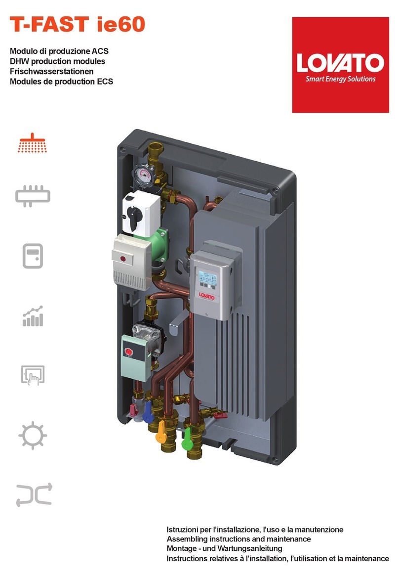
Lovato T-FAST MINI User manual

Istruzioni per l’installazione, l’uso e la manutenzione
Assembling instructions and maintenance
Montage - und Wartungsanleitung
Instructions relatives à l’installation, l’utilisation et la maintenance
T-FAST MINI
Modulo di produzione ACS
DHW production modules
Frischwasserstationen
Modules de production ECS

2
Installazione, uso e manutenzione
È
INDICE
SEZIONE 1: INTRODUZIONE
- Descrizione
- Packing list
- Avvertenze generali e regole fondamentali di sicurezza
SEZIONE 2: DATI TECNICI
- Componenti principali
- Tabella dati tecnici
-GracodiproduzioneACS
- Schema idraulico
SEZIONE 3: DIMENSIONI E CONNESSIONI
SEZIONE 4: ESEMPIO DI APPLICAZIONE
SEZIONE 5: INSTALLAZIONE
SEZIONE 6: MESSA IN FUNZIONE
- Installazione e messa in funzione kit di ricircolo
- Collegamento contabilizzatore di energia
SEZIONE 7: REGOLAZIONE
SEZIONE 8: COLLEGAMENTO ELETTRICO POMPA / FLUSSOSTATO
SEZIONE 9: COMPONENTI E ACCESSORI

3
Installazione, uso e manutenzione
T-FAST MINI è un modulo di produzione istantanea di acqua calda sanitaria che utilizza uno scambiatore a piastre saldobrasate in acciaio inox,
Il presente manuale d’uso è parte integrante del prodotto e va custodito in modo adeguato per mantenerne l’integrità e permetterne la consultazione durante l’arco di vita dell’ap-
E’ buona norma che esso rimanga sempre a corredo dell’apparecchio e venga conservato con cura per ogni ulteriore consultazione, anche nel caso in cui quest’ultimo dovesse
Controlli preliminari
Installazione
!
!
DESCRIZIONE
PACKING LIST
AVVERTENZE GENERALI E REGOLE FONDAMENTALI DI SICUREZZA
ITALIANO

4
Portata massima mandata primario
Portata massima uscita secondario (ACS) 28 l/min
Perdita di carico ACS a 28 l/min
Temperatura ACS ÷55 °C
Portata minima di intervento ACS ON/OFF 2,5 ± 0,3 l/min
Pressione massima di esercizio
Circolatore
Alimentazione elettrica
0,708 m²
Dimensione attacchi
Temperatura massima 90°C
Circolatore del kit ricircolo sanitario
EYRON ULTRA CFMUS ULTRASONIC M-BUS ³
1
2
3
4
5
6
7
8
9
10
11
¾
Valvola a sfera DN 20 M - F ¾"
÷ 70°C
Scambiatore di calore
kit guarnizioni (accessorio)
Pozzetto porta sonda contabilizzatore
Pozzetto bulbo valvola termostatica (uscita ACS)
COMPONENTI PRINCIPALI
Temperatura prelievo accumulo (°C)
Produzione ACS (l/min)
Installazione, uso e manutenzione
GRAFICO DI PRODUZIONE ACS
T-FAST CONFIGURATOR
Moduli di produzione ACS
Modules de production ECS
Frischwasserstationen
DHW production modules
Módulo de producción ACS
Módulo de produção AQS
45 50 55 60 65 70 75 80
40
0
20
40
10
30
50
15
35
5
25
45
10÷45°C
20÷42 °C
15÷42°C
20÷45 °C
15÷45 °C
20÷50°C
15÷50 °C
10÷50 °C
10÷55 °C
15÷55 °C
20÷55°C
10÷42 °C
7
3
8
1
4
22
2
5
6
2
9
10 11

5
Installazione, uso e manutenzione
SCHEMA IDRAULICO
1Contabilizzatore
2Valvola a sfera
3Circolatore
4 Valvola termostatica
5Scambiatore a piastre
6Valvola di sicurezza
7Pozzetto bulbo termostatica
8Valvola di ritegno
9Kit ricircolo
10 Flussostato
40 60 60 60 60 60
340
450
8,5
Uscita ACS
Ingresso AFS
Ritorno primario
Mandata primario
PH 7-9 (considerato indice di saturazione)
Indice di Saturazione(delta PH)
Durezza Totale °Fr
Conduttività µS/cm
Sostanze Filtrabili mg/l
Cloro libero mg/l
Idrogeno Solforato mg/l
Ammoniaca mg/l
Idrogeno Carbonato mg/l
Idrogeno Carbonato/Solforato mg/l
Solfuro mg/l
Nitrato mg/l
Nitrito mg/l
Solfato mg/l
Manganese mg/l
Ferro disciolto mg/l
Anidride Carbonica agressiva libera mg/l
-
sione in ingresso AFS
In presenza di acqua con durezza massima di 25 °Fr, si prescrive un opportuno
Éopportuno ricordare che anche piccole incrostazioni di qualche millimetro di
spessore provocano, a causa della loro bassa conduttività termica, una riduzione
Nonostante la raccorderia sia montata in fabbrica occorre controllare e serrare
-
!
2
2
9
1
3
2
2
4
5
6
7
10
8
8

6
Rete Acquedotto
VANO SCALE
MANDATA
RITORNO
ACQUA FREDDA SANITARIA
ACQUA CALDA SANITARIA
Installazione, uso e manutenzione
!
!
!
Tutte le operazioni devono essere fatte con alimentazione disinserita dalla rete elettrica
!
!
!
!
-
Maneggiare con cura!
!
!
!

7
Installazione, uso e manutenzione
1. Estrarre con cura il modulo dall’imballaggio
facendo attenzione a non danneggiarlo e rimuo-
!ATTENZIONE!
MANEGGIARE CON CURA!
INSTALLAZIONE PENSILE
2. ), rispettando le distanze
come da -
N.B. TASSELLI ESCLUSI DALLA
FORNITURA
!
POSIZIONARE IL MODULO IN
MANIERA CORRETTA
2a2a
220
80
8080
2

8
Installazione, uso e manutenzione
500
BA

9
1
2
Installazione, uso e manutenzione
INSTALLAZIONE E MESSA IN FUNZIONE KIT DI RICIRCOLO
Q (l/h)
0
∆P (m H2O)
Lowara/Xylem EB 15-1/94 R
100 200 300
0,20
0,30
0,40
0,60
0,70
0,80
0,90
0,50
1,00
DP kit ricircolo
- Impostare il valore di temperatura di ritorno ricircolo dal
Rubinetto di
intercettazione
4
Valvola di
ritegno
- Inserire la sonda di mandata contabilizzatore nell’apposito
124
1
2
3

10
Installazione, uso e manutenzione
pos. t (°C)
1 35
2 40
3 45
4 50
5 55
6 60
7 65
1 2
4 5 6
3
1 2
4 5 6
3
230 V FLUX
J5
SCHEMA COLLEGAMENTO ELETTRICO POMPA-FLUSSOSTATO
230 V FLUX
J5
SCHEMA COLLEGAMENTO ELETTRICO POMPA-FLUSSOSTATO

11
Installazione, uso e manutenzione
nm³/hmm x ¾
I contabilizzatori, collegati con sensori di temperatura e di volume, sono in grado di misurare l’energia impiegata per il riscaldamento
o il raffrescamento degli ambienti ed il volume di 2 contatori acqua calda e fredda ad uso sanitario, di memorizzare i dati rilevati e
Per la contabilizzazione dell’energia sono necessari il contabilizzatore e due sonde di temperatura (mandata e ritorno) collegate al
contabilizzatore.
Al contabilizzatore EYRON possono essere collegati altri 2 segnali, solitamente dati provenienti dai contatori volumetrici per acqua
!
2
4
3
EYRON
1
1
2Contatore 2 AFS
3Sonda temperatura mandata
4Sonda temperatura ritorno integrata
25 KPa
100 KPa
Qn
1,5 m3/h
Errore in %
l/h
bar
l/h
PERDITE DI CARICOCONNESSIONI ELETTRICHE
VALVOLA 3 VIE MISCELATRICE
A

12
Installazione, uso e manutenzione
CIRCOLATORE AD ALTA EFFICIENZA CIRCUITO PRIMARIO
- 3 cavi di alimentazione 230V/ 50Hz AC
!

13
Assembling instructions and maintenance
ENGLISH
SECTION 1: INTRODUCTION AND GENERAL INSTRUCTIONS
- Description
- Packing list
- General instructions and safety rules
SECTION 2: TECHNICAL DATA
- Components
- Technical data
- DHW production
- Hydraulic circuit
SECTION 3: DIMENSIONS AND CONNECTIONS
SECTION 4: EXAMPLE OF APPLICATIONS
SECTION 5: INSTALLATION
- Circulation kit connections and start up
- Energy meter connections
SECTION 6: START-UP MODULE
SECTION 7: SETTINGS
SECTION 8: PUMP / FLOW SWITCH ELECTRICAL CONNECTION
SECTION 9: COMPONENTS

14
Assembling instructions and maintenance
DESCRIPTION
PACKING LIST
!
!
Installation
GENERAL INSTRUCTIONS AND SAFETY RULES

15
Assembling instructions and maintenance
28 l/min
Pressure loss DHW circuit (28 l/min)
DHW temperature set ÷55 °C
2,5 ± 0,3 l/min
Max working pressure
Pump
Powersupply
Exchange surface of plates exchanger 0,708 m²
Wall-hung box dimensions
Connections
90°C
Components:
Pump of DHW recirculation
EYRON ULTRA CFMUS ULTRASONIC M-BUS ³
1
2
3
4
5
6
7
8
9
10
11
heat meter standard¾
DN 20 ball valve - connection M - F ¾"
÷ 70°C
and gasket kit (separately supplied)
Sensor pocket for heat meter
Sensor pocket for thermostatic valve (DHW exit)
Manual air vent valve
COMPONENTS
TECHNICAL DATA
DHW PRODUCTION
T-FAST CONFIGURATOR
Moduli di produzione ACS
Modules de production ECS
Frischwasserstationen
DHW production modules
Módulo de producción ACS
Módulo de produção AQS
45 50 55 60 65 70 75 80
40
0
20
40
10
30
50
15
35
5
25
45
10÷45°C
20÷42 °C
15÷42°C
20÷45 °C
15÷45 °C
20÷50°C
15÷50 °C
10÷50 °C
10÷55 °C
15÷55 °C
20÷55°C
10÷42 °C
7
3
8
1
4
22
2
5
6
2
9
10 11

16
Assembling instructions and maintenance
HYDRAULIC CIRCUIT
1Heat meter
2
3Pump
4 Thermostatic valve
5Heat exchanger
6Safety valve
7Sensor pocket for thermostatic valve
8Check valve
9Circulation valve
10 Flow switch
40 60 60 60 60 60
340
450
8,5
DHW outlet
DCW inlet
PH pH 7-9 (including saturation factor)
Saturation factor(delta PH)) pH
Total hardness °Fr
Conductivity µS/cm
Sediments mg/l
Clorine mg/l
Hydrogen sulphide mg/l
Ammonia mg/l
Hydrogen carbonate mg/l
Hydrogen carbonate / sulphide mg/l
Sulphide mg/l
Nitrate mg/l
Nitrite mg/l
Sulphate mg/l
Manganese mg/l
Free iron mg/l
Free carbon dioxide mg/l
!
2
2
9
1
3
2
2
4
5
6
7
10
8
8
Primary return
Primary supply
In presence of water with max hardness 25 °Fr, is prescribed an appropriate
treatment of the heating water, in order to avoid limescale problems and also an
It should be noted that even a small quantity of limescale, could reduce the
Exceeding above listed limits may cause damages to module and impair warranty
terms consequently

17
Assembling instructions and maintenance
!
!
!
All the operation must be done with power supply disconnected to the electricity grid
The installation must be done in compliance with the local regulations
!
!
!
!
Handling with care!
!
!
DCW system
SUPPLY
RETURN
DOMESTIC COLD WATER
DOMESTIC HOT WATER

18
Assembling instructions and maintenance
1. Pull out the module from the package and
!ATTENTION!
HANDLE IT WITH CARE!
WALL HUNG INSTALLATION
2.) respecting the distance as shown
in
SCREW ANCHORS NOT
SUPPLIED
!
CORRECT PLACE
2a2a
220
80
8080
2

19
Assembling instructions and maintenance
500
venting the air
BA

20
Assembling instructions and maintenance
1
2
RECIRCULATION KIT CONNECTIONS AND START UP
Q (l/h)
0
∆P (m H2O)
Lowara/Xylem EB 15-1/94 R
100 200 300
0,20
0,30
0,40
0,60
0,70
0,80
0,90
0,50
1,00
DP kit ricircolo
POWERED DEVICE
4
Check
valve
HEAT METER CONNECTIONS
- Install the heat meter () and respect the direction of
- Place the sensor into the pocket (see the image 4)
124
1
2
3
This manual suits for next models
2
Table of contents
Languages:
Other Lovato Control Unit manuals