Acom 1500 User manual

ACOM 1500
HF + 6m
Linear Amplifier
User's Manual
Installation, Operation
and Maintenance
August 2021
OUTSTANDING HF POWER PRODUCTS

User's Manual | ACOM 1500 | HF + 6 m Linear Amplifier
Page 2of 52 | S e c t i o n ABOUT DOCUMENTATION
August 2021
This manual is for electronic distribution mainly.
If you have it on paper and you no longer need it, please, recycle it!
The latest versions of our User's Manuals are available at
www.acom-bg.com

User's Manual | ACOM 1500 | HF + 6 m Linear Amplifier
August 2021
S e c t i o n ABOUT DOCUMENTATION | Page 3of 52
ABOUT DOCUMENTATION
All ACOM documentation (including manuals, brochures, specifications, descriptions, presentations, video
materials, etc.) are based on the latest available information at the time of creation of our documents.
As we always strive to constantly improve and update our products, ALL PRODUCTS, PRODUCT
SPECIFICATIONS AND DATA ARE SUBJECT TO CHANGE. ACOM reserves the right to make changes and
improvements at any time without further notice or obligation to notify any person or organization of such
revisions or changes, made in order to improve the reliability, function, quality and design, and/or
performance of the ACOM products and services.
Further, this User's Manual is provided AS IS and ACOM shall not be liable for possible errors contained
herein.
This manual supersedes all previous editions, which thereby become invalid.
The cover images used in the manual are illustrative only.
We are continuously striving to improve our documentation, but nobody is perfect.
And our documentation is not an exception of this rule.
Have you found any errors or would you like to suggest changes in our documentation?
Please help us by sending your suggestions to the following e-mail address:
documentation@acom-bg.com
The latest versions of our User's Manuals are available at
www.acom-bg.com
We highly recommend you to use this manual in electronic form as PDF-file instead of printed version. The
PDF-file is easy to read on any computer, tablet, smart phone or other similar device. In the PDF file you will
find the necessary information very fast due to context-oriented links (marked in orange) inside the file,
including context-linked Table of Content.
To open PDF-files you can use any free PDF viewer, for example:
•Adobe Acrobat Reader DC (https://get.adobe.com/reader);
•Foxit Reader (https://www.foxitsoftware.com/pdf-reader);
•Your web browser. Web browsers like Google Chrome, Firefox and Safari all have integrated
PDF readers.

User's Manual | ACOM 1500 | HF + 6 m Linear Amplifier
Page 4of 52 | S e c t i o n ABOUT DOCUMENTATION
August 2021
Title of Documentation
ACOM 1500 HF + 6 m Linear Amplifier
User's Manual
Installation, Operation and Maintenance
Type of Documentation
User's Manual
Purpose of Documentation
This manual explains Installation, Operation and Maintenance of the
ACOM 1500 HF + 6 m Linear Amplifier.
Record of Revisions
Description
Release Date
Notes
ACOM 1500 User's Manual
-
First edition
ACOM 1500 User's Manual
-
Second edition
ACOM 1500 User's Manual
17.04.2016
Third edition
ACOM 1500 User's Manual
28.08.2020
Fourth edition
ACOM 1500 User's Manual
13.08.2021
Fourth edition, R02
Validity
The specified data is for product description purposes only and may not be
deemed to be guaranteed unless expressly confirmed in the contract. All
rights are reserved with respect to the content of this manual and the
availability of the product.
Copyrights
© 2021 ACOM Ltd.
Copying this document, giving it to others and the use or communication
of the contents thereof without express authority, are forbidden.
Offenders will be held liable for infringement of any intellectual property
of ACOM Ltd. and all damages which may rise as a result.
Published by
ACOM Ltd.
Bulgaria | Bozhurishte 2227
Sofia-Bozhurishte Economic Zone | 6 Valeri Petrov Str.
GPS coordinates: 42.748616о| 23.209801о
Web: www.acom-bg.com
E-mail: documentation@acom-bg.com
Note
This manual has been printed on chlorine-free bleached paper.

User's Manual | ACOM 1500 | HF + 6 m Linear Amplifier
August 2021
S e c t i o n ABOUT DOCUMENTATION | Page 5of 52
Contents
ABOUT DOCUMENTATION ................................................................................................................................ 3
1. GENERAL INFORMATION........................................................................................................................... 7
1.1. Introduction and Description.......................................................................................................... 7
1.2. Owner Assistance............................................................................................................................ 8
1.3. Equipment Supplied........................................................................................................................ 8
1.4. Features........................................................................................................................................... 8
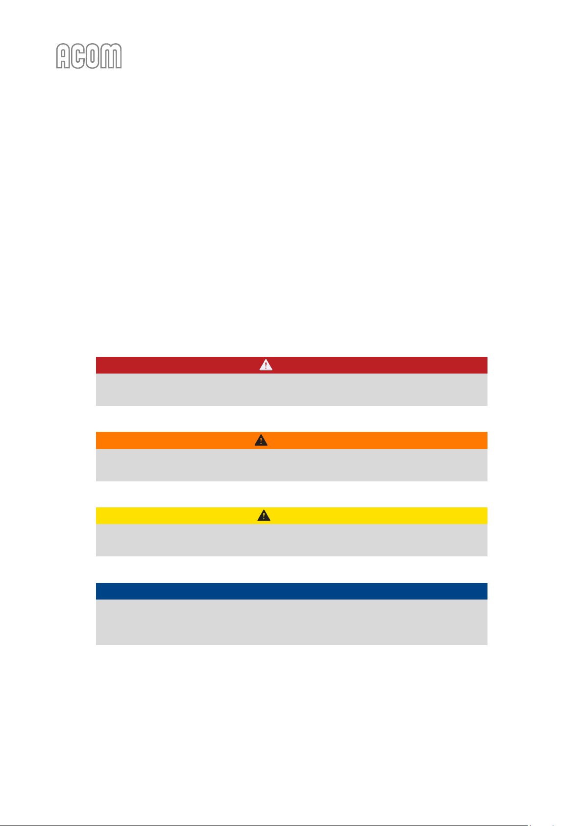
1.5. Safety Considerations, Explicit Definitions.................................................................................... 10
2. INSTALLATION.......................................................................................................................................... 13
2.1. Unpacking and Initial Inspection................................................................................................... 13
2.2. Line Voltage Selection................................................................................................................... 13
2.3. Amplifier Location Selection ......................................................................................................... 14
2.4. Connections................................................................................................................................... 15
2.5. Installation of External Fan (option).............................................................................................. 19
3. POWER ON, CONTROLS AND INDICATORS.............................................................................................. 20
4. OPERATION.............................................................................................................................................. 23
4.1. Turning ON and OFF...................................................................................................................... 23
4.2. Changing OPERATE and STANDBY Modes..................................................................................... 24
4.3. Antenna Change............................................................................................................................ 25
4.4. Tuning............................................................................................................................................ 25
4.5. Continuous Carrier Modes ............................................................................................................ 29
4.6. ON LINE Information Screens and Control Functions ................................................................... 30
4.7. Auto-Protection System................................................................................................................ 30
5. OFF LINE MODE ....................................................................................................................................... 32
5.1. Display Brightness Control ............................................................................................................ 32
5.2. Auto-Operate Enabling and Disabling........................................................................................... 32
5.3. Antenna Output Assignment......................................................................................................... 33
5.4. Reading Auto-protection Signatures............................................................................................. 33
6. MAINTENANCE ........................................................................................................................................ 34
6.1. Periodic Maintenance ................................................................................................................... 34
6.2. Cleaning......................................................................................................................................... 35

User's Manual | ACOM 1500 | HF + 6 m Linear Amplifier
Page 6of 52 | S e c t i o n ABOUT DOCUMENTATION
August 2021
6.3. Fuse Replacement......................................................................................................................... 35
6.4. Tube Replacement ........................................................................................................................ 37
6.5. Simplified Schematic Diagram....................................................................................................... 38
6.6. Troubleshooting ............................................................................................................................ 40
7. SPECIFICATIONS....................................................................................................................................... 42
7.1. Parameters.................................................................................................................................... 42
7.2. Functions....................................................................................................................................... 44
7.3. Storage and Shipment................................................................................................................... 45
7.3.1. Storage Environment....................................................................................................... 45
7.3.2. Shipping Size and Weight ................................................................................................ 45
7.3.3. Transportation................................................................................................................. 45
7.3.4. Returning to the Service Provider ................................................................................... 45
7.4. Information on Disposing and Recycling of Old Electrical and Electronic Equipment.................. 46
NOTES.............................................................................................................................................................. 47
Figures
Figure 2-1 Rear panel - Connections ............................................................................................................... 15
Figure 2-2 External fan .................................................................................................................................... 19
Figure 3-1 Front panel - Display and Controls................................................................................................. 20
Figure 3-2 Information screens and control functions structure.................................................................... 21
Figure 4-1 Using TRI tuning aid........................................................................................................................ 28
Figure 6-1 Simplified schematic diagram ........................................................................................................ 39
Figure 7-1 Packaging cardboard box ............................................................................................................... 45
Tables
Table 2-1 Amplifier individual data ................................................................................................................. 13
Table 4-1 Approximate tuning presets............................................................................................................ 27

User's Manual | ACOM 1500 | HF + 6 m Linear Amplifier
August 2021
S e c t i o n GENERAL INFORMATION | Page 7of 52
1. GENERAL INFORMATION
Congratulations on purchasing one of the finest HF amplifiers in the world today.
ACOM is pleased that you have chosen one of our products, and we will endeavor to provide you with the
information and support you need to enjoy your purchase for many years.
We urge you to read all of the following materials before you embark on operating your new amplifier.
1.1. Introduction and Description
This manual explains:
•Installation
•Operation and
•Maintenance
of the ACOM 1500 HF + 6 meter linear amplifier.
The ACOM 1500 is a complete and self-contained linear amplifier that covers all amateur bands from 1.8
through 54 MHz and provides over 1500 W PEP (1200 W continuous carrier) output power with less than
85 W exciter drive. Antenna SWR up to 3:1 is acceptable with 1200 W forward power. Tuning is
substantially simplified by a plate-load True Resistance Indicator (TRI) and by an automatically controlled
input attenuator. Operating parameters are displayed by a multi-functional high brightness OLED display.
Full break-in transmit/receive switching (QSK) is standard.

User's Manual | ACOM 1500 | HF + 6 m Linear Amplifier
Page 8of 52 | S e c t i o n GENERAL INFORMATION
August 2021
1.2. Owner Assistance
If assistance is needed, you should contact your local dealer first. If necessary, your dealer will contact ACOM
for additional guidance.
If you still have an issue you need to discuss with one of ACOM's specialists, the contact information is as
follows:
ACOM Ltd.
E-mail: support@acom-bg.com
Bulgaria | Bozhurishte 2227
Sofia-Bozhurishte Economic Zone | 6 Valeri Petrov Str.
GPS coordinates: 42.748616о| 23.209801о
1.3. Equipment Supplied
The ACOM 1500 amplifier and this User's Manual are shipped in a cardboard carton.
1.4. Features
•Easy to operate
The TRI (True Resistance Indicator) is a powerful tuning aid which, together with the automatically
controlled input attenuator, helps the operator to quickly and precisely match the antenna impedance
to the optimum tube load impedance (5-10 seconds typically). The auto-operate function (when
enabled) maintains the amplifier in the OPERATE mode for you, thus saving manual operations and
time.
•No antenna tuner needed
No heavy outboard antenna tuners required for antenna SWRs up to about 3:1. Your amplifier will
enable you to change antennas virtually instantaneously and allow you to use your antennas over
wider frequency ranges.
•User-friendly and durable
An amplifier that is both user-friendly and that looks after itself. It is designed to safely withstand up
to 300 W reflected power, up to 100 milliseconds duration of drive spikes, drive RF "tails" after a PTT
or KEY release, operator's inadvertent tuning errors etc. The amplifier also will not cease to function
with a "soft" AC mains and will deliver more than half power at only 85% of nominal mains voltage. It
can withstand voltage drops (down to zero Volts) for up to 10 milliseconds and can tolerate 15% mains
voltage spikes, which is especially important on Field Day, during DXpeditions, and at portable
operating events where emergency power is relied upon.
•OLED comment display
All amplifier status indications are explained via detailed text displayed on the OLED (Organic Light
Emitting Diode) Display. The upper line on the OLED display always reads peak forward power. LED
indicators are provided for: OPERATE mode, attenuation-on (ATT), transmit (TX), selected antenna
output (1, 2, or 3), and ON/OFF conditions.
•Easy antenna selection
Three antenna outputs are selectable using a push-button on the front panel.

User's Manual | ACOM 1500 | HF + 6 m Linear Amplifier
August 2021
S e c t i o n GENERAL INFORMATION | Page 9of 52
•Easy maintenance
Signatures of the amplifier internal status are stored in a nonvolatile memory for 7 most recent auto
protection trips. This information can be forwarded to your dealer for diagnostics. Using an EXCEL
application (available from ACOM or your dealer free of charge) and a PC you can decode the
signatures by yourself, too.
•Less noise in the shack
The input bypassing and the vacuum antenna relays are virtually silent even in the QSK CW mode due
to their special mounting.
•Efficient tuning
Less QRM and improved Electro Magnetic Compatibility during tuning. Amplifier tuning can be
achieved in less than 10 seconds at a quarter of nominal output power.
•Transceiver-independent
The amplifier operates without special signals from the transceiver - "Ground on TX" (PTT) and 85 W
RF drive power are sufficient.
•Broadband input matching
Broadband input matching circuit design provides excellent transceiver loading over the entire
spectrum, from 1.8 MHz up to 54 MHz.
•Single tube operation
Uses a single 4CX1000A/8168 ceramic and metal radial beam tetrode with plate dissipation of 1000 W
(forced air cooled, grid-driven), which is specifically designed for class AB1 RF linear amplifier
operation.
•Tube protection
Permanent monitoring includes protection of plate and grid voltages and currents, as well as exhaust
air temperature. The Bias Optimizer decreases the heat dissipated from the tube, and there is
automatic protection against overheating in accordance with specifications of the tube manufacturer.
•Output RF arc protection
Output RF arc protection is employed. This important feature safeguards the amplifier, antenna,
antenna selector, and tuner against severe damage in case of possible breakdown.
•High voltage protection
High voltage power supply inrush current limitation. This feature reduces the risk to sensitive devices
connected to the same mains circuit (important when used portable) when the amplifier is turned on.
Moreover, the amplifier can be configured for 8 different nominal line voltages: 100, 110, 120, 200,
210, 220, 230, or 240 VAC, 50 or 60 Hz.
•Continuous monitoring and/or selectable measurement
Continuous monitoring and/or selectable measurement of the 12 most important parameters of the
amplifier, exciter, and the selected antenna via the OLED display.

User's Manual | ACOM 1500 | HF + 6 m Linear Amplifier
Page 10 of 52 | S e c t i o n GENERAL INFORMATION
August 2021
1.5. Safety Considerations, Explicit Definitions
The ACOM 1500 HF + 6 meters Linear Amplifier is a Safety Class I unit regarding protection against electric
shock. The third grounding lead of its mains cord (colored yellow with two green stripes) and the ground
stud on the rear panel of the amplifier (marked GND, see Figure 2-1 Rear panel - Connections, Pos. (a)) must
be connected to the station's grounding system for safe operation.
The amplifier is designed to meet international safety standards and complies with CE safety and
electromagnetic compatibility requirements, as well as FCC regulations.
This User's Manual contains information, warnings (signal words Danger, Warning, Caution and Notice) and
instructions, related to hazards, that should be followed by the user in order to ensure safe operation and
to keep the amplifier in a safe working condition at all times.
The EXPLICIT DEFINITIONS described below apply to this User's Manual:
DANGER
These notes call attention to a procedure or instructions which, if not correctly
performed, will result in serious personal injuries and even death.
WARNING
These notes call attention to a procedure or instructions which, if not correctly
performed, could result in serious personal injuries and even death.
CAUTION
These notes call attention to a procedure or instructions which, if not correctly
performed, could result in minor or moderate personal injuries.
NOTICE
These notes call attention to a procedure or instructions which, if not correctly
performed, could result in property damage or equipment damage not exclusively to
the amplifier but also to connected equipment.

User's Manual | ACOM 1500 | HF + 6 m Linear Amplifier
August 2021
S e c t i o n GENERAL INFORMATION | Page 11 of 52
Information notes described below apply to this User's Manual:
These notes highlight operating procedures or practices that may improve equipment
reliability and/or personnel performance, or to emphasize a concept.
ORANGE TEXT as LINKS
marks all internal links in the document between Sections, Figures, Tables, etc. for your
convenience.
The safety instructions contained in this User's Manual feature specific signal words
(Danger, Warning, Caution or Notice) and, where required, a safety alert symbol, in
accordance with actual standards ISO 3864 or ANSI Z535.

User's Manual | ACOM 1500 | HF + 6 m Linear Amplifier
Page 12 of 52 | S e c t i o n GENERAL INFORMATION
August 2021
PRECAUTIONS:
DANGER
The amplifier works with high voltages up to 3000 V, which are LETHAL!
For your safety, pull the amplifier power plug out of the mains wall outlet and WAIT AT
LEAST 30 minutes EACH TIME BEFORE you remove the cover of the amplifier. Do not
touch any part inside while the amplifier is open because some residual voltages may
still be present.
DANGER
Never allow anyone, ESPECIALLY CHILDREN, to push or put anything into holes in the
case - this will cause electric shock. NEVER TOUCH AN ANTENNA or antenna insulators
during transmission or tuning - this may result in an electric shock or burn. NEVER
EXPOSE the amplifier to rain, snow or any liquids. AVOID placing the amplifier in
excessively dusty environments or in direct sunlight. DO NOT OBSTRUCT AIR INTAKE
(rear panel) and EXHAUST (top cover) areas of the amplifier. Keep a minimum clearance
distance of 10 cm (4 inches) to the intake and 50 cm (20 inches) above the exhaust
opening.
WARNING
Do not undertake on your own repairs or changes in hardware or software of the
amplifier in order not to endanger your or other's health and life and not to damage the
amplifier and the equipment connected with it, not covered by warranty. The
manufacturer is not liable for another's actions and responsibility shall be assumed by
the doer.
WARNING
To avoid damage (not covered under warranty) read the Section 2 INSTALLATION of this
User's Manual carefully. If you have any doubts about the installation, operation or
safety of the amplifier, please, consult your dealer.

User's Manual | ACOM 1500 | HF + 6 m Linear Amplifier
August 2021
S e c t i o n INSTALLATION | Page 13 of 52
2. INSTALLATION
2.1. Unpacking and Initial Inspection
Before you install your amplifier, thoroughly read this manual.
First, carefully inspect the cardboard carton and its contents for physical damage.
ACOM ships amplifiers in highly protected containers, but it cannot assure that
mistreatment by shippers will not occur. If damage is evident, notify your dealer
immediately. Delay may void the carrier's warranty.
Keep all packing materials for possible future amplifier shipment (see Section 7.3.4 Returning to the Service
Provider).
2.2. Line Voltage Selection
NOTICE
In order to avoid any damage (not covered by the warranty), check carefully to be
certain that the voltage for which the amplifier is set corresponds to your mains nominal
voltage.
Normally, the amplifier is supplied set for a nominal line voltage of 240 V. If your mains voltage is not 240 V,
you must contact your dealer for instructions. The only exception to this is if the unit has been custom
ordered, in which case the voltage selection will be noted in the Table of Individual Data (see Table 2-1
Amplifier individual data).
Table 2-1 Amplifier individual data
AMP SN:
Tube SN:
Voltage Selector Position
VAC
Table 2-1 Amplifier individual data
The amplifier power supply can be configured for 8 different nominal line voltages:
100, 110, 120*, 200, 210, 220, 230, or 240 VAC, 50 or 60 Hz.
*Note the limitation for 100/120 VAC operation in Sections 7.1.b) Power Output and 7.1.i)
Mains Power Consumption.

User's Manual | ACOM 1500 | HF + 6 m Linear Amplifier
Page 14 of 52 | S e c t i o n INSTALLATION
August 2021
2.3. Amplifier Location Selection
CAUTION
The weight of the unit is about 26.5 kg (58.5 lbs.), which should preferably be handled
by two persons.
Position the amplifier near the place where it will be used. You will need an easy access to the command
knobs and indicator's area, as well as to the rear panel cabling.
No magnetic-field sensitive devices (such as microphones) should be located next to the right side of the
amplifier because its power transformer is located there. It is advisable to position the amplifier to the right
of your transceiver.
No temperature-sensitive devices should be located above the exhaust hot air area. This means that the
amplifier should not be located under a shelf or other structure that could impede the free movement of
air away from the amplifier. You may prefer to use the bottom scales of both variable capacitor knobs
(TUNE and LOAD) if you install it on a shelf.
NOTICE
Do not under any circumstances obstruct the air intake (rear panel) or exhaust (top
cover) areas of the amplifier. Keep a minimum clearance distance of 10 cm (4 inches)
from the intake and 50 cm (20 inches) from the exhaust openings.
NOTICE
Do not leave accidental paper, cloth or other lightweight pieces around and under the
amplifier. They may be drawn in by the cooling air stream and block the vents. This will
lead to overheating and accelerated material aging, not covered by the warranty.

User's Manual | ACOM 1500 | HF + 6 m Linear Amplifier
August 2021
S e c t i o n INSTALLATION | Page 15 of 52
2.4. Connections
Please, see Figure 2-1 Rear panel - Connections.
Connection to your station must be accomplished in the order described below, before you apply mains
voltage to the amplifier.
Before you connect the amplifier to external grounding, you should advise with a
licensed electrician and confirm such kind of connection is allowed by your national and
local electrical code, safety rules, and regulations in force. Simultaneous connection to
the earth grounding and protective earth may be inadmissible or may fall under special
requirements in some countries!
DANGER
Never use the gas installation for grounding. This can cause an EXPLOSION!
DANGER
Do not use the steam-heating or water-supply network for grounding! You may exposе
to dangerous voltage not only yourself but also other people using the same installation.
Figure 2-1 Rear panel - Connections
a)
c)
d)
e)
g)
1
2
f)
b)

User's Manual | ACOM 1500 | HF + 6 m Linear Amplifier
Page 16 of 52 | S e c t i o n INSTALLATION
August 2021
a) GND stud
First, connect the wing-nut ground stud of the amplifier (on the rear panel, marked GND) to the station's
grounding system (see Figure 2-1 Rear panel - Connections, Pos. (a)).
WARNING
Note that the grounding system may have to withstand currents over 20 A with
insignificant voltage drop on it. Therefore, it may be necessary to improve it
considerably, i.e., to become less resistive, with heavier leads and lower-resistive ground
path. The grounding leads should be at least 8 mm² (AWG 8 or SWG 10).
b) RF INPUT socket
Connect a suitable coaxial cable from the transceiver output to the amplifier RF INPUT SO-239 socket (see
Figure 2-1 Rear panel - Connections, Pos. (b)), using PL-259 plug.
NOTICE
In order to avoid a damage, turn off your transceiver's internal antenna tuner.
c) ANTENNA 1, ANTENNA 2, and ANTENNA 3 sockets
NOTICE
If this is the first time you will use a power amplifier in your station, pay attention to the
coaxial cable type from the amplifier's three outputs to the antennas. It must handle the
increased power safely, particularly on the 10- and 6 meters bands. We recommend that
you use RG213 cable or better. Check the same for the antenna selector and tuner as
well as the antenna system.
Connect a suitable coaxial cable with a PL-259 plug (with PTFE insulation) from the appropriate amplifier
output (marked ANTENNA 1, ANTENNA 2, and ANTENNA 3, see Figure 2-1 Rear panel - Connections, Pos. (c))
to the antenna selector or tuner, or to the antenna for the respective frequency band.
d) KEY-IN socket
This is the amplifier's input for receive/transmit control from the transceiver.
The transceiver controls the amplifier from receive mode into transmit mode (RX/TX) by grounding of the
KEY-IN input.

User's Manual | ACOM 1500 | HF + 6 m Linear Amplifier
August 2021
S e c t i o n INSTALLATION | Page 17 of 52
Run a shielded cable from the "ground on transmit" socket or terminal on your transceiver to the amplifier
KEY-IN socket (see Figure 2-1 Rear panel - Connections, Pos. (d)). The KEY-IN socket uses a standard RCA
phono plug.
The switching voltage presented from amplifier KEY-IN socket to the transceiver
"ground on transmit" output does not exceed 14 V (positive to the ground). The closed-
circuit current is below 8 mA.
Your amplifier will not work if KEY-IN input is not connected properly.
Transceiver producers give different names to this output and they are for instance
TX-GND, SEND, T/R-LINE, PTT, etc. Some transceivers require that "ground on transmit"
is implemented via a software command, or by changing the setting of a switch on the
rear panel, or interior of the transceiver. Check your transceiver's manual.
e) KEY-OUT socket
This is the amplifier's transmit-enabling control output to the transceiver.
The KEY-OUT socket (see Figure 2-1 Rear panel - Connections, Pos. (e)) provides an extra control signal from
the amplifier to the transceiver. It could be used to improve the transmit/receive (RX/TX) switching safety.
NOTICE
KEY-OUT is a low-power open-drain output, make sure that the signal voltage coming
from the respective transceiver connection does not exceed 50 VDC (open circuit) and
the closed-circuit current is below 20 mA.
If your transceiver has a suitable input that disables transmission unless grounded externally, we
recommend that you connect it with a shielded cable terminated in a Phono (RCA) connector to the
KEY-OUT socket of the amplifier.
ACOM 1500 will operate normally with KEY-OUT unconnected if your transceiver has no
such input.
Transceiver producers give different names to this input and they are for instance
TX-INHIBIT, MUTE, LINEAR, etc. Check your transceiver's manual.

User's Manual | ACOM 1500 | HF + 6 m Linear Amplifier
Page 18 of 52 | S e c t i o n INSTALLATION
August 2021
f) Main fuses
NOTICE
Make sure you check whether the main fuses installed in your amplifier (see Figure 2-1
Rear panel - Connections, Pos. (f)) correspond to your local mains nominal voltage and if
necessary, replace them as described in Section 6.3 Fuse Replacement!
WARNING
If your amplifier is only fitted with one line (mains) fuse, it is suitable for European
Community ONLY. Your dealer will check that your amplifier is correctly fused before it is
shipped to you. Customers should check with a qualified electrician if the amplifier is to
be used outside the country in which it was purchased.
g) Power cord
Due to the different standards in different countries, the mains plug is supplied and mounted by the dealer.
He connects to the mains cord end (see Figure 2-1 Rear panel - Connections, Pos. (g)) a standard mains supply
plug which meets the Safety Class I unit standard in your country.
The ground lead of the amplifier's power cord is colored yellow with two green stripes and the blue and
brown leads are active. When the amplifier is to be used with only one mains fuse, it is connected in series
with the brown lead, which must be the active. If you have any doubts about the correct way of connecting
the wires, consult your dealer.
h) Preparation of wall outlet
WARNING
Before connecting the amplifier to your mains supply using a licensed electrician, check
that the supply is correctly wired, and is adequate for power consumption up to
3500 VA. Make certain that the grounding lead is connected properly and that it has a
cross section not less than the cross section of the phase conductor in the wall outlet for
the amplifier.
It is preferable that you use the wall outlet closest to the source. The installation leads should be at least
2.5 mm² (AWG 13 or SWG 15) at operating 200-240 VAC or 100-120 VAC, (recommended values if there are
no stricter requirements by your local standard).
Check that the panel fuse has a free capacity for the additional load from the amplifier as specified in
Sections 6.3 Fuse Replacement and 7.1.i) Mains Power Consumption.If you connect the amplifier to a different
mains outlet, be sure that you check it, too.

User's Manual | ACOM 1500 | HF + 6 m Linear Amplifier
August 2021
S e c t i o n INSTALLATION | Page 19 of 52
Make sure the main Power Switch (marked "LINE", see Figure 2-1 Rear panel - Connections, Pos. (2)), on the
rear panel is in OFF position and insert amplifier's mains plug into the wall outlet prepared for it. The
amplifier remains switched off.
2.5. Installation of External Fan (option)
This fan (see Figure 2-2 External fan) is not necessary in SSB and CW modes, nor in continuous carrier modes
(RTTY, SSTV, etc.) with carrier down times of maximum 15 minutes and a subsequent pause of 3 minutes.
For higher duty cycles such as continuous broadcast or increased ambient temperatures the fan is
recommended. The auxiliary fan (92x92 mm) must be brushless type, 2...5 W, 24 VDC. It may be installed by
your dealer or by the manufacturer on request.
Figure 2-2 External fan

User's Manual | ACOM 1500 | HF + 6 m Linear Amplifier
Page 20 of 52 | S e c t i o n POWER ON, CONTROLS AND INDICATORS
August 2021
3. POWER ON, CONTROLS AND INDICATORS
NOTICE
Do not turn the amplifier on for at least 2 hours after unpacking it in the room where it
will be used. Pay particular attention when you move it from a very cold into a warm
place - condensation is likely and this could result in damage to the high voltage circuits.
In such a case, wait at least 4 hours. A similar effect can occur after a rapid warming of
the operating room (for instance after switching on a powerful heater in a cold shack).
NOTICE
In order to avoid any damage (not covered by the warranty), check carefully to be
certain that the voltage for which the amplifier is set corresponds to your mains nominal
voltage (see Section 2.2 Line Voltage Selection and Table 2-1 Amplifier individual data).
After following all instructions in Section 2 INSTALLATION, you may turn on the main power switch (marked
"LINE") on the rear panel (see Figure 2-1 Rear panel - Connections, Pos. (2)). The LED indicator above the
POWER button (located on the front panel) must light red and "ACOM 1500" will appear on the display (see
Figure 3-1 Front panel - Display and Controls).
Figure 3-1 Front panel - Display and Controls
You will note that the upper line of the display always reads the peak forward power, even in STBY mode.
The scale resolution is 15 W per bar. Note also that levels below 20 W may be not detected.
In this position (called OFF LINE hereafter), only the micro-controller is operational, while the amplifier
itself is still turned off (and the tube is not powered at all).
Other manuals for 1500
3
This manual suits for next models
1
Table of contents
Other Acom Amplifier manuals