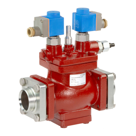
Acorn Engineering SFST-T-OT-ITG Manual

INSTALLATION, OPERATION AND MAINTENANCE INSTRUCTIONS
SFST THERMOSTATIC MIXING VALVE SUPPLY FIXTURE
NOTES TO THE INSTALLER:
1. Please leave this documentation with the owner of the fixture when finished.
2. Please read this entire booklet before beginning the installation.
3. Check your installation for compliance with plumbing and other applicable codes.
LIMITED WARRANTY
UNITED STATES AND CANADA
Acorn Controls warrants that its products are free from defects in material or workmanship under normal use and
service for a period of one year from date of shipment. Acorn's liability under this warranty shall be discharged solely
by replacement of repair of defective material, provided Acorn is notified in writing within one year from date of
shipment, F.O.B. Industry, California.
This warranty does not cover installation or labor charges and does not apply to materials, which have been
damaged by other causes such as mishandling or improper care or abnormal use. The repair or replacement of the
defective materials shall constitute the sole remedy of the Buyer and the sole remedy of Acorn under this warranty.
Acorn shall not be liable under any circumstances for incidental, consequential or direct charges caused by defects in
materials, or any delay in the repair or replacement thereof. This warranty is in lieu of all other warranties expressed
or implied. Product maintenance instructions are issued with each unit and disregard or non-compliance with these
instructions will constitute an abnormal use condition and void the warranty.
FOR TECHNICAL ASSISTANCE
1.800.743.8259
fieldservice@acorneng.com
Date: 09/22/17
Model SFST Series
Patent Pending
WWW.ACORNENG.COM
ACORN ENGINEERING COMPANY
P.O. BOX 3527
CITY OF INDUSTRY, CA 91744
UNITED STATES OF AMERICA
Acorn Controls Division of Acorn Engineering Company®, A member of Morris Group International™
Federal
Public Law
111-380
(No Lead)
Manual #7802-117-000

Page 2 of 8
SFST Installation & Operation Manual
You are required to thoroughly read all installation
instructions and product safety information before
beginning the installation of this product.
FAILURE TO READ AND FOLLOW PROPER
INSTALLATION AND MAINTENANCE
INSTRUCTIONS MAY RESULT IN PRODUCT
FAILURE WHICH CAN CAUSE PROPERTY
DAMAGE, PERSONAL INJURY AND/OR
DEATH.
Acorn Controls is not responsible for damages
resulting from improper installation and/or
maintenance. Installation of this valve shall be in
accordance with Uniform Plumbing Code.
TO ENSURE ACCURATE AND RELIABLE
OPERATION OF THIS PRODUCT, IT IS
ESSENTIAL TO:
ŸProperly design the system to minimize
pressure and temperature variations.
ŸImplement an annual maintenance program
to ensure proper operation and temperature
setting of valve(s).
ŸThis valve is factory preset. However, it can
be adjusted. It is the responsibility of the
installer and or facility maintenance personnel
to make sure valve outlet temperature does
not exceed 115°F (46°C) after installation,
maintenance or repair.
(Not provided by Acorn)
1. Wall anchors, screws nuts and washers as
required.
2. Lead free solder and flux for sealing water
connections.
3. Pipe fittings.
4. 5/8” wrench and 1/8” Allen wrench.
Flush supply lines of all foreign material such as
Ÿ
pipe dope, chips or solder prior to connecting to
mixing valve.
To ensure proper installation, review the Manual
Ÿ
thoroughly to verify rough-ins before beginning
any work.
Installation and field adjustment are the
Ÿ
responsibility of the installer.
Maximum water pressure is 125 psi (8.62 bars).
Ÿ
Maximum inlet hot water temperature is 180°F
(82°C). Temperature adjustment range* is
90°C-115°F (32°C-46°C). Valve assembly must
be drained prior to being subjected to freezing
temperatures. Valve includes integral check
valves.
PRESSURE
DROP 10
(69)
5.7
(21.4)
15
(103)
7
(26.2)
20
(138)
8
(30.2)
30
(207)
9.8
(37)
45
(310)
12
(45.4)
60
(414)
13.8
(52.4)
5
(34)
4
(15)
FLOW RATE
GPM (LPM)
PSID (kPa)
Cv
1.8
*In accordance with ASSE 1070 and ASSE 1069
WARNING:
!
SUPPLIES REQUIRED:
Acorn Controls Division of Acorn Engineering Company®, A member of Morris Group International™
!IMPORTANT
Manual #7802-117-000 Date: 09/22/17

Page 3 of 8
NOTE;
ALL DIMENSIONS ARE IN INCHES (MM).
ROUGH-IN DIMENSIONS:
Acorn Controls Division of Acorn Engineering Company®, A member of Morris Group International™
SFST Installation & Operation Manual
SFST-T-OT-ITG SFST-B-OB-ITG
SFST-B-OT-ITG SFST-B-OSL-ITG
127
8"
(327)
13"
(330)
73
4"
(197)
105
8"
(270)
13"
(330)
73
4"
(197)
77
8"
(200)
41
4"
(108)
73
4"
(197)
15"
(381)
15"
(381)
73
4"
(197)
Manual #7802-117-000 Date: 09/22/17

Page 4 of 8
NOTE;
ALL DIMENSIONS ARE IN INCHES (MM).
ROUGH-IN DIMENSIONS:
Acorn Controls Division of Acorn Engineering Company®, A member of Morris Group International™
SFST Installation & Operation Manual
41
4"
(108)
16"
(406)
73
4"
(197)
73
4"
(197)
16"
(406)
73
4"
(197)
73
4"
(197)
131
2"
(343)
105
8"
(270)
13
4"
(44)
8"
(203)
145
8"
(371)
131
2"
(343)
73
4"
(197)
73
4"
(197)
65
8"
(168)
SFST-B-OB-CWB-ITG SFST-T-OT-CWB-ITG
SFST-B-OSL-CWB-ITG SFST-B-OT-CWB-ITG
127
8"
(327)
Manual #7802-117-000 Date: 09/22/17

Page 5 of 8
1. Locate mixing valve fixture in a suitable place
accessible for servicing and adjusting. Valve
fixture should be as close as possible to point
of use.
2. Thoroughly flush supplies.
3. Connect Hot and Cold supplies to mixing valve
inlets and outlet to fixture(s). Valve fixture
connections are 1/2” NCT, for supply lines
by others.
4. Turn on supplies and inspect for leaks. Tighten
connections if leak(s) are detected.
5. Turn on fixture and allow to run until water
temperature stabilizes. Measure water
temperature. If water is not at desired
temperature adjust as needed, (refer to
adjustment section below). Maximum
recommended outlet temperature is 115°F
(46°C).
1. Loosen locknut. Detail A
2. Turn on fixture so temperature can stabilize.
3. Using 1/4” allen wrench turn adjustment stem
counter-clockwise for hotter or clockwise for
colder outlet temperature. Detail B
4. Tighten locknut to prevent any unauthorized
or accidental temperature adjustment.
5. Re-check temperature.
INSTALLATION:
TEMPERATURE ADJUSTMENT:
Acorn Controls Division of Acorn Engineering Company®, A member of Morris Group International™
SFST Installation & Operation Manual
DETAIL A DETAIL B
LOCKNUT
5/8" WRENCH
1/8" ALLEN
WRENCH
ADJUSTMENT
STEM
TYPICAL INSTALLATION
INSTALLER
PROVIDED
1/2” NCT RISER,
SUPPLIES AND
CONNECTIONS
Manual #7802-117-000 Date: 09/22/17

Page 6 of 9
CAUSE SOLUTIONPROBLEM
1. SET POINT DIFFICULT TO SET OR
CANNOT BE REACHED
SUPPLY TEMPS NOT WITHIN
SPECIFIED LIMITS
HOT AND COLD SUPPLIES ARE
REVERSED
CHECK DIFFERENTIAL TEMPERATURE
BETWEEN SUPPLIES AND OUTLET
REINSTALL VALVE WITH SUPPLIES
CONNECTED TO MARKED INLETS
2. DOES NOT MAINTAIN OUTLET
TEMPERATURE OR CHANGES
FLUCTUATION IN SUPPLY
PRESSURES
CHECK VALVE/FILTERS BLOCKED
WITH DEBRIS
CHECK DIFFERENTIAL TEMPERATURE
BETWEEN SUPPLIES AND OUTLET
CLEAN CHECK VALVES/FILTERS
OVER TIME
3. DISCHARGE TEMPERATURE TOO
HOT OR TOO COLD
VALVE NOT ADJUSTED PROPERLY READJUST VALVE TEMPERATURE PER
INSTALLATION INSTRUCTIONS
4. CROSS FLOW CHECK VALVES FOULED CLEAN CHECK VALVES/FILTERS
5 NO FLOW FROM VALVE HOT OR COLD SUPPLY FAILURE
OR SHUTOFFS CLOSED
OPEN SHUTOFFS OR RESTORE HOT
AND COLD SUPPLIES
CHECK VALVE/FILTERS BLOCKED
WITH DEBRIS
CLEAN CHECK VALVES AND FILTERS
COLD
WATER
SUPPLY
TYPICAL 1069 APPLICATION PIPING DETAIL
ST7069
HOT
WATER
SUPPLY
COLD
WATER
SUPPLY
TYPICAL 1070 APPLICATION PIPING DETAIL
ST7069 HOT
WATER
SUPPLY
Valve Specifications:
Maximum Operating Pressure: .................. 125 PSI (862 kPa)
Maximum Hot Water Supply Temp: .................... 180°F (82°C)
Minimum Hot Water Supply Temp.**: ................... 10° F (6° C)
Above Set Point
Outlet Temp. Range*: ....................... 90°F-115°F (32°C-46°C)
Flow Rate: ................ 12 GPM (45 LPM) @ 45 PSI (310 kPa)
Differential
Minimum Flow*: ........................................ 0.5 GPM (1.9 LPM)
*In accordance with ASSE 1070 and ASSE 1069
**Inlet Supply Pressure Variation Up to 20%
TROUBLESHOOTING:
PIPING DETAILS:
Acorn Controls Division of Acorn Engineering Company®, A member of Morris Group International™
SFST Installation & Operation Manual
Manual #7802-117-000 Date: 09/22/17

A C O R N
RECIRCULATING PIPING DIAGRAM:
WATER
HEATER
C
C
T
T
EXPANSION
TANK
HIGH TEMPERATURE
HOT WATER FIXTURES
LOW TEMPERATURE
HOT WATER FIXTURES
HEAT
TRAP
CONTROL
VALVE
BALANCING
VALVE
LOW TEMP
FIXTURE
RETURN
HIGH TEMP
FIXTURE RETURN
T
C
CHECK VALVE
BALANCING VALVE
TEMP/PRESSURE GAUGE
CIRCULATOR
FLOW DIRECTION
CSELECT FLOW RATE NECESSARY TO ENSURE MIXING VALVE IS
OPERATING AT AN ASSE 1017 MINIMUM CERTIFIED FLOW RATE.
SEE LITERATURE.
COLD
WATER
SUPPLY
TYPICAL CONTINUOUS RECIRCULATION
WATER
HEATER
C
C
T
T
EXPANSION
TANK
HIGH TEMPERATURE
HOT WATER FIXTURES
LOW TEMPERATURE
HOT WATER FIXTURES
HEAT
TRAP
CONTROL
VALVE
BALANCING
VALVE
LOW TEMP
FIXTURE
RETURN
HIGH TEMP
FIXTURE RETURN
T
C
CHECK VALVE
BALANCING VALVE
TEMP/PRESSURE GAUGE
CIRCULATOR
FLOW DIRECTION
CSELECT FLOW RATE NECESSARY TO ENSURE MIXING VALVE IS
OPERATING AT AN ASSE 1017 MINIMUM CERTIFIED FLOW RATE.
SEE LITERATURE.
COLD
WATER
SUPPLY
TYPICAL RECIRCULATION WITH AQUASTAT
ADJUSTABLE
AQUASTAT
NOTE: TO BALANCE THE SYSTEM, BEGIN WITH DIVERTING 80% OF THE
RETURN WATER TO COLD SIDE OF THE TEMPERING VALVE (20% OF THE
HOT WATER SOURCE). CONTINUE ADJUSTING UNTIL SYSTEM IS FULLY
BALANCED.
A HEAT TRAP IS RECOMMENDED IF THE MIXING VALVE IS ABOVE THE
WATER HEATER.
NOTE: TO BALANCE THE SYSTEM, BEGIN WITH DIVERTING 80% OF THE
RETURN WATER TO COLD SIDE OF THE TEMPERING VALVE (20% OF THE
HOT WATER SOURCE). CONTINUE ADJUSTING UNTIL SYSTEM IS FULLY
BALANCED.
A HEAT TRAP IS RECOMMENDED IF THE MIXING VALVE IS ABOVE THE
WATER HEATER.
Page 7 of 8
Acorn Controls Division of Acorn Engineering Company®, A member of Morris Group International™
SFST Installation & Operation Manual
Manual #7802-117-000 Date: 09/22/17

Page 8 of 8
REPAIR PARTS:
Acorn Controls Division of Acorn Engineering Company®, A member of Morris Group International™
SFST Installation & Operation Manual
O-RINGS SHOULD BE LUBRICATED WITH AN NSF
APPROVED LUBRICANT. CARE SHOULD BE
EXERCISED WHILE INSERTING COMPONENTS
INTO VALVE BODY DURING REASSEMBLY.
!IMPORTANT
Manual #7802-117-000 Date: 09/22/17
NOTE:
Individual parts not available for purchase,
sold in repair kits only. Parts called out for
reference only.
7
10
11
12
13
14
16
17
18
19
VALVE BODY
SHOWN FOR
REFERENCE
15
ITEM DESCRIPTION
ADJUSTMENT STEM LOCK NUT5
VALVE BONNET6
BONNET O-RING7
ADJUSTMENT STEM8
ADJUSTMENT STEM O-RING9
SHUTTLE O-RING
10
SHUTTLE
11
ITEM DESCRIPTION
12
THERMOSTATIC MOTOR13
LOWER SPRING
14
INLET SCREEN (x 2)
15
CHECK VALVE (x 2)
16
CHECK VALVE BONNET O-RING (x 2)
17
CHECK VALVE BONNET (x 2)
18
FUNNEL
UPPER SPRING
19
KIT NUMBER DESCRIPTION
COMPLETE REBUILD KIT7803-500-001
INTERNAL REPAIR KIT7803-510-001
BONNET / STEM REPLACEMENT 7803-502-001
CHECK VALVR / STRAINER KIT7801-503-001
ITEM KIT NUMBER DESCRIPTIONITEM
1
2
3
4
ITEM DESCRIPTION
16
17
18
19
4
4
2
1
NOTE:
IF STEM 8 IS DAMAGED DURING REPLACEMENT
OF INTERNAL COMPONENTS KIT 3 WILL HAVE TO
BE ORDERED
5
6
7
8
9
3
This manual suits for next models
7
Table of contents
