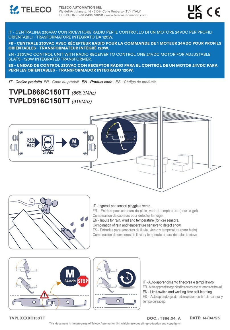
Teleco TVPLS868CS User manual

TELECO AUTOMATION SRL - Via dell’Artigianato, 16 - 31014 Colle Umberto (TV) ITALY
TELEPHONE: ++39.0438.388511 FAX: ++39.0438.388536 - www.telecoautomation.com
This document is the property of Teleco Automation Srl who reserves all reproduction and copying rights
IT - CENTRALE 24Vdc CON RICEVITORE RADIO PER IL COMANDO DI 1 MOTORE 24Vdc PER
PROFILI ORIENTABILI.
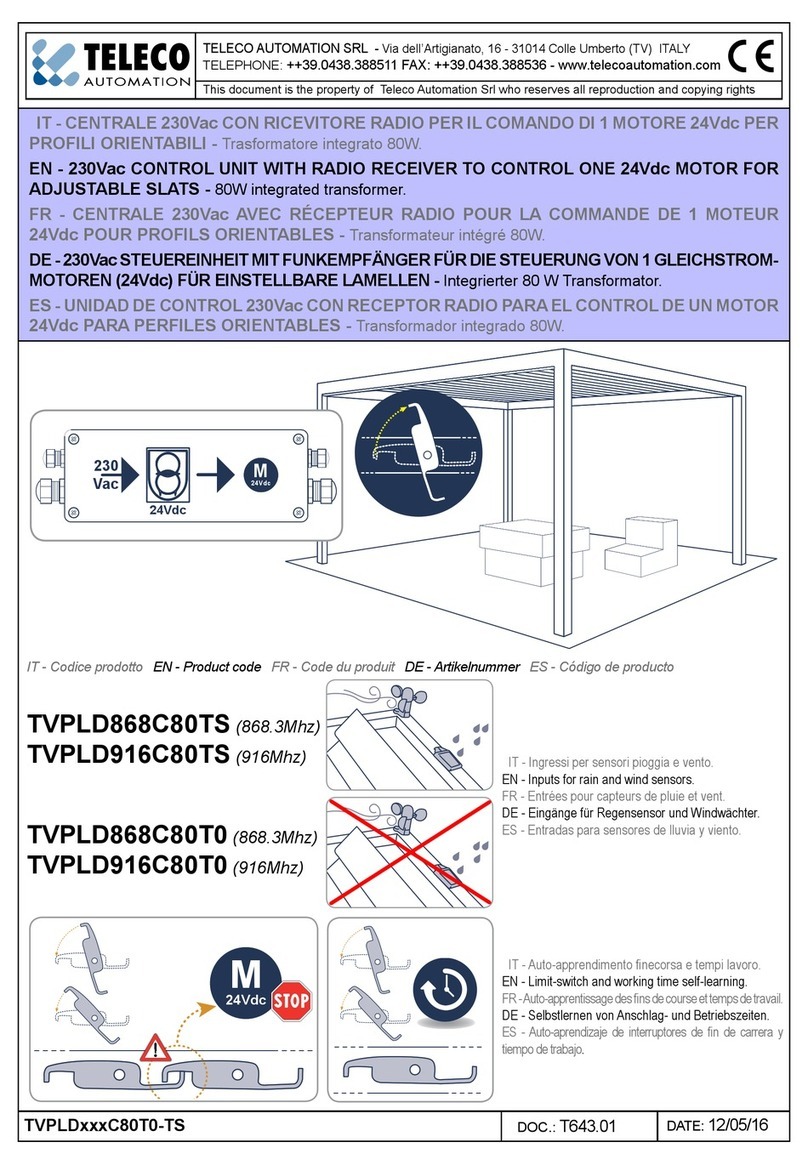
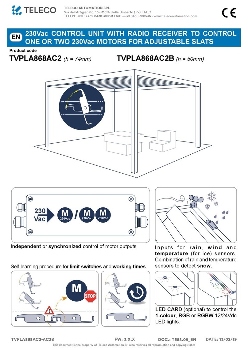
EN - 24Vdc CONTROL UNIT WITH RADIO RECEIVER TO CONTROL ONE 24Vdc MOTOR FOR
ADJUSTABLE SLATS.
FR - CENTRALE 24Vdc AVEC RÉCEPTEUR RADIO POUR LA COMMANDE DE 1 MOTEUR 24Vdc
POUR PROFILS ORIENTABLES.
DE - 24Vdc STEUEREINHEIT MIT FUNKEMPFÄNGER FÜR DIE STEUERUNG VON 1
GLEICHSTROM-MOTOREN (24Vdc) FÜR EINSTELLBARE LAMELLEN.
ES - UNIDAD DE CONTROL 24Vdc CON RECEPTOR RADIO PARA EL CONTROL DE UN MOTOR
24Vdc PARA PERFILES ORIENTABLES.
IT - Ingressi per sensori pioggia e vento.
EN - Inputs for rain and wind sensors.
FR - Entrées pour capteurs de pluie et vent.
DE - Eingänge für Regensensor und Windwächter.
ES - Entradas para sensores de lluvia y viento.
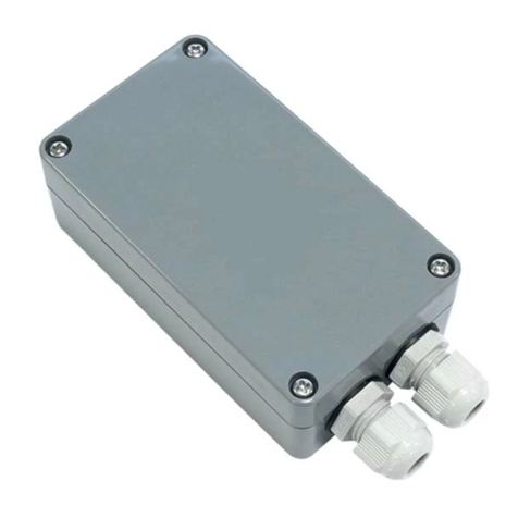
IT - Codice prodotto
EN - Product code
FR - Code du produit
DE - Artikelnummer
ES - Código de producto
IT - Auto-apprendimento necorsa e tempi lavoro.
EN - Limit-switch and working time self-learning.
FR - Auto-apprentissage des ns de course et temps de travail.
DE - Selbstlernen von Anschlag- und Betriebszeiten.
ES - Auto-aprendizaje de interruptores de n de carrera y tiempo de trabajo.
M
M
230Vac
IN
+ 24Vdc
-
+ 24Vdc
-
24Vdc
> 80W
Led
24Vdc
(< 4.5A)
IT - Uscita alimentazione 24Vdc
EN - 24Vdc power supply output
FR - Sortie de alimentation 24Vdc
DE - 24Vdc Stromversorgung Ausgang
ES - Salida de alimentación 24Vdc
M
24Vdc
DOC.: T661.01
TVPLSxxxCS DATE: 29/04/16
TVPLS868CS
(868.3Mhz)
TVPLS916CS
(916Mhz)

2
INDICE
1. Collegamenti e regolazioni p. 2
2. TRASMETTITORI p. 3 - 5
2.1 Memorizzazione codici radio
2.2 Congurazione del tempo lavoro (necessaria
se si usano trasmettitori 7/42 canali)
2.3 Cancellazione codici radio
2.4 Memorizzazione remota di ulteriori codici radio
2.5 Cancellazione remota di un codice radio
3. SENSORI p. 5
3.1 Sensore VENTO
3.2 Sensore PIOGGIA
4. Speciche tecniche p. 22
AVVERTENZE
Il prodotto in oggetto deve essere installato, messo in servizio e controllato periodicamente solo da personale tecnico
qualicato nel rispetto delle normative vigenti riguardanti le coperture automatiche. Il sistema è alimentato a 24Vdc. Prima
di collegare l’alimentazione assicurarsi che i sensori e i motori siano collegati correttamente. Un errato collegamento
(polarità discordi) potrebbe danneggiare i motori oltre che gli elementi meccanici ad essi collegati. L’alimentatore deve
fornire la tensione e la corrente richiesta dal dispositivo e dai motori collegati. L’alimentatore deve essere conforme
alla norma IEC60950-1 e protetto contro corto-circuiti e sovratensioni. Si consiglia l’uso di un cavo 2x1.5mm per
collegare i motori al dispositivo per una lunghezza no a 6m, mentre è opportuno un cavo 2x2.5mm per tratte superiori.
SMALTIMENTO DEL PRODOTTO: alla ne della vita utile, l’apparecchio non deve essere smaltito come riuto domestico, ma
conferito in un centro di raccolta riuti elettrici ed elettronici. Con la presente Teleco Automation s.r.l. dichiara che il prodotto è
conforme ai requisiti essenziali, ed alle altre disposizioni pertinenti, stabilite dalla direttiva 1999/5/CE. La dichiarazione di conformità
può essere consultata sul sito: www.telecoautomation.com/ce. Nell’ottica di un continuo sviluppo dei propri prodotti, il produttore
si riserva il diritto di apportare modiche a dati tecnici e prestazioni senza preavviso.
1Collegamenti e regolazioni
DIP1 DIP2 (A)
OFF OFF 1
OFF ON 2
ON OFF 3
ON ON 4
Default
FINECORSA. La centrale è in grado di arrestare i motori in corrispondenza
di un fermo meccanico, per assorbimento di corrente. La soglia può essere
impostata con DIP1 e DIP2 (tabella). Attenzione! Controllare che il motore
si fermi solo in corrispondenza dei necorsa (LM = ON): aumentare la soglia
se il motore si ferma durante la manovra o diminuire se il motore continua a
spingere sui fermi meccanici.
1ANTENNA GND
2ANTENNA RF
8SENSORE PIOGGIA (GIALLO, GND)
9SENSORE PIOGGIA (BLU, SEGNALE)
10 SENSORE PIOGGIA (BIANCO, +12V)
11 SENSORE VENTO (BLU)
12 SENSORE VENTO (MARRONE)
13 MOTORE (CHIUDE)
14 MOTORE (APRE)
15 ALIMENTAZIONE (+24Vdc)
16 ALIMENTAZIONE (GND)
17 USCITA ALIMENTAZIONE (GND)
18 USCITA ALIMENTAZIONE (+24Vdc)
AN LED IMPULSI SENSORE VENTO
RN LED SENSORE PIOGGIA ATTIVO
L1 ACCESO = ALLARME PIOGGIA
L2 LAMPEGGIANTE = ALLARME VENTO
LM LED FINECORSA
P1 TASTO DI PROGRAMMAZIONE Solo nella
versione “S”
IT
M
M
230Vac
IN
+ 24Vdc
-
+ 24Vdc
-
24Vdc
> 80W
Led
24Vdc
(< 4.5A)
AN
LED
-
+
14
13
L1 L2 LM
24Vdc IN
16
15
DIP SWITCH
P1
1
2
8
9
10
11
12
RN
LED
18
17
+
-24Vdc OUT
3
*Il buzzer emette un bip ad ogni pressione.
IT
Trasmettitore 7/42 canali
BCOMANDI AUTOMATICI (2 o 3 TASTI)
Trasmettitore 3/18 canali Trasmettitore 2 canali
A1 TASTO
2TRASMETTITORI
CHx
Funzioni:
APRE-STOP-CHIUDE
oppure
CHIUDE
CH1
CH2
CH3
CH4
CH5
CH6
CH7
Apertura (STOP)
Chiusura (STOP)
Apertura (STOP)
Chiusura (STOP)
Apertura
STOP
Chiusura
CH5
CH6
CH7
Apertura
STOP
Chiusura
CH1
CH2
CH3
CH4
CH5
CH6
CH7
0 % (CHIUSO)
50 %
70 %
100 % (APERTO)
Apertura (uomo presente)
STOP
Chiusura (uomo presente)
Apertura
(STOP)
Chiusura
(STOP)
Trasmettitore 7/42 canali
CTRASMETTITORE 7/42 CANALI
Premere il tasto P1 tante volte quante richieste dal tipo di memorizzazione desiderata e tenere premuto. Il buzzer emette un suono continuo.
Premere il tasto del trasmettitore relativo al codice da memorizzare. All’avvenuta memorizzazione il buzzer emette un suono intermittente.
TIPO DI MEMORIZZAZIONE P1
A1 TASTO: *
x1
Premere il tasto del trasmettitore
relativo al codice da memorizzare.
BCOMANDI AUTOMATICI (2 o 3 TASTI) *
x2
Premere il tasto del trasmettitore
relativo al codice da memorizzare.
A1 TASTO: *
x3
Premere il tasto del trasmettitore
relativo al codice da memorizzare.
CTRASMETTITORE 7/42 CANALI *
x4
Premere un tasto qualsiasi del
trasmettitore 7/42 canali.
TENUTO
...
suono
continuo
APRE STOP CHIUDE
CHIUDE
suono intermittente
2.1 Memorizzazione codici radio
P1

4
2.2 Congurazione del tempo lavoro (necessaria se si usano trasmettitori 7/42 canali)
Attenzione: la seguente procedura è indispensabile per poter utilizzare i trasmettitori a 7/42 canali (tipo C).
P1
*
x10
Comandare una
manovra con un
trasmettitore
memorizzato.
Premere nuovamente
P1 o attendere 25
secondi per uscire
dalla procedura senza
salvare.
Nota: è possibile interrompere questo ciclo automatico
con qualsiasi comando. Se viene superato il tempo lavoro
massimo (90 s) la centrale si ferma e suona in maniera
intermittente no alla pressione di un tasto qualsiasi.
(>3 s) suono intermittente
...
chiusura
completa
apertura
completa
...
LM lampeggia
apertura
completa
...
IT
P1
Premere il tasto P1 10 volte e tenere premuto per 3 secondi.
Il buzzer emette un suono intermittente.
*Il buzzer emette un bip ad ogni pressione.
2.3 Cancellazione codici radio
TIPO DI
CANCELLAZIONE P1
SINGOLO CODICE RADIO *
x5
Premere un tasto relativo al codice da
cancellare.
Premere 5 volte il tasto P1 e tenere premuto. Il buzzer emette un suono continuo. Il buzzer emette un suono intermittente. Premere un
tasto del trasmettitore relativo al codice da cancellare entro 10 secondi. All’avvenuta cancellazione il buzzer emette un suono continuo.
TUTTI I CODICI RADIO *
x6
Premere 6 volte il tasto P1 e tenere premuto per 10 secondi. Il buzzer emette un suono intermittente veloce. Rilasciare quando il suono
diventa costante.
TENUTO
(10 s)
suono
continuo
...
suono
intermittente
P1
suono
continuo
...

5
x 3
Cancellazione remota di un
codice radio
Nota: Il tasto P3 si trova all’interno del trasmettitore. Il codice radio aggiunto avrà le stesse funzioni del
codice usato per l’inserimento. La procedura è compatibile con qualsiasi tipo di trasmettitore.
Premere per il tasto P3 del trasmettitore già memorizzato. Il buzzer emette un suono
continuo. Premere il tasto relativo ad un codice memorizzato. Il buzzer si ferma per
1 secondo e riprende il suono continuo. Premere il tasto relativo al nuovo codice.
All’avvenuta memorizzazione il buzzer emette un suono intermittente veloce.
...
P3
< 5 s
suono
intermittente
Da cancellare
1 s
...
P3
Nuovo
< 5 s
suono
continuo
Memorizzato
< 5 s
suono
continuo
Memorizzato Memorizzato
Nota: Il tasto P3 si trova all’interno del trasmettitore.
Premere 3 volte il tasto P3 del trasmettitore memorizzato. Il buzzer emette un
suono intermittente lento. Premere il tasto relativo al codice da cancellare entro 5
secondi. All’avvenuta cancellazione il buzzer smetterà di suonare.
1.1
2.4 2.5
Memorizzazione remota di ulteriori codici radio
Sensore VENTO
(solo versione “S”)
1.1
3.1
L’anemometro (ANEM4) rileva la velocità del vento e la centrale la confronta con la soglia impostata tramite i DIP 3-4 (vedi tabella).
La centrale è compatibile solamente con anemometri a 4 impulsi/giro.
ALLARME ATTIVO quando Cosa fa quando ALLARME ATTIVO ALLARME NON ATTIVO quando
La velocità rilevata è superiore
alla soglia impostata (vedi a anco).
La centrale orienta i proli della pergola al 50% dell’intera apertura.
L2 lampeggia. La centrale non esegue alcun comando.
Il sensore rileva per 30 secondi una
velocità inferiore alla soglia impostata.
DIP3 DIP4 Km/h
OFF OFF 40
OFF ON 50
ON OFF 60
ON ON 70
V
E
N
T
O
Priorità allarme
ALTA L2 lampeggia
ALLARME ATTIVO quando Cosa fa quando ALLARME ATTIVO ALLARME NON ATTIVO quando
La supercie sensibile del sensore
rileva gocce d’acqua.
La centrale orienta i proli della pergola in completa CHIUSURA.
L1 si accende. La centrale non esegue alcun comando.
Il sensore non rileva la pioggia.
Sensore PIOGGIA
(solo versione “S”)
1.1
3.2
P
I
O
G
G
I
A
L1 acceso
IT
Disattivazione sensore (60 minuti)
Premere per 10 s il tasto “STOP” di un
trasmettitore memorizzato (7/42 o 3 canali).
Il buzzer emette 2 bip.
Condizione di fabbrica
ATTIVATO
Condizione di fabbrica
ATTIVATO
Attivazione sensore
Premere per 10 s il tasto “STOP” di un
trasmettitore memorizzato (7/42 o 3 canali).
Il buzzer emette un suono continuo per 4 s.
STOP
(10 s)
suono
continuo 4 s
STOP
(10 s)

6
INDEX
1. Connections and adjustments p. 6
2. TRANSMITTERS p. 7 - 9
2.1 Radio codes memorization
2.2 Working time conguration (necessary
if 7/42 channel transmitters are used)
2.3 Radio codes deletion
2.4 Remote memorization of other radio codes
2.5 Remote deletion of a radio code
3. SENSORS p. 9
3.1 WIND sensor
3.2 RAIN sensor
4. Technical specications p. 22
WARNINGS
The product at issue must be installed, commissioned and maintained only by licensed and authorised people, respecting the
laws concerning the automatic covers. The system is powered by 24Vdc. Before the connection to the power supply make sure
that the sensors and motors are correctly connected. A faulty connection of the motors (polarity inversion) could damage them
together with the connected mechanical elements. The power supply must supply the required voltage and current according
to the characteristics of the system. The power supply must be compliant with IEC60950-1 and must be protected against the
short-circuit and over-voltage. Use a 2x1.5mm cable to connect the motors and the control unit for length up to 6m, or 2x2.5mm
cable for longer segments. PRODUCT DISPOSAL: at the end of this product’s useful life, it must not be disposed of as domestic
waste, but must be taken to a collection centre for waste electrical and electronic equipment. Hereby Teleco automation s.r.l.
declares that the product complies with the essential requirements and other relevant provisions, established by the Directive
1999/5/EC. The declaration of conformity can be consulted on the web site: www.telecoautomation.com/ce. In the view of a constant
development of their products, the manufacturer reserves the right for changing technical data and features without prior notice.
1Connections and adjustments
DIP1 DIP2 (A)
OFF OFF 1
OFF ON 2
ON OFF 3
ON ON 4
Default
MOTOR STOPS. The control unit stops the motors at the point of a mechanical
stop through current absorption. The threshold can be set with DIP1 and
DIP2 (table). Attention! Check that the motor only stops at the mechanical
stops (LM = ON): increase the threshold if the motor stops during operation or
decrease if the motor continues to push against the mechanical stops.
1AERIAL GND
2AERIAL RF
8RAIN SENSOR (YELLOW, GND)
9RAIN SENSOR (BLUE, SIGNAL)
10 RAIN SENSOR (WHITE,+12V)
11 WIND SENSOR (BLUE)
12 WIND SENSOR (BROWN)
13 MOTOR (CLOSE)
14 MOTOR (OPEN)
15 +24Vdc POWER SUPPLY
16 POWER SUPPLY GND
17 POWER SUPPLY OUTPUT (GND)
18 +24Vdc POWER SUPPLY OUTPUT
AN LED WIND SENSOR PULSES
RN LED RAIN SENSOR ACTIVE
L1 ON = RAIN ALARM
L2 FLASHING = WIND ALARM
LM LIMIT SWITCH LED
P1 PROGRAMMING BUTTON Only in “S”
version
EN
M
M
230Vac
IN
+ 24Vdc
-
+ 24Vdc
-
24Vdc
> 80W
Led
24Vdc
(< 4.5A)
AN
LED
-
+
14
13
L1 L2 LM
24Vdc IN
16
15
DIP SWITCH
P1
1
2
8
9
10
11
12
RN
LED
18
17
+
-24Vdc OUT
7
BAUTOMATIC COMMANDS (2 or 3 BUTTONS)
7/42 channel transmitter
CH5
CH6
CH7
Open
STOP
Close
3/18 channel transmitter
Open
(STOP)
Close
(STOP)
2 channel transmitter
CH1
CH2
CH3
CH4
CH5
CH6
CH7
Open (STOP)
Close (STOP)
Open (STOP)
Close (STOP)
Open
STOP
Close
A1 BUTTON
CH1
CH2
CH3
CH4
CH5
CH6
CH7
0 % (CLOSED)
50 %
70 %
100 % (OPEN)
Open (hold-to-run)
STOP
Close (hold-to-run)
2TRANSMITTERS
CHx
Functions:
OPEN-STOP-CLOSE
or
CLOSE
7/42 channel transmitter
C7/42 CHANNEL TRANSMITTER
Press the button P1 as many times as requested by the type of memorization and keep it pressed. The buzzer emits a continuous sound.
Press the button of the transmitter relative to the code to memorize. The memorization is indicated by an intermittent sound of the buzzer.
TYPE OF MEMORIZATION P1
A1 BUTTON: *
1x
Press the button of the transmitter
relative to the code to memorize.
BAUTOMATIC COMMANDS
(2 or 3 BUTTONS)
*
2x
Press the button of the transmitter
relative to the code to memorize.
A1 BUTTON: *
3x
Press the button of the transmitter
relative to the code to memorize.
C7/42 CHANNEL TRANSMITTER *
4x
Press any button of the 7/42 channel
transmitter.
keep it
pressed
...
continuous
sound
OPEN STOP CLOSE
CLOSE
intermittent sound
2.1 Radio codes memorization
P1
*The buzzer will make a beep each press.
EN

8
2.2 Working time conguration (necessary if 7/42 channel transmitters are used)
Attention: the following procedure is necessary when using 7/42 channel transmitters (type C).
P1
*
10x
Command a
manoeuvre using
a memorized
transmitter.
Press P1 again or wait
25 seconds to quit
the procedure without
saving.
Note: this automatic cycle can be stopped with any
command. If working time is exceeded (90 s), the control
unit stops and emits an intermittent sound until any button
is pressed.
(>3 s)
...
intermittent sound
complete
closing
complete
opening
LM ashes
...
complete
opening
...
EN
P1
Press the button P1 10 times and keep it pressed for 3 seconds.
The buzzer emits an intermittent sound.
*The buzzer will make a beep each press.
2.3 Radio codes deletion
TYPE OF DELETION P1
SINGLE RADIO CODE *
5x
Press the button of the transmitter
relative to the code to delete
Press 5 times the button P1 and keep it pressed. The buzzer emits an intermittent sound. Press the button of the transmitter relative to
the code to be deleted within 10 seconds. Successful deletion is indicated by a continuous sound of the buzzer.
ALL THE RADIO CODES *
6x
Press 6 times the button P1 and keep it pressed for 10 seconds. The buzzer emits a fast intermittent sound. Release when the sound
becomes continuous.
keep it pressed
...
(10 s)
continuous
sound
...
intermittent
sound
P1
continuous
sound

9
3x
Remote deletion of a radio code
Note: P3 button is located inside the transmitter. The added radio code will have the same functions of
the code used for the memorization. This procedure is compatible with any type of transmitter.
Press the button P3 of the memorized transmitter. The buzzer emits a
continuous sound. Press the button relative to a memorized code. The sound
stops for 1 second then it starts again. Press the button relative to the new
code. The memorization is indicated by an intermittent sound of the buzzer.
...
P3
< 5 s
intermittent
sound
To delete
1 s
...
P3
New
< 5 s
continuous
sound
Memorized
< 5 s
continuous
sound
Memorized Memorized
Note: P3 button is located inside the transmitter.
Press 3 times the button P3 of the memorized transmitter. The buzzer emits a
slow intermittent sound. Press the button relative to the code to delete within
5 seconds. The buzzer will stop sounding.
1.1
2.4 2.5
Remote memorization of further radio codes
WIND sensor
(only version “S”)
1.1
3.1
The anemometer (ANEM4) detects wind speed, which the control unit compares with the threshold set through DIPs 3-4 (see table).
The control unit is only compatible with anemometers generating 4 pulses per rev.
ACTIVE ALARM when Once ACTIVE ALARM DEACTIVATED ALARM when
The measured speed is higher then
the set threshold (see the table).
The control unit moves the louvres to the 50% of complete
opening and it doesn’t execute any command. L2 ashes.
The sensor measures a speed lower than
the set threshold for at least 30 seconds.
DIP3 DIP4 Km/h
OFF OFF 40
OFF ON 50
ON OFF 60
ON ON 70
W
I
N
D
Alarm priority
HIGH L2 ashes
ACTIVE ALARM when Once ACTIVE ALARM DEACTIVATED ALARM when
The sensitive surface of the sensor
detects any drops of water.
The control unit moves the louvres to the complete closing and
it doesn’t execute any command. L1 is ON.
The sensor doesn’t detect any drop.
RAIN sensor
(only version “S”)
1.1
3.2
R
A
I
N
L1 ON
EN
Factory setting
ACTIVATED
Factory setting
ACTIVATED
STOP
(10 s)
continuous
sound 4 s
STOP
(10 s)
Sensor deactivation (60 minutes)
Press the “STOP” button of a memorized 7/42
or 3-channel transmitter for 10 s.
The buzzer emits 2 beeps.
Sensor activation
Press the “STOP” button of a memorized 7/42
or 3-channel transmitter for 10 s. The buzzer
emits a continuous sound for 4 s.

10
INDEX
1. Branchements et réglages p. 10
2. ÉMETTEURS p. 11 - 13
2.1 Mémorisation des codes radio
2.2 Conguration du temps de travail (nécessaire
en cas d’utilisation d’émetteurs 7/42 canaux)
2.3 Suppression des codes radio
2.4 Mémorisation à distance d’autres codes radio
2.5 Suppression à distance d’un code radio
3. CAPTEURS p. 13
3.1 Capteur de VENT
3.2 Capteur de PLUIE
4. Spécications techniques p. 22
AVERTISSEMENTS
Le produit en objet doit être installé, mis en service et vérié périodiquement seulement par des techniciens qualiés, conformément
aux normes en vigueur pour les appareillages électriques. Le système est alimenté en 24Vdc. Avant la mise sous tension,
s’assurer que les capteurs ainsi que le moteur sont raccordés de manière correcte. Un mauvais branchement du ou des moteurs
peut entrainer leur endommagement ainsi que celui de la structure. L’alimentation doit pouvoir fournir la puissance nécessaire à
l’ensemble des éléments. En outre, elle doit être conforme à la norme IEC60950-1 ainsi qu’être protégée contre les court-circuits
et les surtensions. Pour le raccordement du ou des moteurs à la centrale, utiliser un câble de 2x1,5mm² jusqu’à 6m, au delà,
utiliser un câble 2x2,5mm². ÉLIMINATION DU PRODUIT: à la n de la durée de vie utile de ce produit, il ne doit pas être éliminé
comme tout autre déchet domestique. La Société Teleco Automation s.r.l. déclare que le produit est conforme aux conditions
essentielles, et aux autres dispositions applicables, établies par la directive 1999/5/CE. La déclaration de conformité peut être
consultée sur le site internet www.telecoautomation.com/ce. Dans l’optique d’un développement continu de ses produits, le
constructeur se réserve le droit d’apporter sans préavis des modications aux données techniques et aux prestations.
1Branchements et réglages
DIP1 DIP2 (A)
OFF OFF 1
OFF ON 2
ON OFF 3
ON ON 4
Default
FIN DE COURSE. La centrale est en mesure d’arrêter les moteurs à la
butée de n de course au travers de l’absorption de courant. Le seuil est
réglable au moyen des DIP1 et DIP2 (tableau). Attention! Contrôler que le
moteur s’arrête bien aux ns de course (LM = ON): augmenter le seuil si
le moteur s’arrête pendant la manœuvre ou s’il continue à forcer contre les
butées mécaniques.
1MASSE ANTENNE
2ANTENNE RF
8CAPTEUR DE PLUIE (JAUNE, MASSE)
9CAPTEUR DE PLUIE (BLEU, SIGNAL)
10 CAPTEUR DE PLUIE (BLANC,+12V)
11 ANÉMOMÈTRE (BLEU)
12 ANÉMOMÈTRE (MARRON)
13 MOTEUR (FERMETURE)
14 MOTEUR (OUVERTURE)
15 ALIMENTATION (+24Vdc)
16 MASSE ALIMENTATION
17 MASSE SORTIE DE ALIMENTATION
18 SORTIE DE ALIMENTATION (+24Vdc)
AN LED IMPULSIONS ANÉMOMÈTRE
RN LED CAPTEUR DE PLUIE DÉCLENCHÉ
L1 ALLUMÉ = ALARME PLUIE
L2 FEU CLIGNOTANT = ALARME VENT
LM LED FIN DE COURSE
P1 BOUTON DE PROGRAMMATION Seulement en
version «S»
FR
M
M
230Vac
IN
+ 24Vdc
-
+ 24Vdc
-
24Vdc
> 80W
Led
24Vdc
(< 4.5A)
AN
LED
-
+
14
13
L1 L2 LM
24Vdc IN
16
15
DIP SWITCH
P1
1
2
8
9
10
11
12
RN
LED
18
17
+
-24Vdc OUT

11
BCOMMANDES AUTOMATIQUES (2 ou 3 BOUTONS)
Émetteur 7/42 canaux
CH5
CH6
CH7
Ouverture
STOP
Fermeture
Émetteur 3/18 canaux
Ouverture
(STOP)
Fermeture
(STOP)
Émetteur 2 canaux
CH1
CH2
CH3
CH4
CH5
CH6
CH7
Ouverture (STOP)
Fermeture (STOP)
Ouverture (STOP)
Fermeture (STOP)
Ouverture
STOP
Fermeture
A1 BOUTON
CH1
CH2
CH3
CH4
CH5
CH6
CH7
0 % (FERMETURE)
50 %
70 %
100 % (OUVERTURE)
Ouverture (maintenue)
STOP
Fermeture (maintenue)
2ÉMETTEURS
CHx
Fonctions:
Ouverture-STOP-Fermeture
ou
Fermeture
Émetteur 7/42 canaux
CÉMETTEUR 7/42 CANAUX
Appuyer sur le bouton P1 le nombre de fois requis par le type de mémorisation et le maintenir appuyé. L’avertisseur sonore émet un son continu.
Appuyer sur le bouton de l’émetteur concernant le code à mémoriser. La mémorisation est conrmée par des bips rapides.
TYPE DE MÉMORISATION P1
A1 BOUTON: *
1x
Appuyer sur le bouton de l’émetteur
concernant le code à mémoriser.
BCOMMANDES AUTOMATIQUES
(2 ou 3 BOUTONS)
*
2x
Appuyer sur le bouton de l’émetteur
concernant le code à mémoriser.
A1 BOUTON: *
3x
Appuyer sur le bouton de l’émetteur
concernant le code à mémoriser.
CÉMETTEUR 7/42 CANAUX *
4x
Appuyer sur un quelconque bouton
de l’émetteur 7/42 canaux.
maintenue
...
Son
continu
son intermittent
2.1 Mémorisation des codes radio
P1
*L’avertisseur sonore émet un bip à chaque pression.
FR
OUVRE STOP FERME
FERME

12
2.2 Conguration du temps de travail (nécessaire en cas d’utilisation d’émetteurs 7/42 canaux)
Attention : il est indispensable d’effectuer la procédure suivante pour pouvoir utiliser les émetteurs à 7/42 canaux (type C).
P1
*
10x
Lancer une
manœuvre au
moyen d’un
émetteur
mémorisé.
Réappuyer sur P1 ou
attendre 25 secondes
pour quitter la procédure
sans sauvegarde.
Note: il est possible d’interrompre ce cycle automatique avec n’importe
quelle commande. Si le temps de travail maximal (90 s) est dépassé, la
centrale s’arrête en déclenchant un son intermittent qui dure jusqu’au
moment où l’on appuie sur un bouton quelconque.
(>3 s)
...
son intermittent
Fermeture
complète
Ouverture
complète
LM clignote
...
Ouverture
complète
...
FR
P1
Appuyer 10 fois de suite sur le bouton P1 et le maintenir appuyé
pendant 3 s. L’avertisseur sonore émet un son intermittent.
2.3 Suppression des codes radio
TYPE DE
SUPPRESSION P1
UN SEUL CODE RADIO *
5x
Appuyer sur un bouton de l’émetteur
concernant le code à supprimer.
Appuyer 5 fois de suite sur le bouton P1 et le maintenir appuyé. L’avertisseur sonore émet un son intermittent. Dans les 10 secondes
qui suivent, appuyer sur un bouton de l’émetteur concernant le code à supprimer. La suppression est conrmée par un son continu.
TOUS LES CODES RADIO *
6x
Appuyer 6 fois de suite sur le bouton P1 et le maintenir appuyé pendant 10 secondes. L’avertisseur sonore émet des bips rapides.
Lorsque l’avertisseur sonore émet un son continu, relâcher le bouton.
...
(10 s)
Son continu
...
son intermittent
P1
maintenue
*L’avertisseur sonore émet un bip à chaque pression.
Son continu

13
Suppression à distance d’un
code radio
1.1
2.4 2.5
Mémorisation à distance d’autres codes radio
Capteur de VENT
(Seulement en version «S»)
1.1
3.1
L’anémomètre (ANEM4) détecte la vitesse du vent et la centrale la compare au seuil réglé au moyen des DIPS 3-4 (voir tableau).
La centrale est compatible seulement avec les anémomètres à 4 impulsions/tour.
L’ALARME SE DÉCLENCHE quand Que fait-il quand l’ALARME SE DÉCLENCHE L’ALARME NE SE DÉCLENCHE PAS quand
La vitesse détectée est supérieure
au seuil réglé (voir ci-contre).
La centrale intervient en faisant pivoter les lames de la
pergola à 50% de l’ouverture complète. L2 clignote. La
centrale n’accepte aucune commande.
Le capteur détecte pendant 30 secondes
une vitesse inférieure au seuil réglé.
DIP3 DIP4 Km/h
OFF OFF 40
OFF ON 50
ON OFF 60
ON ON 70
V
E
N
T
Priorité alarme
HAUTE L2 clignote
L’ALARME SE DÉCLENCHE quand Que fait-il quand l’ALARME SE DÉCLENCHE L’ALARME NE SE DÉCLENCHE PAS quand
La surface sensible du capteur détecte
des gouttes d’eau.
La centrale intervient en faisant pivoter les lames de la pergola jusqu’à la
FERMETURE complète. L1 allumé. La centrale n’accepte aucune commande.Le capteur ne détecte pas de pluie.
Capteur de PLUIE
(Seulement en version «S»)
1.1
3.2
P
L
U
I
E
L1 allumé
FR
3x
Note : Le bouton P3 se trouve à l’intérieur de l’émetteur. Le code radio ajouté aura les mêmes fonctions que le
code utilisé pour la mémorisation. La procédure est compatible avec n’importe quel type d’émetteur.
Appuyer sur le bouton P3 de l’émetteur déjà mémorisé et le maintenir appuyé.
L’avertisseur sonore émet un son continu. Appuyer sur un bouton concernant un
code déjà mémorisé. L’avertisseur s’arrête un instant avant d’émettre de nouveau
un son continu.Appuyer sur le bouton concernant le code à mémoriser du nouvel
émetteur. La mémorisation est conrmée par des bips rapides.
...
P3
< 5 s
son intermittent
à supprimer
1 s
...
P3
Nouveau
< 5 s
Son
continu
Mémorisé
< 5 s
Son
continu
Mémorisé Mémorisé
Note : Le bouton P3 se trouve à l’intérieur de l’émetteur.
Appuyer trois fois de suite sur le bouton P3 de l’émetteur déjà mémorisé et le
maintenir appuyé. L’avertisseur émet des bips lents. Appuyer dans l’espace de 5
secondes sur le bouton concernant le code à supprimer. Dès que la suppression
a été effectuée, l’avertisseur sonore s’arrête de sonner.
Réglage d’usine
ACTIVÉ
Réglage d’usine
ACTIVÉ
STOP
(10 s)
Son continu
4 s
STOP
(10 s)
Désactivation du capteur (60 minutes)
Appuyer pendant 10 s sur le bouton STOP d’un
émetteur mémorisé (7/42 ou 3 canaux).
L’avertisseur émet 2 bips.
Activation du capteur
Appuyer pendant 10 s sur le bouton STOP d’un
émetteur mémorisé (7/42 ou 3 canaux). L’avertisseur
sonore émet un son continu pendant 4 s.

14
INHALT
1. Anschlüsse und Einstellungen S. 14
2. SENDER S. 15 - 17
2.1 Speicherung Funkcodes
2.2 Konguration der Betriebszeit (erforderlich bei
Verwendung von 7/42-Kanal-Sendern)
2.3 Löschung von Funkcodes
2.4 Fern-Speicherung weiterer Funkcodes
2.5 Fern-Löschung eines Funkcodes
3. WETTERSENSOREN S. 17
3.1 Regensensor
3.2 Windwächter
4. Technische Daten S. 22
WARNHINWEISE
Das Produkt darf nur von qualiziertem technischen Personal unter Einhaltung der geltenden Gesetze installiert werden die
automatische Abdeckungen betreffen. Das System wird mit 24Vdc betrieben. Vergewissern Sie sich vor dem Anschließen des
Geräts an das Stromnetz, dass die Sensoren und die Motoren korrekt verbunden sind. Bei einer falschen Verbindung (vertauschte
Polarität) können die Motoren und die daran angeschlossenen mechanischen Teile beschädigt werden. Die Stromversorgung
des Geräts muss auf die zulässigen Spannungs- und Strombereiche des Geräts und der verbundenen Motoren ausgelegt sein.
Die Stromversorgung muss der Norm IEC60950-1 entsprechen und gegen Kurzschluss und Überspannung geschützt sein. Für
den Anschluss der Motoren an das Gerät bis zu einer Länge von 6 m wird ein 2x1.5mm Kabel empfohlen, während bei einer
größeren Länge ein 2x2.5 mm Kabel empfohlen wird. ENTSORGUNG DES GERÄTS: nach dem Ablauf der Nutzungszeit des
Gerätes darf es nicht ohne Weiteres im Hausmüll entsorgt werden, sondern muss zu einer entsprechenden Entsorgungsstelle
für elektronische Geräte gebracht werden. Hiermit erklärt Teleco Automation s.r.l., dass das Produkt den Anforderungen und
den einschlägigen Bestimmungen der Richtlinie 1999/5/CE entspricht. Die Konformitätserklärung kann im Internet unter
www.telecoautomation.com/ce eingesehen werden. Im Zuge einer kontinuierlichen Weiterentwicklung der Produkte behält sich
der Hersteller das Recht vor technische Daten und Funktionen ohne vorherige Ankündigung zu ändern.
1Anschlüsse und Einstellungen
DIP1 DIP2 (A)
OFF OFF 1
OFF ON 2
ON OFF 3
ON ON 4
Default
ENDABSCHALTUNG. Das Steuergerät ist in der Lage, die Motoren
bei einer mechanischen Sperre durch Stromaufnahme anzuhalten. Die
Schwelle kann mit DIP1 und DIP2 eingestellt werden (Tabelle). Achtung!
Kontrollieren, dass der Motor wirklich bei dem Anschlag ausgeht (LM =
ON): den Schwellenwert erhöhen, wenn der Motor während des Manövers
ausgeht. Den Schwellenwert verringern, wenn der Motor bei Erreichen der
mechanischen Sperren weiterläuft.
1GND ANTENNE
2RF ANTENNE
8REGENSENSOR (GELB, GND)
9REGENSENSOR (BLU, SIGNAL)
10 REGENSENSOR (WEISS, +12V)
11 WINDWÄCHTER (BLAU)
12 WINDWÄCHTER (BRAUN)
13 MOTOR (ZU)
14 MOTOR (AUF)
15 STROMVERSORGUNG (+24Vdc)
16 STROMVERSORGUNG (GND)
17 STROMVERSORGUNG AUSGANG (GND)
18 STROMVERSORGUNG AUSGANG (+24Vdc)
AN LED IMPULSE WINDWÄCHTER
RN LED REGEN SENSOR AUSGELÖST
L1 AN= ALARM REGEN
L2 BLINKEND= ALARM WIND
LM LED ENDSCHALTER
P1 PROGRAMMIERUNGSTASTE Nur bei
Ausführung „S“
DE
M
M
230Vac
IN
+ 24Vdc
-
+ 24Vdc
-
24Vdc
> 80W
Led
24Vdc
(< 4.5A)
AN
LED
-
+
14
13
L1 L2 LM
24Vdc IN
16
15
DIP SWITCH
P1
1
2
8
9
10
11
12
RN
LED
18
17
+
-24Vdc OUT
15
BAUTOMATISCHE BEFEHLE (2 oder 3 Tasten)
7/42-Kanal Sender
CH5
CH6
CH7
AUF
STOP
ZU
3/18-Kanal Sender
AUF
(STOP)
ZU
(STOP)
2-Kanal Sender
CH1
CH2
CH3
CH4
CH5
CH6
CH7
AUF (STOP)
ZU (STOP)
AUF (STOP)
ZU (STOP)
AUF
STOP
ZU
A1 TASTE
CH1
CH2
CH3
CH4
CH5
CH6
CH7
0 % (ZU)
50 %
70 %
100 % (AUF)
AUF (manuelle)
STOP
ZU (manuelle)
2SENDER
CHx
Funktion:
AUF-STOP-ZU
oder
ZU
7/42-Kanal Sender
C7/42-KANAL SENDER
Die Taste P1 so oft drücken, wie bei der jeweiligen Speicherungsart gefordert ist und dann gedrückt halten. Der Summer erzeugt einen Dauerton. Die Taste des
Senders drücken, die dem zu speichernden Code entspricht. Der Summer bestätigt die erfolgreiche Speicherung durch einen schnellen intermittierenden Ton.
SPEICHERUNGSART P1
A1 TASTE: *
1x
Die Sendertaste drücken, die auf den
zu speichernden Code bezogen ist.
BAUTOMATISCHE BEFEHLE
(2 oder 3 Tasten)
*
2x
Die Sendertaste drücken, die auf den
zu speichernden Code bezogen ist.
A1 TASTE: *
3x
Die Sendertaste drücken, die auf den
zu speichernden Code bezogen ist.
C7/42-KANAL SENDER *
4x
Eine beliebige Taste des Senders mit
7/42 Kanälen drücken.
gedrückt
halten
...
Dauerton
AUF STOP ZU
ZU
intermittierender Ton
2.1 Speicherung Funkcodes
P1
*Das Gerät quittiert jeden Druck mit einem Ton.
DE

16
2.2 Konguration der Betriebszeit (erforderlich bei Verwendung von 7/42-Kanal-Sendern)
Achtung: Die folgende Prozedur ist unerlässlich für die Verwendung von 7/42-Kanal-Sendern (Typ C).
P1
*
10x
Ein Manöver
mit einem
gespeicherten
Sender.
Erneut P1 drücken
oder 25 S warten und
so die Prozedur ohne
Speicherung beenden.
Anmerkung: Es ist unmöglich, diesen automatischen Zyklus mit
irgendeinem Befehl zu beenden. Sollte die maximale Betriebszeit (90
S) überschritten werden, schaltet sich das Steuergerät ab und erzeugt
bis zum Drücken einer beliebigen Taste einen intermittierenden Ton.
(>3 S)
...
intermittierender Ton
complete
closing
complete
opening
LM blinkt
...
complete
opening
...
DE
P1
Zehnmal die Taste P1 drücken und beim zehnten Mal 3
Sekunden lang gedrückt halten. Der Summer gibt einen
intermittierenden Ton ab.
2.3 Löschung von Funkcodes
LÖSCHUNGSART P1
EINZELNER FUNKCODE *
5x
Die Sendertaste drücken, die sich auf
den zu löschenden Code bezieht.
Fünfmal die Taste P1 drücken und gedrückt halten. Der Summer gibt einen intermittierender Ton ab. Innerhalb von 10 Sekunden eine Taste des
Senders drücken, die dem zu löschenden Code zugeordnet ist. Die erfolgreiche Löschung wird vom Summer durch einen Dauerton bestätigt.
ALLE FUNKCODES *
6x
Sechsmal die Taste P1 drücken und beim sechsten Mal 10 Sekunden lang gedrückt halten. Der Summer gibt einen schnell
intermittierenden Ton ab. Die Taste loslassen, wenn das Summen in einen Dauerton übergeht.
gedrückt halten
...
(10 s)
Dauerton
...
intermittierender
Ton
P1
*Das Gerät quittiert jeden Druck mit einem Ton.
Dauerton

17
3x
Fern-Löschung eines Funkcodes
Hinweis: Die Taste P3 bendet sich im Inneren des Senders. Der hinzugefügte Funkcode wird dieselben
Funktionen haben, wie der Code, der für die Eingabe verwendet wurde. Dieses Verfahren ist mit allen
Arten von Sendern kompatibel.
Die Taste P3 des bereits gespeicherten Senders drücken und gedrückt halten. Der Summer
erzeugt einen Dauerton. Eine Taste drücken, die mit einem bereits gespeicherten Code
assoziiert ist. Der Summer unterbricht sich für 1 Sekunde und gibt dann weiter seinen Dauerton
ab. Die taste drücken, die mit dem zu speichernden Code des neuen Codes assoziiert ist. Die
erfolgreiche Löschung wird vom Summer durch einen schnell intermittierenden Ton bestätigt.
...
P3
< 5 s
intermittierender
Ton
zu löschen
1 s
...
P3
Neu
< 5 s
Dauerton
gespeichert
< 5 s
Dauerton
gespeichert gespeichert
Hinweis: Die Taste P3 bendet sich im Inneren des Senders.
Dreimal die Taste P3 des bereits gespeicherten Senders drücken und gedrückt
halten. Der Summer erzeugt einen langsam intermittierenden Ton. Innerhalb
von 5 Sekunden eine auf den zu löschenden Code bezogene Taste drücken.
Bei erfolgter Speicherung schaltet sich der Summer ab.
1.1
2.4 2.5
Fern-Speicherung weiterer Funkcodes
WINDWÄCHTER
(Nur in der „S“ Ausführung)
1.1
3.1
Der Windwächter (ANEM4) ermittelt die Windgeschwindigkeit und das Steuergerät vergleicht den Wert mit der mittels DIP 3-4 vorgegebenen
Schwelle (s. Tabelle). Das Steuergerät ist nur kompatibel mit Windmessern mit 4 Impulsen/Umdrehung.
ALARM AUSGELÖST, wenn Was macht er bei ALARM AUSGELÖST ALARM NICHT AUSGELÖST wenn
Die gemeldete Windgeschwindigkeit
ist höher als die eingestellte Schwelle
(s. nebenstehende Abb.)
Das Steuergerät stellt die Lamellen der Pergola auf 50% der
Vollöffnung ein. Das Steuergerät führt keinerlei Befehl aus.
L2 blinkt.
Der Sensor misst über 30 Sekunden
eine Geschwindigkeit unterhalb der
eingestellten Schwelle.
DIP3 DIP4 Km/h
OFF OFF 40
OFF ON 50
ON OFF 60
ON ON 70
W
I
N
D
Alarmprioriät
HOCH L2 blinkt
ALARM AUSGELÖST, wenn Was macht er bei ALARM AUSGELÖST ALARM NICHT AUSGELÖST wenn
Die Benetzung des Sensors durch
Regentropfen wird erfasst.
Das Steuergerät stellt die Lamellen der Pergola auf VOLLSCHLIESSUNG
ein. Das Steuergerät führt keinerlei Befehl aus. L1 = EIN.Der Sensor erfasst keinen Regen.
REGENSENSOR
(Nur in der „S“ Ausführung)
1.1
3.2
R
E
G
E
N
L1 EIN
DE
Werkseinstellung
AKTIVIERT
Werkseinstellung
AKTIVIERT
STOP
(10 s)
Dauerton 4 s
STOP
(10 s)
Deaktivierung der Sensor (60 Minuten)
10Sek.langdie “STOP”-Tasteeines gespeicherten
Senders drücken (7/42 o 3 Kanäle).
Der Summer erzeugt 2 kurze Töne.
Aktivierung der Sensors
10Sek.langdie “STOP”-Tasteeinesgespeicherten
Senders drücken (7/42 o 3 Kanäle). Der Summer
gibt 4 Sekunden lang einen Dauerton ab.

18
ÍNDICE
1. Conexiones y ajustes p. 18
2. TRANSMISORES p. 19 - 21
2.1 Memorización de códigos radio
2.2 Conguración del tiempo de trabajo (necesaria
si se utilizan transmisores 7/42 canales)
2.3 Cancelación de códigos radio
2.4 Memorización remota de otros códigos radio
2.5 Cancelación remota de un código radio
3. SENSORES p. 21
3.1 Sensor de VIENTO
3.2 Sensor de LLUVIA
4. Especicaciones Técnicas p. 22
ADVERTENCIAS
La instalación, puesta en servicio y mantenimiento del producto solo deben ser efectuados por personal técnico cualicado
cumpliendo la normativa vigente para los equipos eléctricos. El sistema se alimenta a 24Vcc. Antes de conectar la alimentación
es necesario comprobar que los sensores y los motores estén conectados correctamente. La conexión incorrecta de los motores
(inversión de la polaridad) podría provocar daños tanto en los motores como en los elementos mecánicos conectados. La
alimentación debe suministrar la tensión y la corriente requeridas de acuerdo con las características del sistema. La alimentación
debe ser conforme con la norma IEC60950-1 y debe estar protegida contra los cortocircuitos y las sobretensiones. Utilice
un cable de 2 x 1,5 mm para conectar los motores y la unidad de control para una longitud de hasta 6 m, o un cable de 2 x
2,5 mm para longitudes mayores. ELIMINACIÓN DEL PRODUCTO: Al nal de su vida útil, el producto no debe desecharse
como residuos domésticos, sino que debe llevarse a un centro de recogida de residuos eléctricos y electrónicos. Por el
presente Teleco automation s.r.l. declara que el producto cumple los requisitos esenciales y otras disposiciones relevantes
establecidos por la Directiva 1999/5/CE. La declaración de conformidad del producto puede consultarse en la página web
www.telecoautomation.com/ce. Teniendo en cuenta el desarrollo continuo de sus productos, el fabricante se reserva el derecho
a modicar los datos técnicos y las características del producto sin previo aviso.
1Conexiones y ajustes
DIP1 DIP2 (A)
OFF OFF 1
OFF ON 2
ON OFF 3
ON ON 4
Default
FIN DE CARRERA. La unidad de control para los motores en el punto de un
tope mecánico mediante absorción de corriente. El umbral puede ajustarse
con DIP1 y DIP2 (tabla). ¡Atención! Compruebe que el motor solo se pare
en los topes mecánicos (LM = ON): incremente el umbral si el motor se para
durante la maniobra o redúzcalo si el motor sigue empujando contra los
topes mecánicos.
1ANTENA (MASA)
2ANTENA RF
8SENSOR DE LLUVIA (AMARILLO, MASA)
9SENSOR DE LLUVIA (AZUL, SEÑAL)
10 SENSOR DE LLUVIA (BLANCO,+12V)
11 SENSOR DE VIENTO (AZUL)
12 SENSOR DE VIENTO (MARRÓN)
13 MOTOR (CIERRE)
14 MOTOR (APERTURA)
15 ALIMENTACIÓN (+24Vcc)
16 ALIMENTACIÓN (MASA)
17 SORTIDA DE ALIMENTACIÓN (MASA)
18 SORTIDA DE ALIMENTACIÓN (+24Vcc)
AN LED IMPULSOS SENSOR DE VIENTO
RN LED SENSOR DE LLUVIA ACTIVO
L1 ENCENDIDO = ALARMA DE LLUVIA
L2 PARPADEANTE = ALARMA DE VIENTO
LM LED DE FIN DE CARRERA
P1 BOTÓN DE PROGRAMACIÓN Solo en la
versión "S"
ES
M
M
230Vac
IN
+ 24Vdc
-
+ 24Vdc
-
24Vdc
> 80W
Led
24Vdc
(< 4.5A)
AN
LED
-
+
14
13
L1 L2 LM
24Vdc IN
16
15
DIP SWITCH
P1
1
2
8
9
10
11
12
RN
LED
18
17
+
-24Vdc OUT
19
BCOMANDOS AUTOMÁTICOS (2 o 3 BOTONES)
Transmisor 7/42 canales
CH5
CH6
CH7
Apertura
PARADA
Cierre
Transmisor 3/18 canales
Apertura
(PARADA)
Cierre
(PARADA)
Transmisor 2 canales
CH1
CH2
CH3
CH4
CH5
CH6
CH7
Apertura (PARADA)
Cierre (PARADA)
Apertura (PARADA)
Cierre (PARADA)
Apertura
PARADA
Cierre
A1 BOTÓN
CH1
CH2
CH3
CH4
CH5
CH6
CH7
0 % (CERRADO)
50 %
70 %
100 % (ABIERTO)
Apertura (mantenido)
PARADA
Cierre (mantenido)
2TRANSMISORES
CHx
Funciones:
APERTURA-PARADA-
CIERRE
o
CIERRE
Transmisor 7/42 canales
CTRASMISOR 7/42 CANALES
Pulse el botón P1 tantas veces como requiera el tipo de memorización y manténgalo pulsado. El zumbador emite un sonido continuo.
Pulse el botón del transmisor correspondiente al código a memorizar. La memorización se indica mediante un sonido intermitente del zumbador.
TIPO DE MEMORIZACIÓN P1
A1 BOTÓN: *
1x
Pulse el botón del transmisor
correspondiente al código a
memorizar.
BCOMANDOS AUTOMÁTICOS
(2 o 3 BOTONES)
*
2x
Pulse el botón del transmisor
correspondiente al código a
memorizar.
A1 BOTÓN: *
3x
Pulse el botón del transmisor
correspondiente al código a
memorizar.
CTRASMISOR 7/42 CANALES *
4x
Pulse cualquier botón del transmisor
7/42 canales.
manténgalo
pulsado
...
sonido
continuo
Apertura PARADA Cierre
Cierre
sonido intermitente
2.1 Memorización de códigos radio
P1
*El zumbador emitirá un pitido con cada pulsación.
ES

20
2.2 Conguración del tiempo de trabajo (necesaria si se utilizan transmisores 7/42 canales)
Atención: el procedimiento que se indica a continuación es necesario cuando se utilizan transmisores 7/42 canales (tipo C).
P1
*
10x
Inicie una
maniobra
utilizando un
transmisor
memorizado.
Pulse P1 de nuevo o
espere 25 segundos para
salir del procedimiento sin
guardar el ajuste.
Nota: este ciclo automático puede detenerse con
cualquier comando. Si se supera el tiempo de trabajo
(90 s), la unidad de control se para y emite un sonido
intermitente hasta que se pulse cualquier botón.
(>3 s)
...
sonido intermitente
cierre
completo
apertura
completa
LM parpadea
...
apertura
completa
...
ES
P1
Pulse el botón P1 10 veces y manténgalo pulsado durante 3
segundos. El zumbador emite un sonido intermitente.
*El zumbador emitirá un pitido con cada pulsación.
2.3 Cancelación de códigos radio
TIPO DE
CANCELACIÓN P1
UN SOLO CÓDIGO RADIO *
5x
Pulse el botón del transmisor
correspondiente al código a cancelar.
Pulse 5 veces el botón P1 y manténgalo pulsado. El zumbador emite un sonido intermitente. Pulse el botón del transmisor
correspondiente al código a cancelar antes de 10 segundos. La cancelación se indica mediante un sonido continuo del zumbador.
TODOS LOS CÓDIGOS
RADIO
*
6x
Pulse 6 veces el botón P1 y manténgalo pulsado durante 10 segundos. El zumbador emite un sonido intermitente rápido. Suelte el
botón cuando el sonido se vuelva continuo.
manténgalo pulsado
...
(10 s)
sonido
continuo
...
intermitente
continuo
sonido
continuo
P1
This manual suits for next models
1
Table of contents
Languages:
Other Teleco Control Unit manuals

Teleco
Teleco TVPLA868AC2 User manual

Teleco
Teleco TVPLS868TT3 User manual

Teleco
Teleco TVPLD868C150TT User manual

Teleco
Teleco TVPLA868CC2EN User manual

Teleco
Teleco TVPLD868C80TS User manual

Teleco
Teleco TVPLR868AC2 User manual

Teleco
Teleco TVPLA868AC2 User manual

Teleco
Teleco TVPLA868CC2 User manual

Teleco
Teleco TVPLI868A01 User manual