Acromag ACEX4041 User manual

ACEX4041 COM Express Type 10 AcroPack Carrier Board
USER’S MANUAL
ACROMAG INCORPORATED
30765 South Wixom Road
Wixom, MI 48393-2417 U.S.A.
Tel: (248) 295-0310
Copyright 2019, Acromag, Inc., Printed in the USA.
Data and specifications are subject to change without notice.
8501118C

ACEX4041 COM Express Type 10 AcroPack Carrier Board
-
2
-
Table of Contents
1. GENERAL INFORMATION......................................................................................................................... 5
Intended Audience .................................................................................................................................. 5
Preface..................................................................................................................................................... 5
Trademark, Trade Name and Copyright Information.............................................................................. 5
Radio Frequency Interference Statement............................................................................................... 5
Environmental Protection Statement ..................................................................................................... 5
ACEX4041 Overview ................................................................................................................................ 5
ACEX4041 KEY FEATURES ........................................................................................................................ 6
SIGNAL INTERFACE PRODUCTS................................................................................................................ 7
Cable................................................................................................................................................... 7
Termination Panel.............................................................................................................................. 7
Software Support..................................................................................................................................... 8
Windows......................................................................................................................................... 8
VxWorks.......................................................................................................................................... 8
Linux................................................................................................................................................ 8
2. PREPARATION FOR USE........................................................................................................................... 9
UNPACKING AND INSPECTION ................................................................................................................ 9
BOARD CONFIGURATION ...................................................................................................................... 10
COM Express Type 10 CPU Site ........................................................................................................ 11
SATA Interface.................................................................................................................................. 16
Serial Interface ................................................................................................................................. 17
Audio Interface................................................................................................................................. 18
CPU Fan Power Connector ............................................................................................................... 19
JTAG Programming/Debug Connector............................................................................................. 20
ATX 24-pin power connector............................................................................................................ 21
External Power Switch connector .................................................................................................... 22
M.2 Expansion site ........................................................................................................................... 23
AcroPack / Mini-PCIe Connectors .................................................................................................... 25
Important Mini-PCIe usage information ............................................................................................... 26
AcroPack / Mini-PCIe Fuses.............................................................................................................. 26
AcroPack / Mini-PCIe Fuse Location................................................................................................. 27
AcroPack Field I/O Connectors......................................................................................................... 28
Rear Panel I/O Connectors............................................................................................................... 32
Super Capacitor................................................................................................................................ 33
Battery Location............................................................................................................................... 34

ACEX4041 COM Express Type 10 AcroPack Carrier Board
-
3
-
P5, RTC Power connector (Real Time Clock /CMOS external battery option) ................................. 34
POST CODE Display........................................................................................................................... 34
Switch 1 and Switch 2....................................................................................................................... 35
Switch 3 and Switch 4....................................................................................................................... 36
............................................................................................................................................................... 36
Power and Cooling Considerations........................................................................................................ 37
Type 10 Mini-COM Express Module Installation................................................................................... 38
............................................................................................................................................................... 38
ACROPACK MODULE INSTALLATION ..................................................................................................... 39
M.2 MODULE INSTALLATION................................................................................................................. 40
............................................................................................................................................................... 40
............................................................................................................................................................... 40
............................................................................................................................................................... 40
FIELD GROUNDING CONSIDERATIONS .................................................................................................. 41
3. PROGRAMMING INFORMATION ........................................................................................................... 41
4. THEORY OF OPERATION ........................................................................................................................ 42
FUNCTIONAL BLOCK DIAGRAM ............................................................................................................. 42
COM Express Type 10 Mini interface. .............................................................................................. 43
PCIe Switch Clock Buffer. ................................................................................................................. 43
AcroPack Sites .................................................................................................................................. 43
Slot Addressing................................................................................................................................. 43
JTAG.................................................................................................................................................. 44
Ethernet Controllers......................................................................................................................... 44
M.2 ................................................................................................................................................... 44
5. SERVICE AND REPAIR............................................................................................................................. 44
PRELIMINARY SERVICE PROCEDURE ................................................................................................ 44
WHERE TO GET HELP........................................................................................................................ 45
6. SPECIFICATIONS..................................................................................................................................... 46
PHYSICAL................................................................................................................................................ 46
Physical Configuration...................................................................................................................... 46
Connectors ....................................................................................................................................... 46
Power ............................................................................................................................................... 46
Fuses................................................................................................................................................. 47
Other Fuses ...................................................................................................................................... 47
PCIe BUS COMPLIANCE.......................................................................................................................... 47
ENVIRONMENTAL.................................................................................................................................. 47
EMC Compliance .............................................................................................................................. 47
Vibration and Shock Standard.......................................................................................................... 48

ACEX4041 COM Express Type 10 AcroPack Carrier Board
-
4
-
Reliability Prediction ........................................................................................................................ 48
7. Appendix................................................................................................................................................ 49
Battery Backup Mode setup............................................................................................................. 49
I/O Panel with overlay (accessory)................................................................................................... 51
Cables and Accessories..................................................................................................................... 52
8. CERTIFICATE OF VOLATILITY.................................................................................................................. 53
9. REVISION HISTORY................................................................................................................................. 53

ACEX4041 COM Express Type 10 AcroPack Carrier Board
-
5
-
1. GENERAL INFORMATION
Intended Audience
This user’s manual was written for technically qualified personnel who will be
working with system CPU carriers and I/O devices using the AcroPack
modules.
Preface
The information contained in this manual is subject to change without notice,
and Acromag, Inc. (Acromag) does not guarantee its accuracy. Acromag
makes no warranty of any kind with regard to this material, including, but not
limited to, the implied warranties of merchantability and fitness for a
particular purpose. Further, Acromag assumes no responsibility for any errors
that may appear in this manual and makes no commitment to update, or keep
current, the information contained in this manual. No part of this manual may
be copied or reproduced in any form, without the prior written consent of
Acromag.
Trademark, Trade Name and Copyright Information
© 2018 by Acromag Incorporated.
All rights reserved. Acromag and Xembedded are registered trademarks of
Acromag Incorporated. All other trademarks, registered trademarks, trade
names, and service marks are the property of their respective owners.
Radio Frequency Interference Statement
This is a Class A product. In a domestic environment this product may cause
radio interference, in which case the user may find it necessary to take
adequate corrective measures.
Environmental Protection Statement
This product has been manufactured to satisfy environmental protection
requirements where possible. Many components used (structural parts,
circuit boards, connectors, etc.) are capable of being recycled. Final
disposition of this product after its service life must be conducted in
accordance with applicable country, state, or local laws or regulations.
ACEX4041 Overview
The ACEX4041 uses the Mini-ITX form factor (170mm x 170mm) and is a
carrier for COM Express Type 10 Mini (55mm x 84mm) CPU modules. The
carrier provides an Audio codec, SATA Connection, 1Gb Ethernet and UART
(RX/TX) serial communication. The ACEX4041 also supports mini-PCIe or
AcroPack mezzanine modules and M.2 modules. The ACEX4041 carrier board
provides a modular approach to system assembly, since each carrier can be
populated with any combination of analog input/output, digital input/output,

ACEX4041 COM Express Type 10 AcroPack Carrier Board
-
6
-
communication, etc. AcroPack modules. Thus, the user can create a system
board which is customized to the application.
Model
Board Size
AcroPack Slots
Operating Temperature
Range
ACEX4041
170mm x
170mm
4 (A, B, C, D)
-40 to +85C
(with 200 LFM airflow)
ACEX4041 KEY FEATURES
Mini ITX Form Factor - provides a small footprint using the Mini ITX form
factor (170mm x 170mm) with industry standard I/O panel area for ease of
system design for use with COTS (consumer off-the shelf) enclosures.
Interface for COM Express Type 10 CPU - The ACEX4041 provides an electrical
and mechanical interface for an industry standard COM Express Type 10 Mini
(55mm x 84mm) CPU module. These CPU modules are provided by other
vendors and come with a variety of options and features i.e. CPU speed,
memory size and power consumption.
Note: For best performance use CPU’s with 4 PCI Express lanes 0/1/2/3
configured as x4.
Interface for SATA up to 3GB/s –The carrier provides a SATA data connector
and a SATA power connector to allow for use of a Solid-State Disk Drive.
Mini Display Port –High resolution graphics interface connection.
Audio Interface –Provides interface (Line in / Line out) through the on-board
Codec integrated circuit for high quality audio.
USB Interface –Two USB 3.0 ports are available through the I/O panel area
via stacked USB connector. Speeds up to 5Gb/s.
Ethernet ports –Two Ethernet ports are available through the I/O panel area
via stacked RJ-45 connector. Speeds up to 1Gb/s.
Interface for Serial UART (RX/TX) –Provides two connectors to interface with
General purpose (RX/TX) TTL compatible two wire ports. RS-485/422 is not
supported.
Input Power Options –The ACEX4041 can be powered by either a standard
24 Pin ATX power supply or a 10-36Vdc power supply. The carrier will auto
switch between power sources. No switches or jumper need to be changed
when changing power supplies.
Interface for AcroPack modules –The ACEX4041 provides an electrical and
mechanical interface for up to four industry standard mini-PCIe or AcroPack
modules. AcroPack modules are available from Acromag. Mini-PCIe cards are
available from other vendors in a wide variety of input/output configurations

ACEX4041 COM Express Type 10 AcroPack Carrier Board
-
7
-
to meet the needs of varied applications. The I/O is easily accessed through
the I/O panel area via female SCSI-3 68 pin Champ 0.8mm connectors.
PCI Express Version 2.1 Compliant Carrier: - Includes a PCIe switch to allow
four PCIe devices (AcroPack or mini-PCIe) to share a single slot on the PC
motherboard. (Mini-PCIe use requires custom factory configurations) default
factory configuration is AcroPack.
Board Identification –A unique carrier and site number can be set for each
AcroPack site by a DIP switch. This feature provides the capability to
distinguish a particular AcroPack module from others when multiple instances
of the same module are used in a system.
JTAG Programming Header –A standard 14-pin Xilinx JTAG programming
header is provided for programming and debugging the FPGA on some
AcroPack modules. The JTAG ports of the two AcroPack modules are daisy-
chained.
Individually Fused Power - Fused +1.5V, +3.3V, +5V, +12V, and -12V DC
power is provided. A Resettable PTC fuse is present on each supply line
serving each AcroPack module except for the +3.3V Fuse. The +3.3V Fuse is A
Fast-Acting Surface Mount Fuse (SMF) and is a small (1206 size) thin-film
device. you must return the board to Acromag to replace the +3.3V fuse.
Battery less –The ACEX4041 Uses a Super Capacitor to maintain the
RTC/CMOS voltages for several days without any power.
Battery Backup Mode –The ACEX4041 can be used with an addition power
source such as a 10-36Volt DC Battery. When using the standard ATX power
supply and Battery Backup Mode and there is a power loss, the DC Battery
(10-36Vdc) will automatically be switched into action.
SIGNAL INTERFACE PRODUCTS
This AcroPack carrier board will mate directly to most industry standard mini-
PCIe and AcroPack modules. Acromag provides the following interface
products (all connections to field signals are made through the carrier board
which passes them to the individual AcroPack modules):
Cable
Model 5028-420 Round cable, shielded, 34 twisted pairs, male SCSI-3
connector to 68 pin CHAMP 0.8mm, 2 meters long.
Termination Panel
Model 5025-288 DIN-rail mountable panel provides 68 screw terminals for
universal field I/O termination, SCSI-3 connector.

ACEX4041 COM Express Type 10 AcroPack Carrier Board
-
8
-
Software Support
The AcroPack series products require support drivers specific to your
operating system. Supported operating systems include: Linux, Windows,
and VxWorks.
Windows
Acromag provides software products (sold separately) to facilitate the
development of Windowsapplications interfacing with AcroPack modules.
This software (model APSW-API-WIN) consists of low-level drivers and
Dynamic Link Libraries (DLLs) that are compatible with a number of
programming environments. The DLL functions provide a high-level interface
to boards eliminating the need to perform low-level reads/writes of registers,
and the writing of interrupt handlers.
VxWorks
Acromag provides a software product (sold separately) consisting of
VxWorkssoftware. This software (Model APSW-API-VXW) is composed of
VxWorks(real time operating system) libraries for all AcroPack modules,
VPX I/O board products, and PCIe I/O Cards. The software is implemented as a
library of “C” functions which link with existing user code to make possible
simple control of all Acromag AcroPack modules.
Linux
Acromag provides a software product consisting of Linuxsoftware. This
software (Model APSW-API-LNX) is composed of Linuxlibraries for all
AcroPack modules, VPX I/O board products, and PCIe I/O Cards. The software
is implemented as a library of “C” functions which link with existing user code
to make possible simple control of all Acromag AcroPack modules.

ACEX4041 COM Express Type 10 AcroPack Carrier Board
-
9
-
2. PREPARATION FOR USE
IMPORTANT PERSONAL AND PRODUCT SAFETY CONSIDERATIONS
It is very important for the user to consider the possible safety implications of
power, wiring, component, sensor, or software failures in designing any type
of control or monitoring system. This is especially important where personal
injury or the loss of economic property or human life is possible. It is
important that the user employ satisfactory overall system design. It is
understood and agreed by the Buyer and Acromag that this is the Buyer's
responsibility.
WARNING: This board utilizes static sensitive components and should only
be handled at a static-safe workstation. This product is an electrostatic
sensitive device and is packaged accordingly. Do not open or handle this
product except at an electrostatic-free workstation. Additionally, do not ship
or store this product near strong electrostatic, electromagnetic, magnetic, or
radioactive fields unless the device is contained within its original
manufacturer’s packaging. Be aware that failure to comply with these
guidelines will void the Acromag Limited Warranty.
UNPACKING AND INSPECTION
Upon receipt of this product, inspect the shipping carton for evidence of
mishandling during transit. If the shipping carton is badly damaged or water
stained, request that the carrier's agent be present when the carton is
opened. If the carrier's agent is absent when the carton is opened and the
contents of the carton are damaged, keep the carton and packing material for
the agent's inspection.
For repairs to a product damaged in shipment, refer to the Acromag Service
Policy to obtain return instructions. It is suggested that salvageable shipping
cartons and packing material be saved for future use in the event the product
must be shipped.
This board is physically protected with packing material and electrically
protected with an anti-static bag during shipment. It is recommended that the
board be visually inspected for evidence of mishandling prior to applying
power.
The board utilizes static sensitive components and should only be handled at
a static-safe workstation.

ACEX4041 COM Express Type 10 AcroPack Carrier Board
-
10
-
BOARD CONFIGURATION
ACEX4041 PCB
Mini-ITX Form Factor (170mm x 170mm)
ACEX4041 COM Express Type 10 AcroPack Carrier Board
-
11
-
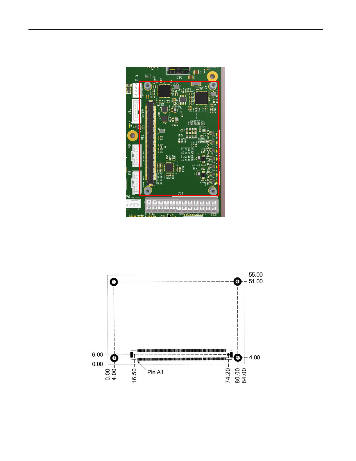
COM Express Type 10 CPU Site
P11, Single 220 Pin (A-B) COM Express Connector
This site supports the COM (Computer on Module) Express Type 10 Mini CPU Module form factor (84mm x 55
mm) CPU Modules with A Single 220 Pin (A-B) COM Express Connector.
NOTE:
The CPU Modules are typically low power, 12W or less. It is recommended the CPU module have a minimum of
4 PCI Express x1 Lanes: 0/1/2/3 configured to x4.

ACEX4041 COM Express Type 10 AcroPack Carrier Board
-
12
-
Connector Pin Assignments
Pin
Row A
Row B
1
GND
GND
2
NO CONNECT1
NO CONNECT1
3
NO CONNECT1
LPC_FRAME#
4
NO CONNECT1
LPC_AD0
5
NO CONNECT1
LPC_AD1
6
NO CONNECT1
LPC_AD2
7
NO CONNECT1
LPC_AD3
8
NO CONNECT1
NO CONNECT1
9
NO CONNECT1
NO CONNECT1
10
NO CONNECT1
LPC_CLK
11
GND
GND
12
NO CONNECT1
PWRBTN#
13
NO CONNECT1
SMB_CK
14
NO CONNECT1
SMB_DAT
15
SUS_S3#
SMB_ALERT#
16
SATA0_TX+
SATA1_TX+
17
SATA0_TX-
SATA1_TX-
18
SUS_S4#
NO CONNECT1
19
SATA0_RX+
SATA1_RX+
20
SATA0_RX-
SATA1_RX-
21
GND
GND
22
USB_SSRX0-
USB_SSTX0-
23
USB_SSRX0+
USB_SSTX0+
24
SUS_S5#
PWR_OK
25
USB_SSRX1-
USB_SSTX1-
26
USB_SSRX1+
USB_SSTX1+
27
BATLOW#
NO CONNECT1
28
SATA_ACT#
NO CONNECT1
29
AC/HDA_SYNC
NO CONNECT1
30
AC/HDA_RST#
AC/HDA_SDIN0
31
GND
GND
32
AC/HDA_BITCLK
NO CONNECT1
33
AC/HDA_SDOUT
I2C_CK

ACEX4041 COM Express Type 10 AcroPack Carrier Board
-
13
-
Pin
Row A
Row B
34
NO CONNECT1
12C_DAT
35
NO CONNECT1
NO CONNECT1
36
NO CONNECT1
NO CONNECT1
37
NO CONNECT1
NO CONNECT1
38
NO CONNECT1
NO CONNECT1
39
NO CONNECT1
NO CONNECT1
40
NO CONNECT1
NO CONNECT1
41
GND
GND
42
NO CONNECT1
NO CONNECT1
43
NO CONNECT1
NO CONNECT1
44
NO CONNECT1
USB_0_1_OC#
45
USB0-
USB1-
46
USB0+
USB1+
47
VCC_RTC
NO CONNECT1
48
NO CONNECT1
NO CONNECT1
49
NO CONNECT1
SYS_RESET#
50
NO CONNECT1
CB_RESET#
51
GND
GND
52
RSVD2
RSVD2
53
RSVD2
RSVD2
54
GPI0
GPO1
55
RSVD2
RSVD2
56
RSVD2
RSVD2
57
GND
GPO2
58
PCIE_TX3+
PCIE_RX3+
59
PCIE_TX3-
PCIE_RX3-
60
GND
GND
61
PCIE_TX2+
PCIE_RX2+
62
PCIE_TX2-
PCIE_RX2-
63
GPI1
GPO3
64
PCIE_TX1+
PCIE_RX1+
65
PCIE_TX1-
PCIE_RX1-
66
GND
WAKE0#
67
GPI2
NO CONNECT1

ACEX4041 COM Express Type 10 AcroPack Carrier Board
-
14
-
Pin
Row A
Row B
68
PCIE_TX0+
PCIE_RX0+
69
PCIE_TX0-
PCIE_RX0-
70
GND
GND
71
NO CONNECT1
DDIO_PAIR0+
72
NO CONNECT1
DDIO_PAIR0-
73
NO CONNECT1
DDIO_PAIR1+
74
NO CONNECT1
DDIO_PAIR1-
75
NO CONNECT1
DDIO_PAIR2+
76
NO CONNECT1
DDIO_PAIR2-
77
NO CONNECT1
NO CONNECT1
78
NO CONNECT1
NO CONNECT1
79
NO CONNECT1
NO CONNECT1
80
GND
GND
81
NO CONNECT1
DDIO_PAIR3+
82
NO CONNECT1
DDIO_PAIR3-
83
NO CONNECT1
NO CONNECT1
84
NO CONNECT1
VCC_5V_SBY
85
GPI3
VCC_5V_SBY
86
RSVD2
VCC_5V_SBY
87
NO CONNECT1
VCC_5V_SBY
88
PCIE_CLK_REF+
NO CONNECT1
89
PCIE_CLK_REF-
DD0_HPD
90
GND
GND
91
NO CONNECT1
NO CONNECT1
92
NO CONNECT1
NO CONNECT1
93
GPO0
NO CONNECT1
94
NO CONNECT1
NO CONNECT1
95
NO CONNECT1
DDIO_DDC_AUX_SEL
96
NO CONNECT1
NO CONNECT1
97
TYPE10#
(NO CONNECT)
NO CONNECT1
98
SER0_TX
DDIO_CTRLCLK_AUX+
99
SER0_RX
DDIO_CTRLCLK_AUX-
100
GND
GND
101
SER1_TX
FAN_PWMOUT

ACEX4041 COM Express Type 10 AcroPack Carrier Board
-
15
-
Pin
Row A
Row B
102
SER1_RX
FAN_TACHIN
103
NO CONNECT1
NO CONNECT1
104
VCC_12V
VCC_12V
105
VCC_12V
VCC_12V
106
VCC_12V
VCC_12V
107
VCC_12V
VCC_12V
108
VCC_12V
VCC_12V
109
VCC_12V
VCC_12V
110
GND
GND
For detailed signal descriptions, refer to the COM-Express Module Base Specification Rev. 2.1
Note 1: (NO CONNECT) The functionality of the signals on these pins as described in the COM Express Module
Base Specification Rev. 2.1 is not available on the ACEX4041.
Note 2: (RSVD) These signals are not connected.
ACEX4041 COM Express Type 10 AcroPack Carrier Board
-
16
-
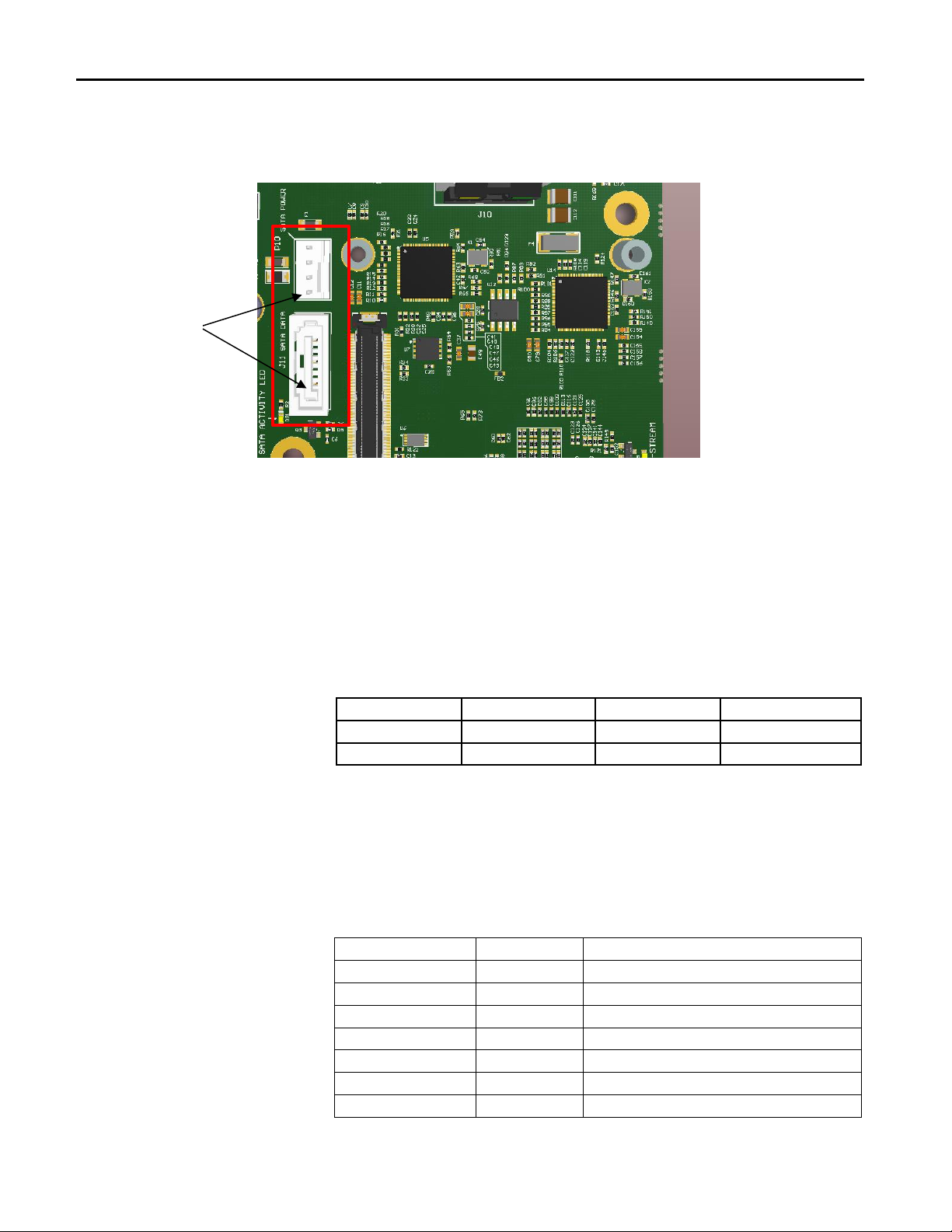
SATA Interface
P10, SATA Power connector
The SATA power connector is a 4-pin header. The SATA power connector is labeled P10 on the
carrier. There is one ground and two power signals 5V, and +12V available on this connector. All
power supplies are independently fused with a Resettable PTC fuse. At +12V the fuse is rated to
0.5A. The +5V is rated to 1.1A. A +3.3V supply is optionally available on Pin 3. Fuse F2 is currently
open on the carrier and must be installed to bring +3.3V power to pin 3 of this connector. This
connector is a Molex 470531000 header.
Connector Pin Assignments
Pin Number
Signal Name
Pin Number
Signal Name
1
GND
2
+12V
3
+3.3V (OPEN)
4
+5V
J11, SATA Data connector
The SATA Data connector is a 7-pin socket. There are three grounds and four active data lines in
two pairs. SATA Data is labeled J11 on the carrier. Supports SATA III devices, speeds up to 6Gb/s.
The connector is Molex 67800-8005 socket.
Connector Pin Assignments
Pin Number
Signal Name
Function
1
GND
Ground
2
SATA_TX_P
Transmit +
3
SATA_TX_N
Transmit -
4
GND
Ground
5
SATA_RX_N
Receive -
6
SATA_RX_P
Receive +
7
GND
Ground
Pin 1
ACEX4041 COM Express Type 10 AcroPack Carrier Board
-
17
-
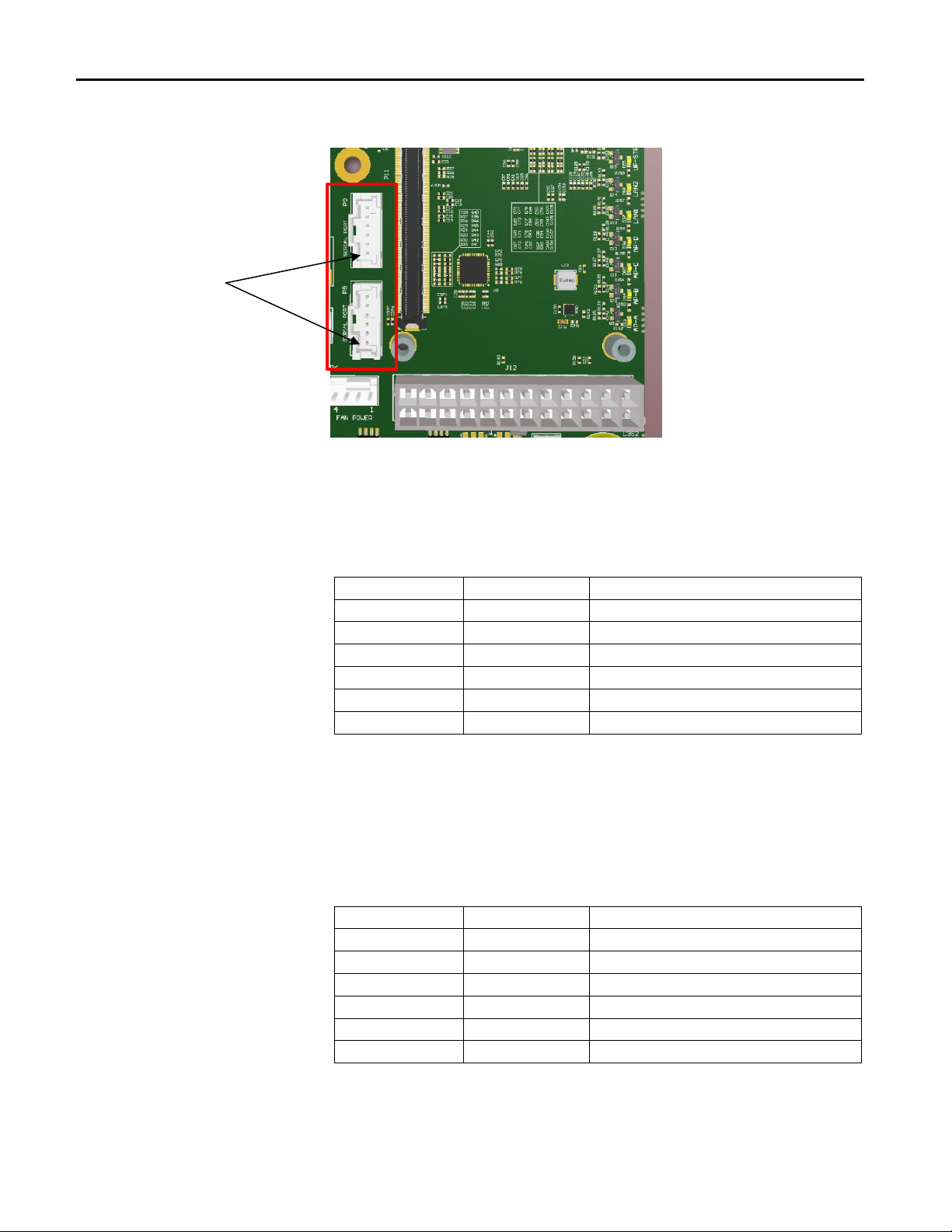
Serial Interface
P8, Serial Port connector
The Serial Port is General Purpose Serial Port capable of driving TTL signal levels. There are 2
grounds, 1 TX (Transmit) and 1 RX (Receive) signal. Serial Port is labeled P8 on the carrier. The
connector is a Molex 55932-0610 header.
Connector Pin Assignments
Pin Number
Signal Name
Function
1
NC
No connect
2
NC
No connect
3
RX
Receive
4
TX
Transmit
5
GND
Ground
6
GND
Ground
P9, Serial Port connector
The Serial Port is General Purpose Serial Port capable of driving TTL signal levels. There are 2
grounds, 1 TX (Transmit) and 1 RX (Receive) signal. Serial Port is labeled P9 on the carrier. The
connector is a Molex 55932-0610 header.
Connector Pin Assignments
Pin Number
Signal Name
Function
1
NC
No connect
2
NC
No connect
3
RX
Receive
4
TX
Transmit
5
GND
Ground
6
GND
Ground
Note: RS-485/422 serial communication is not supported.
Pin 1

ACEX4041 COM Express Type 10 AcroPack Carrier Board
-
18
-
Audio Interface
P13, Audio I/O connector
The ACEX4041 provides a Realtek HD Audio CODEC (ALC892) The Audio interface uses the Front left
and Right channels for output and Line In left and right for Input. There are 2 Line-In signals and 2
Line-out signals and 2 grounds. The Audio Port is labeled P13. The connector is a Molex 55932-0610
socket header.
Connector Pin Assignments
Pin Number
Signal Name
Function
1
Line Out Left
Front-L
2
Line Out Right
Front-R
3
GND
Ground
4
GND
Ground
5
Line in Left
Line1-L
6
Line in Right
Line1-R
Pin 1

ACEX4041 COM Express Type 10 AcroPack Carrier Board
-
19
-
CPU Fan Power Connector
P6, CPU Fan Power connector
The CPU Fan Power connector is a 4-pin conductor header. The CPU Fan Power connector is
labeled P6 on the carrier. The COM Express module drives both the CPU Fan tachometer control
(Pin 3) and the CPU Fan pulse width modulation control (Pin 4). This connector is a Molex
470531000 header.
Connector Pin Assignments
Pin Number
Signal Name
Pin Number
Signal Name
1
GND
2
+12V
3
Tachometer
4
Control

ACEX4041 COM Express Type 10 AcroPack Carrier Board
-
20
-
JTAG Programming/Debug Connector
P5, JTAG Programming/Debug
A JTAG programming/debug connector is provided for developing applications that use Acromag’s
FPGA AcroPack modules. This is a standard 14-pin Xilinx programming header for connecting a
Xilinx Platform USB II programming device (or equivalent). The pin assignment for P5 is shown
below. A bypass circuit is included that will detect a vacant AcroPack site and close a switch to
bypass the TDI and TDO signals. A CPLD on the carrier is included in the JTAG chain. The Xilinx
Vivado tools can detect the presence of the CPLD in the JTAG chain and skip it when accessing the
FPGAs on the AcroPack modules. The connector is a Molex 87832-1420
Connector Pin Assignments
Notes:
NC –no connect
TMS –JTAG Test Mode Select. This pin is the JTAG mode signal establishing
appropriate TAP state transitions for target ISP devices sharing the same data
stream.
TCK –JTAG Test Clock. This pin is the clock signal for JTAG operations and should be
connected to the TCK pin on all target ISP devices sharing the same data
stream.
TDO –JTAG Test Data Out. This pin is the serial data stream received from the TDO
pin on the last device in a JTAG chain.
TDI –JTAG Test Data In. This pin outputs the serial data stream transmitted to the TDI
pin on the first device in a JTAG chain.
+3.3V –The target reference voltage VREF is 3.3 Volts
GND –Signal Return
Pin Number
Signal Name
Pin Number
Signal Name
1
NC1
2
+3.3V
3
GND
4
TMS
5
GND
6
TCK
7
GND
8
TDO
9
GND
10
TDI
11
GND
12
NC1
13
NC1
14
NC1
Pin 1
Pin 2
Table of contents
Other Acromag Carrier Board manuals

Acromag
Acromag AVME9675 Series User manual

Acromag
Acromag XMCAP2022 User manual

Acromag
Acromag VPX4812A User manual

Acromag
Acromag ACPC4610E/CC User manual

Acromag
Acromag VPX4812 User manual

Acromag
Acromag AVME9675A Series User manual

Acromag
Acromag APC8620 Series User manual

Acromag
Acromag AVME9630 Series User manual


