Acromag XMCAP2022 User manual

XMCAP2022 XMC AcroPack Carrier Boards
For ARCX Applications
USER’S MANUAL
ACROMAG INCORPORATED
30765 South Wixom Road
Wixom, MI 48393-2417 U.S.A.
Tel: (248) 295-0310
Copyright 2019, Acromag, Inc., Printed in the USA.
Data and specifications are subject to change without notice.
8501131C

AcroPack Series XMCAP2022 XMC Carrier Board
-
2
-
Table of Contents
1. GENERAL INFORMATION ...................................................................................................................... 4
Intended Audience................................................................................................................................ 4
Preface .................................................................................................................................................. 4
Trademark, Trade Name and Copyright Information ........................................................................... 4
Environmental Protection Statement................................................................................................... 4
XMCAP2022 OVERVIEW........................................................................................................................ 4
Ordering Information ......................................................................................................................... 5
KEY XMCAP2022 FEATURES.................................................................................................................. 5
SIGNAL INTERFACE PRODUCTS............................................................................................................. 5
JTAG Adapter Cable............................................................................................................................ 5
2. PREPARATION FOR USE ........................................................................................................................ 6
UNPACKING AND INSPECTION.............................................................................................................. 6
BOARD CONFIGURATION...................................................................................................................... 7
CARRIER ADDRESS ASSIGNMENT.......................................................................................................... 8
ACROPACK HEATSINKING ..................................................................................................................... 8
ACROPACK MODULE INSTALLATION..................................................................................................... 9
FIELD GROUNDING CONSIDERATIONS................................................................................................ 10
CONNECTORS...................................................................................................................................... 10
Rear Field I/O Connectors ................................................................................................................ 10
AcroPack Field I/O Connectors......................................................................................................... 11
ARCX 4000 Series Cross Reference................................................................................................... 17
Mini-PCIe Connectors....................................................................................................................... 21
XMC/PCIe Bus Connections.............................................................................................................. 22
JTAG Programming/Debug Connector............................................................................................. 22
3. PROGRAMMING INFORMATION......................................................................................................... 24
4. THEORY OF OPERATION...................................................................................................................... 24
PCIe SWITCH ....................................................................................................................................... 24
DC/DC CONVERTERS ........................................................................................................................... 24
SLOT ADDRESSING .............................................................................................................................. 24
JTAG .................................................................................................................................................... 25
POWER SUPPLY FET SWITCHES........................................................................................................... 25
5. SERVICE AND REPAIR .......................................................................................................................... 26
PRELIMINARY SERVICE PROCEDURE................................................................................................... 26
WHERE TO GET HELP .......................................................................................................................... 26
6. SPECIFICATIONS .................................................................................................................................. 27
PHYSICAL............................................................................................................................................. 27
Physical Configuration (conforms to VITA 42 air-cooled XMC Specification) .................................. 27

AcroPack Series XMCAP2022 XMC Carrier Board
-
3
-
Connectors ....................................................................................................................................... 27
POWER................................................................................................................................................ 27
PCIe BUS COMPLIANCE....................................................................................................................... 28
ENVIRONMENTAL ............................................................................................................................... 28
EMC Compliance .............................................................................................................................. 28
Vibration and Shock Standard.......................................................................................................... 28
Reliability Prediction ........................................................................................................................ 29
7. APPENDIX A......................................................................................................................................... 30
Heatsink Installation ........................................................................................................................... 30
8. APPENDIX B......................................................................................................................................... 31
XMCAP202x Module Installation ........................................................................................................ 31
9. CERTIFICATE OF VOLATILITY ............................................................................................................... 33
10. REVISION HISTORY.............................................................................................................................. 34

AcroPack Series XMCAP2022 XMC Carrier Board
-
4
-
1. GENERAL INFORMATION
Intended Audience
This users’ manual was written for technically qualified personnel who will be
working with I/O devices using the AcroPack module.
Preface
The information contained in this manual is subject to change without notice,
and Acromag, Inc. (Acromag) does not guarantee its accuracy. Acromag
makes no warranty of any kind with regard to this material, including, but not
limited to, the implied warranties of merchantability and fitness for a
particular purpose. Further, Acromag assumes no responsibility for any errors
that may appear in this manual and makes no commitment to update, or keep
current, the information contained in this manual. No part of this manual may
be copied or reproduced in any form, without the prior written consent of
Acromag.
Trademark, Trade Name and Copyright Information
© 2018 by Acromag Incorporated.
All rights reserved. Acromag and Xembedded are registered trademarks of
Acromag Incorporated. All other trademarks, registered trademarks, trade
names, and service marks are the property of their respective owners.
Environmental Protection Statement
This product has been manufactured to satisfy environmental protection
requirements where possible. Many components used (structural parts,
circuit boards, connectors, etc.) are capable of being recycled. Final
disposition of this product after its service life must be conducted in
accordance with applicable country, state, or local laws or regulations.
XMCAP2022 OVERVIEW
The XMCAP2022 is a carrier for mini-PCIe or AcroPack mezzanine modules in
an XMC form factor. This carrier board provides a modular approach to
system assembly, since each carrier can be populated with any combination
of analog input/output, digital input/output, communication, etc. AcroPack
modules. Thus, the user can create a board which is customized to the
application. This saves money and space - a single carrier board populated
with AcroPack modules may replace several dedicated function XMC modules.

AcroPack Series XMCAP2022 XMC Carrier Board
-
5
-
Ordering Information
The XMCAP2022-LF was designed for use in the ARCX4000 series. It is the
same as the XMCAP2021-LF but with different routing to the Rear I/O
connectors P14 and P16.
Model
I/O Type
XMCAP2022-LF
Rear (P14 & P16) For
ARCX4000
applications
KEY XMCAP2022 FEATURES
Interface for AcroPack modules –The XMCAP2022 provides an electrical and
mechanical interface for up to two industry standard mini-PCIe or AcroPack
modules. AcroPack modules are available from Acromag. Mini-PCIe cards are
available from other vendors in a wide variety of input/output configurations
to meet the needs of varied applications.
PCI Express Version 2.1 Compliant Carrier: - Includes a PCIe switch to allow
two PCIe devices (AcroPack or mini-PCIe) to share a single XMC slot on the
XMC carrier.
Board Identification –A unique carrier and site number can be set for each
AcroPack site automatically by geographical address bits or by DIP switch. This
feature provides the capability to distinguish a particular AcroPack module
from others when multiple instances of the same module are used in a
system.
JTAG Programming Header –JTAG programming is supported both through
the XMC P15 connector, as well as through a Molex 78171-5006 6-pin micro
connector (J3). This connection is provided for programming and debugging
the FPGA on some AcroPack modules. The JTAG ports of the two AcroPack
modules are daisy-chained.
SIGNAL INTERFACE PRODUCTS
This AcroPack carrier board will mate directly to most industry standard mini-
PCIe and AcroPack modules. Acromag provides the following interface
products (all connections to field signals are made through the carrier board
which passes them to the individual AcroPack modules):
JTAG Adapter Cable
Model 5028-564 JTAG Adapter Cable connects between J3 and a Xilinx USB
programmer. This cable is only required if JTAG is not available on the XMC
carrier through the P15 XMC connector.

AcroPack Series XMCAP2022 XMC Carrier Board
-
6
-
2. PREPARATION FOR USE
IMPORTANT PERSONAL AND PRODUCT SAFETY CONSIDERATIONS
It is very important for the user to consider the possible safety implications of
power, wiring, component, sensor, or software failures in designing any type
of control or monitoring system. This is especially important where personal
injury or the loss of economic property or human life is possible. It is
important that the user employ satisfactory overall system design. It is
understood and agreed by the Buyer and Acromag that this is the Buyer's
responsibility.
WARNING: This board utilizes static sensitive components and should only
be handled at a static-safe workstation. This product is an electrostatic
sensitive device and is packaged accordingly. Do not open or handle this
product except at an electrostatic-free workstation. Additionally, do not ship
or store this product near strong electrostatic, electromagnetic, magnetic, or
radioactive fields unless the device is contained within its original
manufacturer’s packaging. Be aware that failure to comply with these
guidelines will void the Acromag Limited Warranty.
UNPACKING AND INSPECTION
Upon receipt of this product, inspect the shipping carton for evidence of
mishandling during transit. If the shipping carton is badly damaged or water
stained, request that the carrier's agent be present when the carton is
opened. If the carrier's agent is absent when the carton is opened and the
contents of the carton are damaged, keep the carton and packing material for
the agent's inspection.
For repairs to a product damaged in shipment, refer to the Acromag Service
Policy to obtain return instructions. It is suggested that salvageable shipping
cartons and packing material be saved for future use in the event the product
must be shipped.
This board is physically protected with packing material and electrically
protected with an anti-static bag during shipment. It is recommended that the
board be visually inspected for evidence of mishandling prior to applying
power.
The board utilizes static sensitive components and should only be handled at
a static-safe workstation.

AcroPack Series XMCAP2022 XMC Carrier Board
-
7
-
BOARD CONFIGURATION
Power should be removed from the board when changing switch
configurations or when installing AcroPack modules, cables and field wiring.
Figure 1 XMCAP2022 Primary Side
Refer to the specifications for loading and power requirements. Be sure that
the system power supplies are able to accommodate the power requirements
of the carrier board, plus the installed AcroPack modules within the voltage
tolerances specified.
IMPORTANT: Adequate thermos conduction must be provided to prevent a temperature rise above the
maximum operating temperature.
The lack of thermo conduction from the XMC carrier could be a cause for
some concern. Adequate thermo conduction must be provided to prevent a
temperature rise above the maximum operating temperature and to prolong
the life of the electronics.

AcroPack Series XMCAP2022 XMC Carrier Board
-
8
-
CARRIER ADDRESS ASSIGNMENT
Following are the instructions for setting the slot address of the carrier. By
assigning a unique address to each carrier, system software can distinguish
this carrier from other similarly configured carriers installed in a system.
Address bits A0, A1, and A2 are connected to the corresponding Geographical
Addressing (GA) bits of the XMC P15 connector. This should automatically
assign a unique address to the XMCAP2022 board.
If the GA bits are not supplied by the XMC carrier onto which the XMCAP2022
board is installed, SW1 may be used to select address bits A3 and A4. Figure 1
shows the location of switch SW1. Set the switch state as shown in Table 1
below to assign a unique slot address to this carrier.
Table 1 Switch SW1 assignments
SW1 Position
Address Bit
Value
1-2
A3
1
2-3
0
4-5
A4
1
5-6
0
ACROPACK HEATSINKING
Most applications require the use of a nonstandard heatsink. Consult the
factory for each application. See Appendix A for the installation of the
heatsink.
Available XMCAP202x heatsinks for use in ARCX box applications:
•AP-CC-02: Dual generic AcroPack (left rail or single wide ARCX)
•AP-CC-03: AP57x with generic AP (left rail or single wide ARCX)
•AP-CC-05: Dual generic AP (right rail)
Where “generic” AcroPack refers to:
•AP220-16E-LF
•AP225-16E-LF
•AP226-8E-LF
•AP231-16E-LF
•AP235-16E-LF
•AP236-8E-LF
•AP323E-LF
•AP341E-LF
•AP342E-LF
•AP408E-LF

AcroPack Series XMCAP2022 XMC Carrier Board
-
9
-
•AP418E-LF
•AP445E-LF
•AP471E-LF
•AP482/3/4E-LF
•AP500E-LF
•AP512E-LF
•AP520-64E-LF
•AP521-64E-LF
•AP522E-LF
•APA7-201/2/3/4E-LF
•APA7-501/2/3/4E-LF
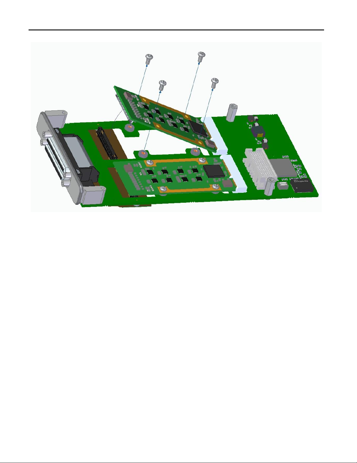
ACROPACK MODULE INSTALLATION
Power should be removed from the carrier board when installing AcroPack
modules, cables, termination panels, and field wiring. Refer to Figure 4 while
reading this section. Place the XMCAP2022 flat on an anti-static surface for
support. To install, first insert the edge of the AcroPack module into the
carrier connector at an angle similar to that shown in the figure. Next, using a
rocking motion while gently applying force to keep the edge of the board
against the back of the carrier connector, position the module such that the
field I/O connector is just above the mating connector. Verify that the two
connectors are properly aligned. Once alignment is achieved, you can fully
seat the connector. It will snap into place. Install four M2.5 screws as shown.
Refer to Appendix B for the installation of the XMC card into the ARCX XMC
site.
Note: The AP441E-LF is not recommended for use with the XMC AcroPack
carrier.
WARNING: When installing a commercial mini-PCIe module onto the
XMCAP2022 board be sure that pin 45 on the module's mini-PCIe connector
is not grounded or damage to the module may result.
AcroPack Series XMCAP2022 XMC Carrier Board
-
10
-
Figure 4 AcroPack Module Installation
FIELD GROUNDING CONSIDERATIONS
Care should be taken in designing installations without isolation to avoid
ground loops and noise pickup. This is particularly important for analog I/O
applications when a high level of accuracy/resolution is needed (12-bits or
more). Contact your Acromag representative for information on our many
isolated signal conditioning products that could be used to interface to the
AcroPack input/output modules.
CONNECTORS
The XMCAP2022 carrier uses two AcroPack module field I/O connectors, two
mini-PCIe connectors, two field I/O connectors (rear P14 & P16 connectors for
XMCAP2022) and one XMC bus interface connector. These are discussed in
the following sections.
Rear Field I/O Connectors
Field I/O connections on the XMCAP2022 model are made via the P14 and
P16 connectors. The Field I/O connections from the AcroPack module in Site A
are available through the XMC P16 and PMC P14 connector. The Field I/O
connections from the AcroPack module in Site B are available through the
PMC P14 connector.

AcroPack Series XMCAP2022 XMC Carrier Board
-
11
-
See Table 2.A below for pin assignments for Slot A and Table 2.B for pin
assignments for Slot B.
AcroPack Field I/O Connectors
The field side connector of AcroPack modules mate to Samtec
SS5-50-3.00-L-D-K-TR socket connectors on the carrier board.
This provides excellent connection integrity due to the gold plating in the
mating area. M2.5 screws and spacers provide additional stability for harsh
environments.
The functions of each of the Field I/O signals are defined by the installed
AcroPack model.
Table 2.A Field I/O Pin Assignments AcroPack A
XMCAP2022
Rear I/O
Connection
(Site A - P16)
XMCAP2022
Rear I/O
Connection
(Site A - P14)
Carrier
P1, P2
Samtec
SS5-50-3.00-L-D-K-TR
Module
Pin
Number
Field A I/O Signal
C3
2
2
Field A I/O 1
C2
1
1
Field A I/O 2
4
4
Reserved/isolation
3
3
Reserved/isolation
C5
6
6
Field A I/O 3
C4
5
5
Field A I/O 4
8
8
Reserved/isolation
7
7
Reserved/isolation
F5
10
10
Field A I/O 5
F4
9
9
Field A I/O 6
12
12
Reserved/isolation
11
11
Reserved/isolation
F7
14
14
Field A I/O 7
F6
13
13
Field A I/O 8
16
16
Reserved/isolation
15
15
Reserved/isolation
F19
18
18
Field A I/O 9
F18
17
17
Field A I/O 10
20
20
Reserved/isolation
19
19
Reserved/isolation
C19
22
22
Field A I/O 11
C18
21
21
Field A I/O 12
24
24
Reserved/isolation
23
23
Reserved/isolation

AcroPack Series XMCAP2022 XMC Carrier Board
-
12
-
XMCAP2022
Rear I/O
Connection
(Site A - P16)
XMCAP2022
Rear I/O
Connection
(Site A - P14)
Carrier
P1, P2
Samtec
SS5-50-3.00-L-D-K-TR
Module
Pin
Number
Field A I/O Signal
C7
26
26
Field A I/O 13
C6
25
25
Field A I/O 14
28
28
Reserved/isolation
27
27
Reserved/isolation
F1
30
30
Field A I/O 15
C1
29
29
Field A I/O 16
32
32
Reserved/isolation
31
31
Reserved/isolation
C9
34
34
Field A I/O 17
C8
33
33
Field A I/O 18
36
36
Reserved/isolation
35
35
Reserved/isolation
F3
38
38
Field A I/O 19
F2
37
37
Field A I/O 20
40
40
Reserved/isolation
39
39
Reserved/isolation
F11
42
42
Field A I/O 21
F10
41
41
Field A I/O 22
44
44
Reserved/isolation
43
43
Reserved/isolation
F8
46
46
Field A I/O 23
F9
45
45
Field A I/O 24
48
48
Reserved/isolation
47
47
Reserved/isolation
62
50
50
Field A I/O 25
64
49
49
Field A I/O 26
52
52
Reserved/isolation
51
51
Reserved/isolation
56
54
54
Field A I/O 27
54
53
53
Field A I/O 28
56
56
Reserved/isolation
55
55
Reserved/isolation
F13
58
58
Field A I/O 29
F12
57
57
Field A I/O 30
60
60
Reserved/isolation

AcroPack Series XMCAP2022 XMC Carrier Board
-
13
-
XMCAP2022
Rear I/O
Connection
(Site A - P16)
XMCAP2022
Rear I/O
Connection
(Site A - P14)
Carrier
P1, P2
Samtec
SS5-50-3.00-L-D-K-TR
Module
Pin
Number
Field A I/O Signal
59
59
Reserved/isolation
C10
62
62
Field A I/O 31
C11
61
61
Field A I/O 32
64
64
Reserved/isolation
63
63
Reserved/isolation
58
66
66
Field A I/O 33
60
65
65
Field A I/O 34
68
68
Reserved/isolation
67
67
Reserved/isolation
C15
70
70
Field A I/O 35
C14
69
69
Field A I/O 36
72
72
Reserved/isolation
71
71
Reserved/isolation
F15
74
74
Field A I/O 37
F14
73
73
Field A I/O 38
76
76
Reserved/isolation
75
75
Reserved/isolation
59
78
78
Field A I/O 39
57
77
77
Field A I/O 40
80
80
Reserved/isolation
79
79
Reserved/isolation
50
82
82
Field A I/O 41
52
81
81
Field A I/O 42
84
84
Reserved/isolation
83
83
Reserved/isolation
C13
86
86
Field A I/O 43
C12
85
85
Field A I/O 44
88
88
Reserved/isolation
87
87
Reserved/isolation
F17
90
90
Field A I/O 45
F16
89
89
Field A I/O 46
92
92
Reserved/isolation
91
91
Reserved/isolation
63
94
94
Field A I/O 47
61
93
93
Field A I/O 48

AcroPack Series XMCAP2022 XMC Carrier Board
-
14
-
XMCAP2022
Rear I/O
Connection
(Site A - P16)
XMCAP2022
Rear I/O
Connection
(Site A - P14)
Carrier
P1, P2
Samtec
SS5-50-3.00-L-D-K-TR
Module
Pin
Number
Field A I/O Signal
96
96
Reserved/isolation
95
95
Reserved/isolation
55
98
98
Field A I/O 49
53
97
97
Field A I/O 50
100
100
Reserved/isolation
99
99
Reserved/isolation
Table 2.B Field I/O Pin Assignments AcroPack B
XMCAP2022
Rear I/O
Connection
(Site B - P14)
Carrier
P1, P2
Samtec
SS5-50-3.00-L-D-K-
TR
Module
Pin
Number
Field B I/O Signal
1
2
2
Field B I/O 1
3
1
1
Field B I/O 2
4
4
Reserved/isolation
3
3
Reserved/isolation
2
6
6
Field B I/O 3
4
5
5
Field B I/O 4
8
8
Reserved/isolation
7
7
Reserved/isolation
5
10
10
Field B I/O 5
7
9
9
Field B I/O 6
12
12
Reserved/isolation
11
11
Reserved/isolation
6
14
14
Field B I/O 7
8
13
13
Field B I/O 8
16
16
Reserved/isolation
15
15
Reserved/isolation
9
18
18
Field B I/O 9
11
17
17
Field B I/O 10
20
20
Reserved/isolation
19
19
Reserved/isolation
10
22
22
Field B I/O 11
12
21
21
Field B I/O 12
24
24
Reserved/isolation

AcroPack Series XMCAP2022 XMC Carrier Board
-
15
-
XMCAP2022
Rear I/O
Connection
(Site B - P14)
Carrier
P1, P2
Samtec
SS5-50-3.00-L-D-K-
TR
Module
Pin
Number
Field B I/O Signal
23
23
Reserved/isolation
13
26
26
Field B I/O 13
15
25
25
Field B I/O 14
28
28
Reserved/isolation
27
27
Reserved/isolation
14
30
30
Field B I/O 15
16
29
29
Field B I/O 16
32
32
Reserved/isolation
31
31
Reserved/isolation
17
34
34
Field B I/O 17
19
33
33
Field B I/O 18
36
36
Reserved/isolation
35
35
Reserved/isolation
18
38
38
Field B I/O 19
20
37
37
Field B I/O 20
40
40
Reserved/isolation
39
39
Reserved/isolation
21
42
42
Field B I/O 21
23
41
41
Field B I/O 22
44
44
Reserved/isolation
43
43
Reserved/isolation
22
46
46
Field B I/O 23
24
45
45
Field B I/O 24
48
48
Reserved/isolation
47
47
Reserved/isolation
25
50
50
Field B I/O 25
27
49
49
Field B I/O 26
52
52
Reserved/isolation
51
51
Reserved/isolation
26
54
54
Field B I/O 27
28
53
53
Field B I/O 28
56
56
Reserved/isolation
55
55
Reserved/isolation
29
58
58
Field B I/O 29
31
57
57
Field B I/O 30

AcroPack Series XMCAP2022 XMC Carrier Board
-
16
-
XMCAP2022
Rear I/O
Connection
(Site B - P14)
Carrier
P1, P2
Samtec
SS5-50-3.00-L-D-K-
TR
Module
Pin
Number
Field B I/O Signal
60
60
Reserved/isolation
59
59
Reserved/isolation
30
62
62
Field B I/O 31
32
61
61
Field B I/O 32
64
64
Reserved/isolation
63
63
Reserved/isolation
33
66
66
Field B I/O 33
35
65
65
Field B I/O 34
68
68
Reserved/isolation
67
67
Reserved/isolation
34
70
70
Field B I/O 35
36
69
69
Field B I/O 36
72
72
Reserved/isolation
71
71
Reserved/isolation
37
74
74
Field B I/O 37
39
73
73
Field B I/O 38
76
76
Reserved/isolation
75
75
Reserved/isolation
38
78
78
Field B I/O 39
40
77
77
Field B I/O 40
80
80
Reserved/isolation
79
79
Reserved/isolation
41
82
82
Field B I/O 41
43
81
81
Field B I/O 42
84
84
Reserved/isolation
83
83
Reserved/isolation
42
86
86
Field B I/O 43
44
85
85
Field B I/O 44
88
88
Reserved/isolation
87
87
Reserved/isolation
45
90
90
Field B I/O 45
47
89
89
Field B I/O 46
92
92
Reserved/isolation
91
91
Reserved/isolation
46
94
94
Field B I/O 47

AcroPack Series XMCAP2022 XMC Carrier Board
-
17
-
XMCAP2022
Rear I/O
Connection
(Site B - P14)
Carrier
P1, P2
Samtec
SS5-50-3.00-L-D-K-
TR
Module
Pin
Number
Field B I/O Signal
48
93
93
Field B I/O 48
96
96
Reserved/isolation
95
95
Reserved/isolation
49
98
98
Field B I/O 49
51
97
97
Field B I/O 50
100
100
Reserved/isolation
99
99
Reserved/isolation
ARCX 4000 Series Cross Reference
The Table below is a cross-reference for the ARCX box connections.
Pin 38999
J3/J5*
Pin PMC
J14/J24*
Pin XMC
J16/J26*
XMCAP2022 Signal
Name
1
1
Field B I/O 1
2
3
Field B I/O 2
3
2
Field B I/O 3
4
4
Field B I/O 4
5
5
Field B I/O 5
6
7
Field B I/O 6
7
6
Field B I/O 7
8
8
Field B I/O 8
9
N/A
#N/A
10
9
Field B I/O 9
11
11
Field B I/O 10
12
N/A
#N/A
13
10
Field B I/O 11
14
12
Field B I/O 12
15
N/A
#N/A
16
13
Field B I/O 13
17
15
Field B I/O 14
18
14
Field B I/O 15
19
16
Field B I/O 16
20
17
Field B I/O 17
21
19
Field B I/O 18
22
18
Field B I/O 19
23
20
Field B I/O 20
24
21
Field B I/O 21

AcroPack Series XMCAP2022 XMC Carrier Board
-
18
-
Pin 38999
J3/J5*
Pin PMC
J14/J24*
Pin XMC
J16/J26*
XMCAP2022 Signal
Name
25
23
Field B I/O 22
26
N/A
#N/A
27
22
Field B I/O 23
28
24
Field B I/O 24
29
25
Field B I/O 25
30
27
Field B I/O 26
31
N/A
#N/A
32
26
Field B I/O 27
33
28
Field B I/O 28
34
29
Field B I/O 29
35
31
Field B I/O 30
36
N/A
#N/A
37
30
Field B I/O 31
38
32
Field B I/O 32
39
N/A
#N/A
40
N/A
#N/A
41
33
Field B I/O 33
42
35
Field B I/O 34
43
34
Field B I/O 35
44
36
Field B I/O 36
45
N/A
#N/A
46
N/A
#N/A
47
37
Field B I/O 37
48
39
Field B I/O 38
49
N/A
#N/A
50
38
Field B I/O 39
51
40
Field B I/O 40
52
41
Field B I/O 41
53
43
Field B I/O 42
54
N/A
#N/A
55
42
Field B I/O 43
56
44
Field B I/O 44
57
45
Field B I/O 45
58
47
Field B I/O 46
59
N/A
#N/A
60
46
Field B I/O 47
61
48
Field B I/O 48
62
49
Field B I/O 49

AcroPack Series XMCAP2022 XMC Carrier Board
-
19
-
Pin 38999
J3/J5*
Pin PMC
J14/J24*
Pin XMC
J16/J26*
XMCAP2022 Signal
Name
63
51
Field B I/O 50
64
N/A
#N/A
65
50
Field A I/O 41
66
52
Field A I/O 42
67
53
Field A I/O 50
68
55
Field A I/O 49
69
N/A
#N/A
70
54
Field A I/O 28
71
56
Field A I/O 27
72
57
Field A I/O 40
73
59
Field A I/O 39
74
N/A
#N/A
75
58
Field A I/O 33
76
60
Field A I/O 34
77
N/A
#N/A
78
61
Field A I/O 48
79
63
Field A I/O 47
80
N/A
#N/A
81
62
Field A I/O 25
82
64
Field A I/O 26
83
N/A
#N/A
84
C19
Field A I/O 11
85
C18
Field A I/O 12
86
F19
Field A I/O 9
87
F18
Field A I/O 10
88
C17
#N/A
89
C16
#N/A
90
F17
Field A I/O 45
91
F16
Field A I/O 46
92
C15
Field A I/O 35
93
C14
Field A I/O 36
94
N/A
#N/A
95
F15
Field A I/O 37
96
F14
Field A I/O 38
97
N/A
#N/A
98
C13
Field A I/O 43
99
C12
Field A I/O 44
100
N/A
#N/A

AcroPack Series XMCAP2022 XMC Carrier Board
-
20
-
Pin 38999
J3/J5*
Pin PMC
J14/J24*
Pin XMC
J16/J26*
XMCAP2022 Signal
Name
101
F13
Field A I/O 29
102
F12
Field A I/O 30
103
C11
Field A I/O 32
104
C10
Field A I/O 31
105
N/A
#N/A
106
F11
Field A I/O 21
107
F10
Field A I/O 22
108
C9
Field A I/O 17
109
C8
Field A I/O 18
110
N/A
#N/A
111
F9
Field A I/O 24
112
F8
Field A I/O 23
113
N/A
#N/A
114
C7
Field A I/O 13
115
C6
Field A I/O 14
116
N/A
#N/A
117
F7
Field A I/O 7
118
F6
Field A I/O 8
119
N/A
#N/A
120
C5
Field A I/O 3
121
C4
Field A I/O 4
122
N/A
#N/A
123
F5
Field A I/O 5
124
F4
Field A I/O 6
125
C3
Field A I/O 1
126
C2
Field A I/O 2
127
F3
Field A I/O 19
128
F2
Field A I/O 20
129
F1
Field A I/O 15
130
C1
Field A I/O 16
*J5, J24 and J26 are only available on ARCX-4120 double-wide enclosures.
Table of contents
Other Acromag Carrier Board manuals

Acromag
Acromag AVME9675 Series User manual

Acromag
Acromag AVME9630 Series User manual

Acromag
Acromag ACPC4610E/CC User manual

Acromag
Acromag VPX4812 User manual

Acromag
Acromag ACEX4041 User manual

Acromag
Acromag VPX4812A User manual

Acromag
Acromag AVME9675A Series User manual

Acromag
Acromag APC8620 Series User manual


