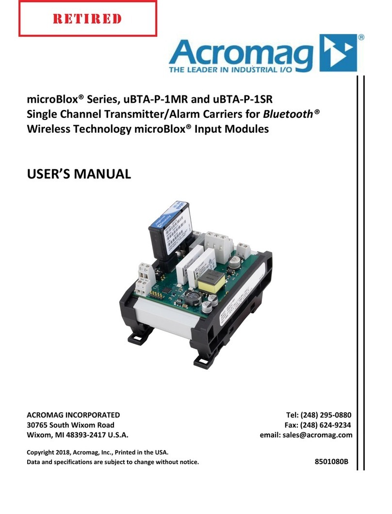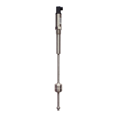
Model ST133-16x0 Two-Wire T/C Transmitter w/USB
___________________________________________________________________
______________________________________________________________________________________
Acromag, Inc. Tel:248-295-0880 Fax:248-624-9234 Email:sales@acromag.com http://www.acromag.com
12
POSSIBLE CAUSE POSSIBLE FI
Output shifts of
-range when
ou connect USB…
Indicative of a ground fault
between earth ground at the
PC and earth ground applied
at the input sensor, which
causes the 1.25V input bias
to connect to input
round.
Only connect to the unit via isolated USB
if your input sensor is grounded. You
can connect without USB isolation if the
input signal is not already grounded.
Output goes to Over
Range
24mA
or Under-Range Limit
3.5mA
…
This indicates that either the
input signal is out of range, or
a sensor lead has broken and
caused lead break detection
to send the output to its
upscale or downscale detent.
It can also occur due to
contention between earth
ground at the PC USB port
and the input sensor.
Check the input signal with respect to
range and reduce or increase as
required to drive the output current within
its linear operating range. A fully
upscale or down-scale signal is normally
driven by a sensor fault, such as an open
sensor or broken sensor lead, and this
behavior follows the break control
setting. Also check the wiring of your
input sensor. If you are not isolating
USB, check for a ground loop between a
grounded T/C and earth ground of the
PC USB port.
Unit fails to operate or exhibits an output shift…
Is input grounded at terminal
1 and at the sensor?
Is USB isolation not being
used with a grounded
sensor?
Isolated models are intended for use with
ungrounded or grounded sensors, but
you can only connect to grounded
sensors if the USB signals are isolated.
Only connect earth ground at terminal 1
if your input is ungrounded. The input is
normally biased 1.25V off input ground to
allow negative signals, and a grounded
probe could inadvertently connect this
bias to earth ground with a non-isolated
USB connection to a PC, or with earth
round alread
connected at terminal 1.
Unit drives a low current, but fails to drive current at/near/above 20mA…
Loop supply voltage is too
low to support a full-scale or
over-range current level in the
loop load.
Check power voltage level. Make sure it
is at least 12V plus 0.020*Rload. If
transmission distance is long, then it
must have additional voltage to support
the IR drop in the wire. Ideally, the
voltage should have ample overhead to
drive the load at the maximum upscale
output current of 24m
.
Output holds last value when I connect USB…
Unit is awaiting initialization
via its configuration software
used to set it up and
configure it.
Boot the configuration software to regain
operation. The USB port is intended for
setup and configuration of the module
and it should not be left connected to
USB without also bootin
the software.
Cannot Calibrate Input Channel…
Is input wired properly? Check that input is wired to input
terminals 2 & 3 usin
correct polarit
.
TROUBLE-SHOOTING
Diagnostics Table
Service & Repair Assistance
This unit contains solid-state
components and requires no
maintenance, except for
periodic cleaning and
transmitter configuration
parameter (zero and full-scale)
verification. The potted
Surface Mounted Technology
(SMT) board contained within
this enclosure is nearly
impossible to repair, except for
firmware. It is highly
recommended that a non-
functioning transmitter be
returned to Acromag for repair,
replacement, or re-
programming. Acromag has
automated test equipment that
thoroughly checks and
calibrates the performance of
each transmitter, and restores
its firmware. Please refer to
Acromag’s Service Policy and
Warranty Bulletins on our web
site, or contact Acromag for
complete details on how to
obtain repair or replacement.


