After you connect USB and “Open” communication with a unit, the
Status field indicates “Device opened successfully” as shown in first
screen at left.
At this point, you can click the “I/O Config/Test” tab to begin
configuring the unit, or to optionally test its operation.
When you click the “I/O Config/Test” tab, the software retrieves the
unit’s current configuration and displays it within the I/O Config/Test
page similar to the second screen shown at left. If you make changes
to this Configuration Screen, but do not write them to the unit, you can
retrieve the module’s current configuration by clicking the [Get I/O
Config] button at the top of this screen.
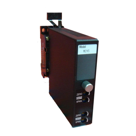
This model has two input channels, one for current, and one for
voltage. DC current input is wired to TB1 (the upper terminal block),
while DC voltage input is wired to TB2 (the lower terminal block). Only
one input may drive the output current loop at one time and this is
determined by your input range selection.
Select the Input Range…
You can select DC Current ranges of ±20mA, 0-20mA, 4-20mA, 0-
11.17mA, or ±1mA, and these signals must be wired to TB1. You can
also select DC Voltage ranges of ±0.5V or 0-500mV, and these signals
are wired to TB2.
Note that the any input range you pick can be rescaled to the output,
allowing you to use only a portion of the selected input range to drive
the 4-20mA output current loop, if desired. However, resolution will
decrease proportionally as you rescale the input smaller than the
nominal input range. If you reduce the input range too far, this will
reduce the signal resolution, magnify potential error, and degrades the
signal-to-noise ratio of the input channel.
Select the Input Filtering…
You may select the level of digital filtering to apply to the input channel
as Low, Medium, or High. The respective I/O response times are
indicated in parenthesis next to your filter selection. Note that higher
filter levels result in lower average noise, but with a slower I/O
response time.
Note that if you make any changes to this screen, which represents the
current configuration of the connected module, the only way to
preserve your changes is to either write it to the device by clicking
[Send I/O Config] after completing your changes, or by saving it to a
file by clicking “File” in the upper left-hand corner of the screen.


